

SMA SB3.0-1SP-US-40,SB3.8-1SP-US-40,SB7.7-1SP-US-40,SB7.0-1SP-US-40,SB6.0-1SP-US-40,SB5.0-1SP-US-40 Service Manual
SUNNY BOY
SBxx-1SP-US-40-AT-PU-SG-xx-12 | 102509-00.01 | Version 1.2
SB3.0-1SP-US-40 / SB3.8-1SP-US-40 /
SB5.0-1SP-US-40 / SB6.0-1SP-US-40 /
SB7.0-1SP-US-40 / SB7.7-1SP-US-40
Replacing the Power Unit
ENGLISH
Service Manual
ESPAÑOL
Instrucciones de servicio técnico
FRANÇAIS
Manuel de service

Table of Contents
SMA Solar Technology America LLC
Service ManualSBxx-1SP-US-40-AT-PU-SG-xx-122
Table of Contents
1 Information on this Document................................................. 3
1.1 Validity........................................................................................................................ 3
1.2 Target Group.............................................................................................................. 3
1.3 Content and Structure of this Document ................................................................... 3
1.4 Symbols in the Document .......................................................................................... 3
2 IMPORTANT SAFETY INSTRUCTIONS.................................... 4
3 Overview of the Enclosure Parts............................................. 7
4 Disassembling the Defective Power Unit................................ 8
5 Mounting the New Power Unit ............................................... 11
6 Packaging the Defective Power Unit for Pick-Up .................. 14
7 Contact ...................................................................................... 15
ENGLISH
1 Information on this Document
SMA Solar Technology America LLC
Service Manual SBxx-1SP-US-40-AT-PU-SG-xx-12 3
1 Information on this Document
1.1 Validity
This document is valid for:
• SB3.0-1SP-US-40 (Sunny Boy 3.0-US)
• SB3.8-1SP-US-40 (Sunny Boy 3.8-US)
• SB5.0-1SP-US-40 (Sunny Boy 5.0-US)
• SB6.0-1SP-US-40 (Sunny Boy 6.0-US)
• SB7.0-1SP-US-40 (Sunny Boy 7.0-US)
• SB7.7-1SP-US-40 (Sunny Boy 7.7-US)
1.2 Target Group
The tasks described in this document must only be performed by qualified persons. Qualified
persons must have the following skills:
• Knowledge of how to safely disconnect SMA inverters
• Knowledge of how an inverter works and is operated
• Training in how to deal with the dangers and risks associated with installing, repairing and
using electrical devices and installations
• Training in the installation and commissioning of electrical devices and installations
• Knowledge of all applicable laws, standards and directives
• Knowledge of and compliance with this document and all safety information
1.3 Content and Structure of this Document
This document describes how to replace components.
Illustrations in this document are reduced to the essential information and may deviate from the real
product.
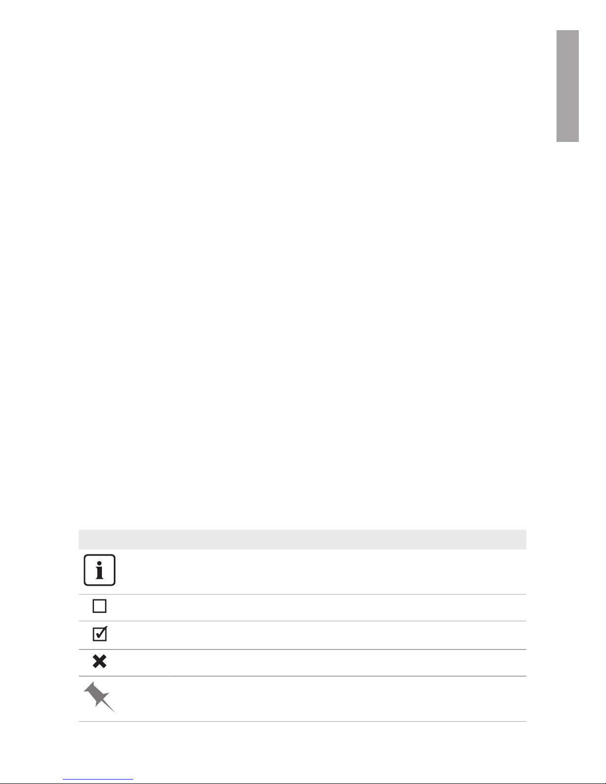
1.4 Symbols in the Document
Symbol Explanation
Information that is important for a specific topic or goal, but is not safety-relevant
Indicates a requirement for meeting a specific goal
Desired result
A problem that might occur
Example
ENGLISH
2 IMPORTANT SAFETY INSTRUCTIONS
SMA Solar Technology America LLC
Service ManualSBxx-1SP-US-40-AT-PU-SG-xx-124
2 IMPORTANT SAFETY INSTRUCTIONS
SAVE THESE INSTRUCTIONS
This section contains safety information that must be observed at all times when working on or with
the product.
The product has been designed and tested in accordance with international safety requirements. As
with all electrical or electronical devices, there are residual risks despite careful construction. To
prevent personal injury and property damage and to ensure long-term operation of the product,
read this section carefully and observe all safety information at all times.
DANGER
Danger to life due to electric shock when live components or DC conductors
are touched
When exposed to sunlight, the PV array generates dangerous DC voltage which is present in the
DC conductors and the live components of the inverter. Touching live DC conductors results in
death or lethal injuries due to electric shock.
• Disconnect the product from voltage sources and make sure it cannot be reconnected
before working on the device.
• Do not touch non-insulated parts or cables.
• Do not remove the terminal block with the connected DC conductors from the slot under
load.
• Wear suitable personal protective equipment for all work on the product.
DANGER
Danger to life due to electric shock when touching live system components in
case of a ground fault
If a ground fault occurs, parts of the system may still be live. Touching live parts and cables
results in death or lethal injuries due to electric shock.
• Disconnect the product from voltage sources and make sure it cannot be reconnected
before working on the device.
• Touch the cables of the PV array on the insulation only.
• Do not touch any parts of the substructure or frame of the PV array.
• Do not connect PV strings with ground faults to the inverter.
• Ensure that no voltage is present and wait five minutes before touching any parts of the PV
system or the product.
ENGLISH
2 IMPORTANT SAFETY INSTRUCTIONS
SMA Solar Technology America LLC
Service Manual SBxx-1SP-US-40-AT-PU-SG-xx-12 5
CAUTION
Risk of burns from hot surfaces
The surface of the inverter can get very hot. Touching the surface can result in burns.
• Mount the inverter in such a way that it cannot be touched inadvertently.
• Do not touch hot surfaces.
• Wait 30 minutes for the surface to cool sufficiently.
• Observe the safety messages on the inverter.
NOTICE
Damage to the enclosure seal in subfreezing conditions
If you open the product when temperatures are below freezing, the enclosure seals can be
damaged. Moisture can penetrate the product then.
• Only open the product if the ambient temperature is not below 0°C (32°F).
• If a layer of ice has formed on the enclosure seal when temperatures are below freezing,
remove it prior to opening the product (e.g. by melting the ice with warm air). Observe the
applicable safety regulations.
• Do not disassemble the PowerUnit unless the ambient temperature is at least 0°C (32°F)
and conditions are frost-free.
NOTICE
Damage to the product due to sand, dust and moisture ingress
Sand, dust and moisture penetration can damage the product and impair its functionality.
• Only open the product if the humidity is within the thresholds and the environment is free of
sand and dust.
• Do not open the product during a dust storm or precipitation.
• Close tightly all enclosure openings.
• Only use listed rain-tight or liquid-tight conduit fittings to attach the conduits to the product.
• Only disassemble the PowerUnit if a new PowerUnit is already available.
NOTICE
Damage due to cleaning agents
The use of cleaning agents may cause damage to the product and its components.
• Clean the product and all its components only with a cloth moistened with clear water.
NOTICE
Damage to the inverter due to electrostatic discharge
Touching electronic components can cause damage to or destroy the inverter through
electrostatic discharge.
• Ground yourself before touching any component.
ENGLISH

2 IMPORTANT SAFETY INSTRUCTIONS
SMA Solar Technology America LLC
Service ManualSBxx-1SP-US-40-AT-PU-SG-xx-126
Electrical installations (only applies to North America)
All electrical installations must be carried out in accordance with the local standards and the
National Electrical Code® ANSI/NFPA 70 or the Canadian Electrical Code® CSA C22.1.
• Before connecting the inverter to the utility grid, contact your local grid operator. The
electrical connection of the inverter must be carried out by qualified persons only.
• Ensure that no cables used for electrical connection are damaged.
ENGLISH
3 Overview of the Enclosure Parts
SMA Solar Technology America LLC
Service Manual SBxx-1SP-US-40-AT-PU-SG-xx-12 7
3 Overview of the Enclosure Parts
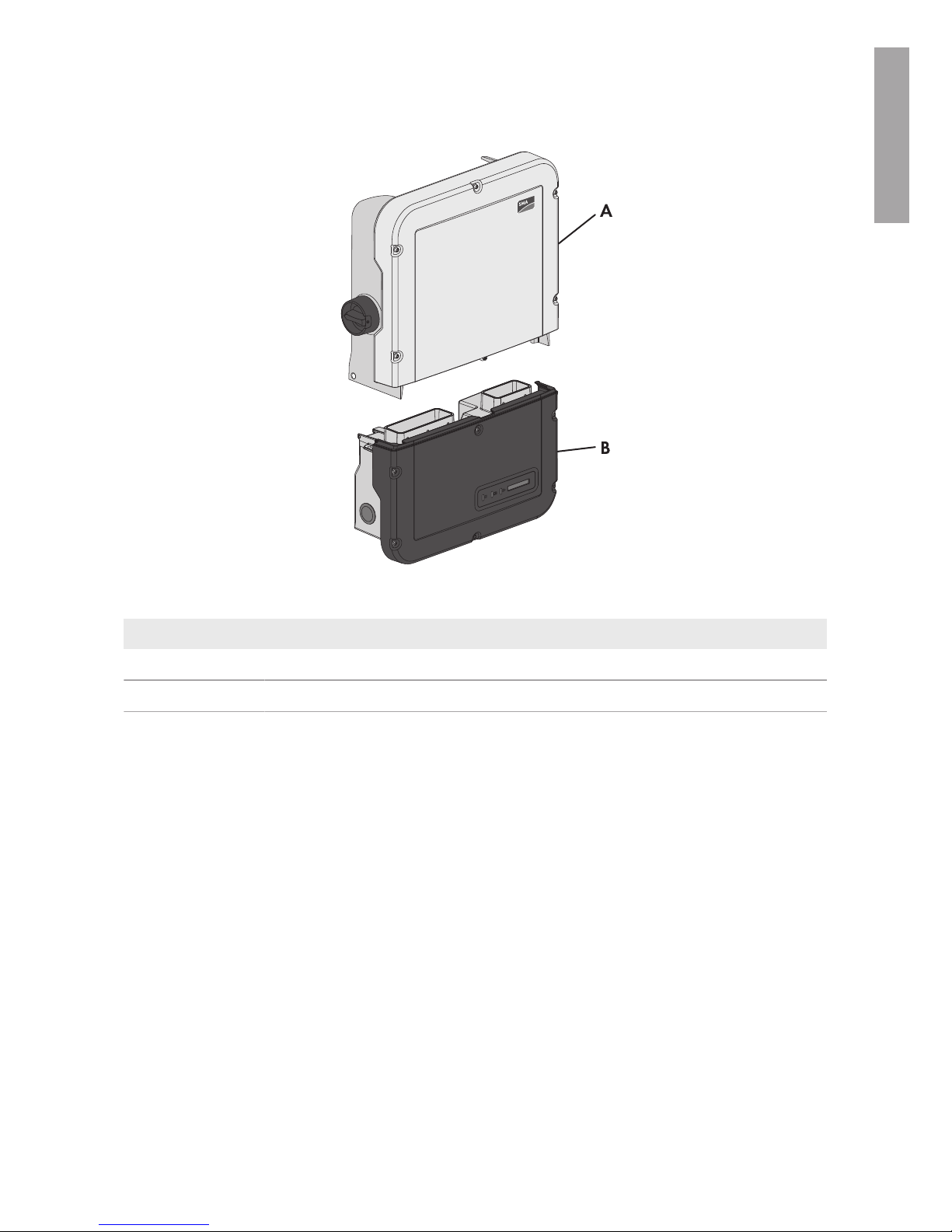
Figure 1 : Overview of the enclosure parts
Position Designation
A Power Unit
B Connection Unit
ENGLISH
4 Disassembling the Defective Power Unit
SMA Solar Technology America LLC
Service ManualSBxx-1SP-US-40-AT-PU-SG-xx-128
4 Disassembling the Defective Power Unit
Prior to disassembling the defective Power Unit, all connections between the Power Unit and the
Connection Unit must be severed. Only then can the Power Unit be removed from the Connection
Unit. All cables connected to the communication assembly can remain plugged in and do not need
to be removed to disassemble the PowerUnit.
Procedure:
1.
DANGER
Danger to life due to high voltages
• Disconnect the inverter from voltage sources (see inverter manual).
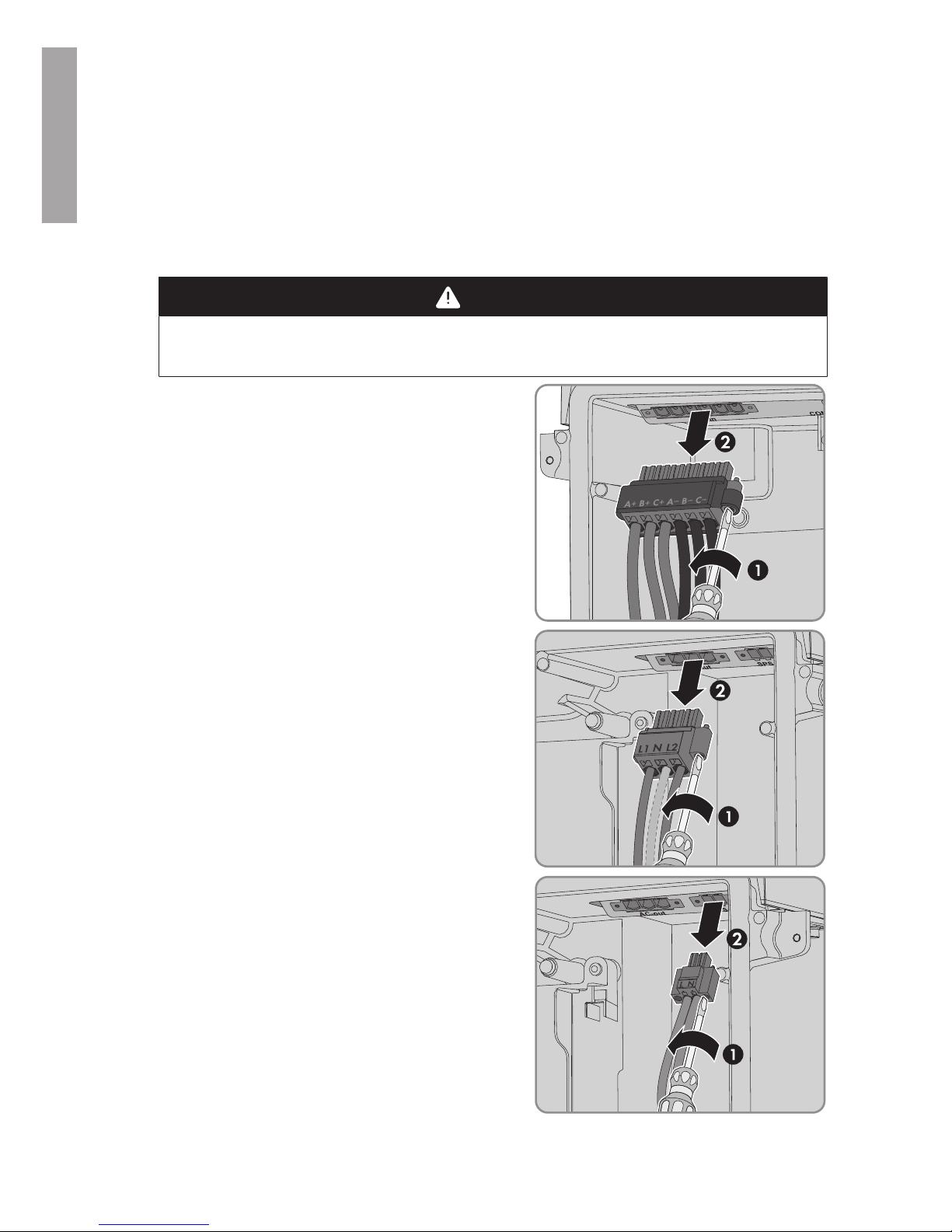
2. Remove the terminal block with the connected DC
conductors from slot DC-in. To do this, unscrew the
screws using a flat-blade screwdriver (blade width:
4mm (5⁄32in)) and pull the terminal block out of
the slot. While doing so, only touch the terminal
block on the black enclosure.
3. Remove the terminal block with the connected AC
conductors from slot AC-out. To do this, unscrew the
screws using a flat-blade screwdriver (blade width:
4mm (5⁄32in)) and pull the terminal block out of
the slot.
4. If there is a switch and an outlet for secure power
supply operation connected, remove the terminal
block with the connected cable from the SPS slot. To
do this, unscrew the screws using a flat-blade
screwdriver (blade width: 3.5mm) and pull the
terminal block out of the slot.
ENGLISH
4 Disassembling the Defective Power Unit
SMA Solar Technology America LLC
Service Manual SBxx-1SP-US-40-AT-PU-SG-xx-12 9
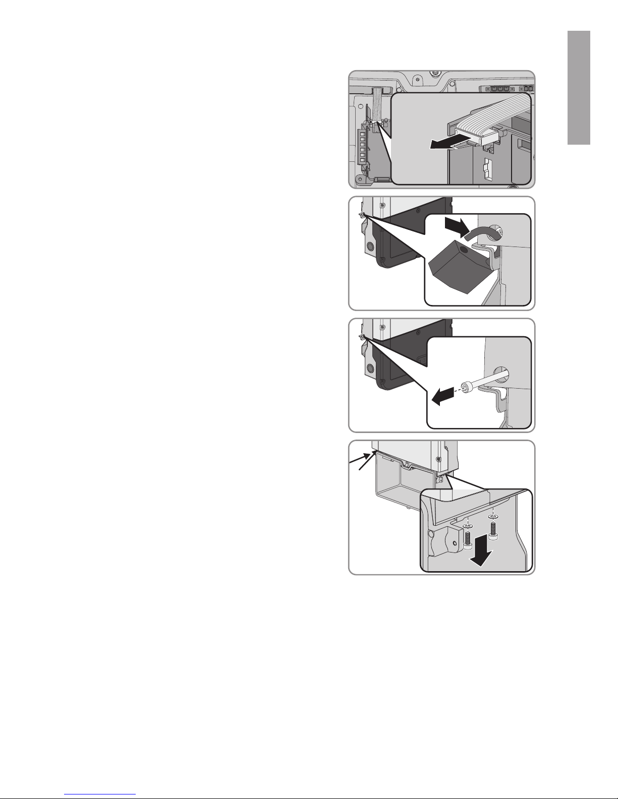
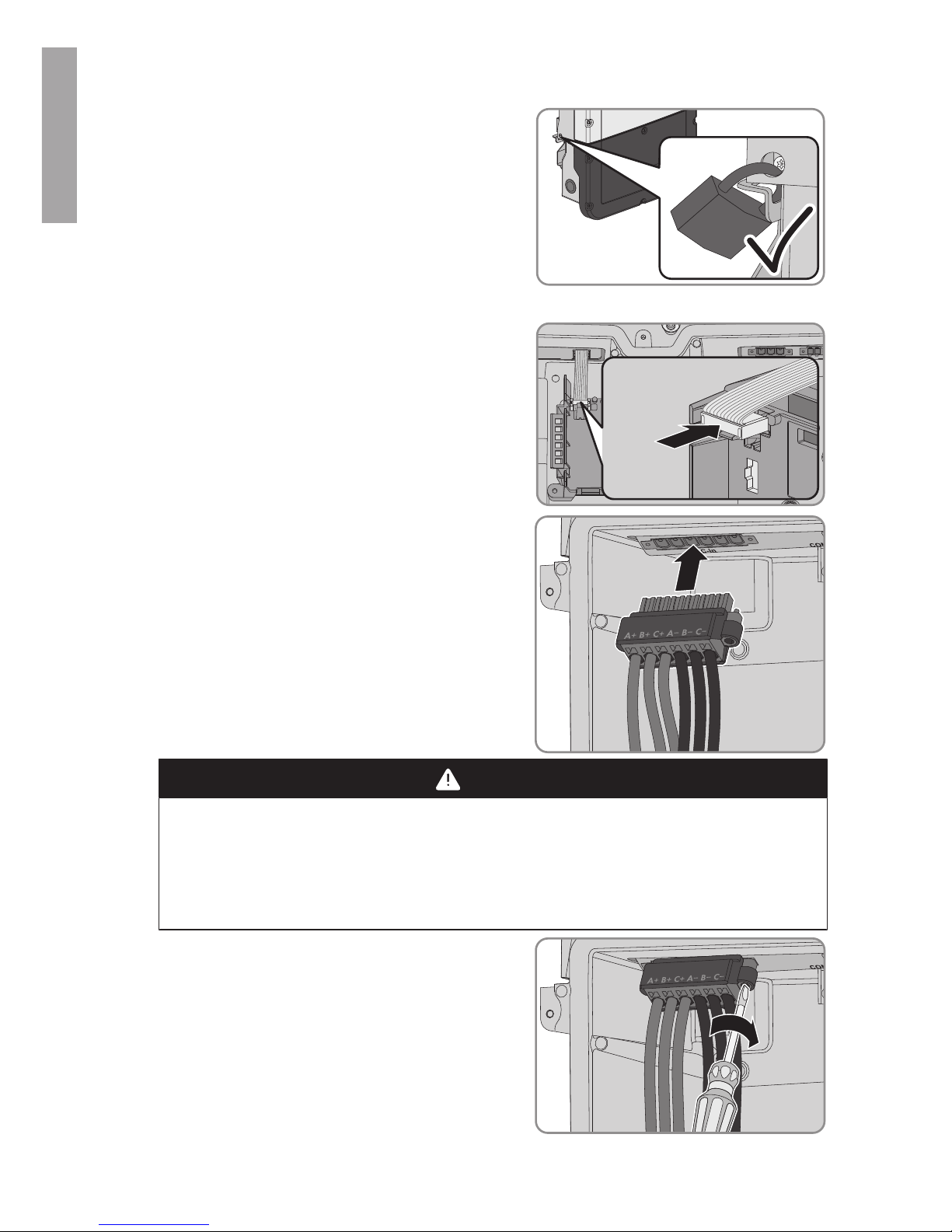
5. Pull the ribbon cable connecting the communication
assembly to the PowerUnit out of the
communication assembly.
COM
SPS
AC-out
D-IN
SPS
A B
M1
X1 X2
M2
ANT.
FCC ID: SVF-KP20
IC: 9440A-KP20
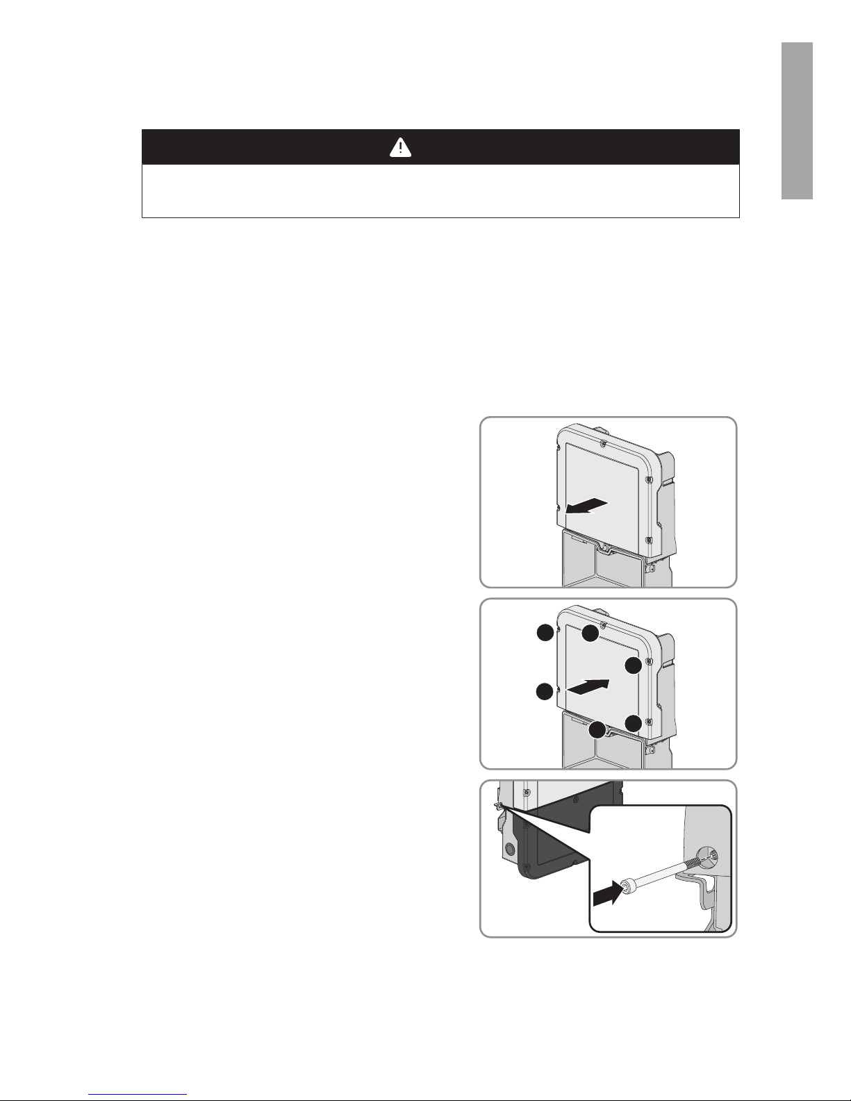
6. If the inverter is fitted with a padlock for theft
protection, open the padlock and remove it.
7. Unscrew the screw M5x60 that fastens the inverter
to the wall mounting bracket (TX25).
8. Unscrew the two screws on the right and left side of
the PowerUnit (TX25) and retain together with the
washers for later use.
ENGLISH
4 Disassembling the Defective Power Unit
SMA Solar Technology America LLC
Service ManualSBxx-1SP-US-40-AT-PU-SG-xx-1210
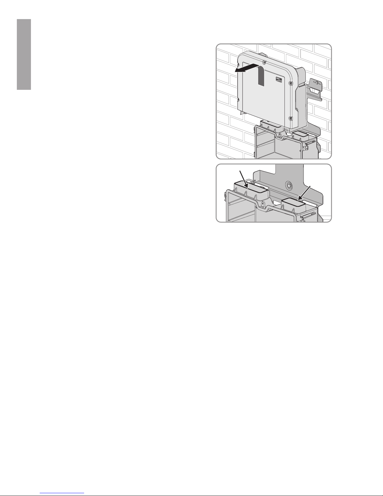
9. Lift to remove the Power Unit out of the wall
mounting bracket, thus separating the Power Unit
from the Connection Unit.
T
OP
10. If necessary, remove residual insulation material
from the two connection openings at the top of the
Connection Unit.
ENGLISH
5 Mounting the New Power Unit
SMA Solar Technology America LLC
Service Manual SBxx-1SP-US-40-AT-PU-SG-xx-12 11
5 Mounting the New Power Unit
1.
DANGER
Danger to life due to high voltages
• Disconnect the inverter from voltage sources (see inverter manual).
2. Hook the new Power Unit into the upper recesses of the wall mounting bracket, thus plugging
the Power Unit into the Connection Unit. Make sure that the screw holes on the left and right
sides of the PowerUnit are directly over those of the ConnectionUnit; and the cables
protruding from the PowerUnit must not be pinched.
3. Tighten two screws with two washers on the right and left side of the PowerUnit (TX25)
(torque: 6Nm ± 0.3Nm (53in-lb ± 2.65in-lb)).
4. If the enclosure lid of the new Power Unit is a transport lid (see information on the enclosure
lid), replace the transport lid of the new Power Unit with the enclosure of the defective Power
Unit:
• Unscrew all screws of the upper enclosure lid
(TX25) and remove it.
• Position the upper enclosure lid with the six
screws and serrated conical spring washers on
the enclosure and tighten it in the specified
order (TX25, torque: 6Nm (53in)).
1
2
3
4
5
6
5. Secure the inverter to the wall mounting bracket. To
do this, insert the screw M5x60 through the hole on
the left side of the PowerUnit and screw it into the
thread (TX25, torque: 1.7Nm ± 0.3 Nm (15.05inlb ± 2.65in-lb)).
6. If the inverter is to be protected against theft, attach a padlock:
ENGLISH
5 Mounting the New Power Unit
SMA Solar Technology America LLC
Service ManualSBxx-1SP-US-40-AT-PU-SG-xx-1212
• To do this, guide the shackle of the padlock
through the provided hole on the left side of the
Power Unit and close the shackle.
• Keep the key of the padlock in a safe place.
7. Pull the ribbon cable used to connect the
communication assembly to the PowerUnit into the
ConnectionUnit, and plug it into the jack on the
communication assembly.
COM
SPS
AC-out
D-IN
SPS
A B
M1
X1 X2
M2
ANT.
FCC ID: SVF-KP20
IC: 9440A-KP20
8. Plug the terminal block with the connected DC
conductors into slot DC-in in the Connection Unit.
While doing so, only touch the terminal block on the
black enclosure.
9.
DANGER
Danger to life due to electric arc
The terminal block must be fastened to the slot with two screws. If the terminal block is not
correctly mounted and comes out of the slot, an electric arc can form. An electric arc can
cause life-threatening injuries.
• Mount the terminal block on the slot as described in the following.
10. Tighten (torque: 1.7Nm ± 0.3 Nm (15.05in-lb ±
2.65in-lb)) the screws of the terminal block using a
flat-blade screwdriver (blade width: 3.5mm).
ENGLISH
5 Mounting the New Power Unit
SMA Solar Technology America LLC
Service Manual SBxx-1SP-US-40-AT-PU-SG-xx-12 13
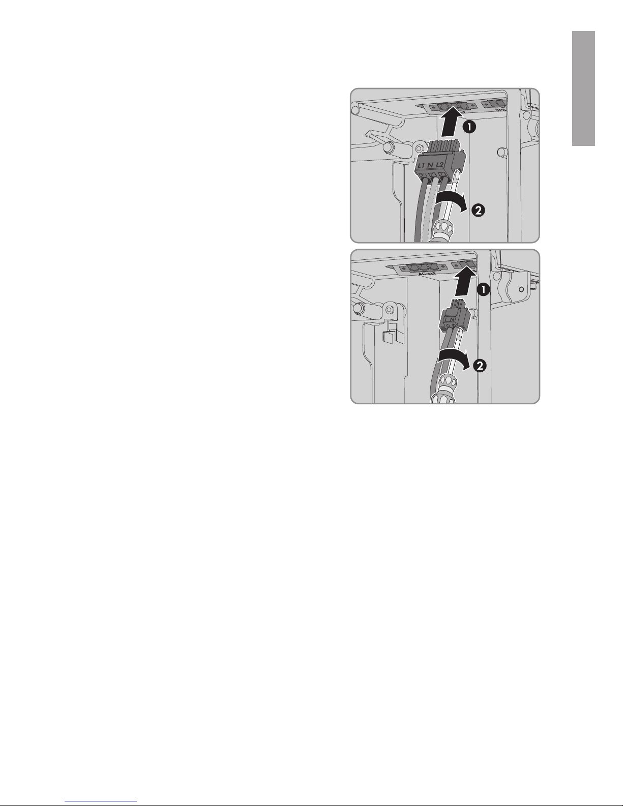
11. Ensure that the terminal block is securely in place.
12. Plug the terminal block with the connected AC
conductors into the AC-out slot in the
ConnectionUnit, and tighten (torque: 1.7Nm ± 0.3
Nm (15.05in-lb ± 2.65in-lb)) with a flat-blade
screwdriver (blade width: 3.5mm).
13. If applicable, plug the terminal block with the
connected cable for secure power supply operation
into the SPS slot in the Connection Unit, and tighten
(torque: 1.7Nm ± 0.3 Nm (15.05in-lb ± 2.65inlb)) with a flat-blade screwdriver (blade width:
3.5mm).
14. Commission the inverter (see inverter manual). The starting process of the inverter will take up
to 20 minutes since all relevant information is transferred from the ConnectionUnit to the
PowerUnit, and the PowerUnit may also be updated. Through the replacement of the Power
Unit, the inverter has been assigned a new serial number. The new serial number can be found
on the type label of the new Power Unit.
15. If the inverter is registered in a communication product (e.g. SunnyPortal), replace the inverter
in the communication product (see installation manual "Replacement of SMA Devices in
Systems with Communication Products" at www.SMA-Solar.com).
16. If the inverter firmware could not be updated prior to replacing the PowerUnit and the inverter
is not yet equipped with the current firmware version, perform a firmware update (see manual
of the inverter).
17. If a firmware update has been carried out, ensure that all parameters have been transferred
correctly and that the inverter feeds grid-compliant current into the utility grid.
ENGLISH

6 Packaging the Defective Power Unit for Pick-Up
SMA Solar Technology America LLC
Service ManualSBxx-1SP-US-40-AT-PU-SG-xx-1214
6 Packaging the Defective Power Unit for Pick-Up
1. Package the defective Power Unit for pick-up. Use the original packaging of the new Power
Unit for this purpose.
2. Arrange for pick-up by SMA. To do this, contact Service (refer to www.SMA-Solar.com for
contact details).
ENGLISH
 Loading...