

SLX 64 Element Digital TV Aerial Kit User Guid

64 Element Digital TV Aerial Kit
27985K4
USER GUIDE
Ready
Every aerial installation is dierent in nature. To t suitable brackets, xings and poles/masts you need to take into consideration:
a.) The state and type of surface being mounted to. b.) The weight of the assembly to be mounted. c.) The exposure to and eect of
prevailing winds.
Fixings and brackets supplied with this product may not be suitable for your particular installation.
The pole mount bracket and pole supplied with this product are recommended for loft mounting only. If in doubt please consult a CAI registered installer.
WARNING
Main Features
A. Rotating aerial elements, central
boom and centre mount assembly
B.Fittingthereectors
Congratulations on the purchase of your high gain wideband aerial kit which is designed to receive digital terrestrial signals.
This aerial is also 4G ready - the design restricts bandwidth to prevent interference & channel loss on your TV caused by signals from 4G transmitters.
This aerial has been manufactured to the standard required to get the best reception of digital terrestrial TV services (such as Freeview™). If the
aerial is to be used for DTT reception check before installation at www.dtg.org.uk/retailer/coverage.html to confirm that your home is in a coverage
area and to find out where your local transmitter is. This kit contains all the items necessary for central mounting the aerial to an existing mast or for
rear mounting externally to eaves or a wall or mounting in a loft. This kit also contains 10m of digital type coax cable to ensure good reception.
•
Wideband - suitable for all UK TV reception areas, covering UHF channels 21 to 60
•
Receives all digital TV signals on 470 - 790MHz
•
Perfect for use in the majority of locations although in very high strength signal areas an
attenuator may be required, or for very weak strength signal areas an amplifier may be needed
The aerial requires some assembly - please read these instructions carefully before beginning.
1. Rotate the elements about the central fixing clip until they
‘snap’ into an upright position as shown in Fig. 1.
2. The central boom comes in two sections using the bracket supplied and the
holes drilled in the boom sections join these two sections as shown in Fig. 2.
3. Attach centre mount bracket in the position shown using the clips supplied.
1. Using the reflector clamps, screw and large wing nut, fix
the reflector assemblies to the main aerial boom see Fig. 4.
2. Check that the reflector clamp tabs locate in the holes
of the reflector boom sections and that the wing nut
is tight - see Fig. 3.
engage
tab
in hole
reflector
element
reflector boom
assembly
reflector
clamps
rotate elements
element
in upright
position
central boom
back section
central boom
front section
joining bracket with
bolts and wing nuts
centre mount bracket
with clips, bolts and
wing nuts
Fig. 1
Fig. 2
Fig. 3
Fig. 4
fold braid back
over sheath
8mm
inner
wire
cut or tear
away foil
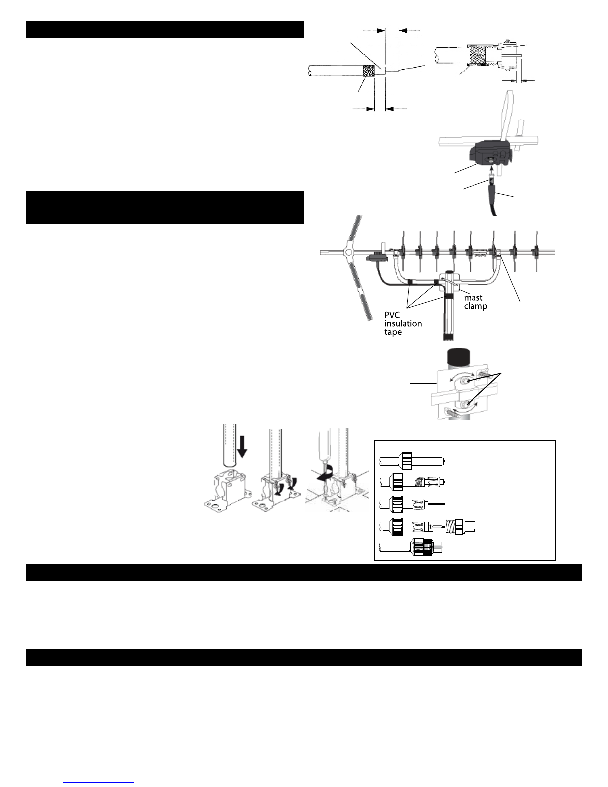
1. Before preparing and stripping cable ready for connection,
feed the aerial end of the coax cable through the weather boot.
2. Prepare cable as shown in Fig. 5. Fold the braid wires of the
cable back over the sheath and twist the F plug supplied
on to the cable. The inner wire of the cable should protrude
about 2 mm beyond the nut end of the plug see Fig. 6
3. To connect the cable to the aerial, offer up the cable, with ‘F’ plug
attached to the F socket on the bottom of the balun, ensuring that its inner
wire enters the socket’s centre contact. Screw the nut part of the plug onto the connector
body and tighten gently with a spanner (11 mm). Do not leave the connection finger tight
but do not over tighten as this could damage the balun. Finally, slide the waterproof sleeve
as far as it will go over the connector body, so that it butts up against the balun.
4 The other end of your cable can be fitted with a coax plug* to connect
to a TV/set top box etc. (see wiring instructions below), or wired to a
wall outlet* following manufacturers instructions. *Not supplied.
For optimum performance it is very important that the coax cable
should be routed as shown in Fig. 8. PVC insulation tape can be
used as shown to hold the cable in place. For best results the aerial
should be centre mounted on an outdoor aerial mast and pointed
in the direction of the nearest transmitter* making sure it is in a
position where the transmitter signal will not be obstructed by
nearby trees and buildings. If you are in any doubt about the
direction in which the aerial should be pointing or the orientation
of the aerial (horizontal for main transmitter, vertical for relay
transmitter) check your neighbours’ aerials. When centre mounting,
slide the aerial mount back and forth through the mast bracket to
find the most evenly balanced position, this will minimise the strain
on aerial, bracket and mast.
Before mounting check that the mast is in good condition and firmly fixed.
1. Using the clamp supplied fix the aerial to the mast - see Fig. 8 & 9 .
2. After the aerial direction has been fine tuned for best reception
tighten the bolts firmly until the aerial is securely fixed to the mast.
Alternatively, if there is enough space, your aerial can be loft mounted,
although this will cause some loss of signal strength.
Assemble the pole mount and mast
clamp as shown opposite (Figs 10, 11, 12).
The pole mount can be fitted to a roof
timber (using screws provided) or
to a suitably sound wall surface.
Centre
mount
bracket
1x Central boom: assembly square aluminium in 2 sections
joined, with 11x rotating ‘X’ type elements
2x Reflector booms: square aluminium with 8x reflector elements
1x Centre mount bracket with clips: assembly square aluminium
1x Bow tie shaped dipole & printed circuit balun with F connection
1x Tilting Mast Clamp
1x Loft mounting kit
1x Twist-on F plug with weather boot
10m Coax cable
Tilting
Mast Clamp
Adjust aerial
to horizontal
before
tightening
bolts
screw connector
body on to cable
2mm
approx.
end of
insulation
should be
flush with
this face
Balun
Weather
Boot
F Connector
C. Connecting coax cable
D. Coax cable routing and
xingaerialtoamast
Fig. 5 Fig. 6
Fig. 7
Fig. 8
Fig. 9
Customer Careline: 08457 573 479 (Local rate UK only)
Technical Website: www.philex.com/support
E-mail Support: technical@philex.com
CAUTION: When mounting the assembled aerial, always observe safety
precautions and use the correct equipment. Unless you are competent in the
use of ladders and other access equipment, do not work outdoors at roof
height. If in any doubt, refer to a qualified aerial installer.
Box contents
Coax plug wiring instructions
1 Unscrew coax plug housing and slide cap
over cable.
2 Strip 23mm of cable outer sheath.
Gather copper braid, wrap around outer
sheath, slide claw over braid and crimp.
3 Strip 18mm of inner insulation to leave 5mm
exposed
4 Undo screw on plug/clamp, slide clamp over
inner wire & tighten screw. Reassemble plug
1
2
3
4
5
5 Trim inner wire flush with plug.
Troubleshooting
© Philex Electronic Ltd 2013. v1 MK42 0NX
No picture: Check all connections from aerial to TV.
Poor picture: Check all connections from aerial to TV.
Check aerial is properly aligned to the correct transmitter.
If the aerial has been loft mounted try mounting outside.
Make sure new digital coax cable has been used throughout
the installation.
Check the transmitter signal is not obstructed by nearby trees
or buildings.
If in a weak signal area or for long cable runs, installing a masthead amplifier will improve the signal.
If in a strong signal area the signal strength may need to be
reduced by fitting an attenuator.
Useful Websites for Digital Advice
*To nd out what DTT channels should be available locally go
to: http://www.dtg.org.uk/industry/coverage.html
and enter postcode. To view your local transmitter’s distance
and compass bearing select “Trade view” from top bar.
Fig.10
Fig.11 Fig.12
Pole mount and pole are only suitable
for loft mounting this aerial -
not suitable for outside mounting
 Loading...