

SLX 28051R User Manual
28051R
Flat TV Screen Wall Mount 14 - 32” - Adjustable Tilt & Swivel
Main Features
USER GUIDE
• TV Size Range: 14 - 32”
• Maximum Weight Capacity: 20kg
• Mount Function: Adjustable Tilt & Swivel
• Wall to TV Distance: 90mm
• Compatible with VESA Sizes:
50 x 50, 75 x 75, 100 x 100, 200 x 100mm & 200 x 200mm
•
We have not supplied wall xings with this product. All walls dier in strength
and thickness. Consult a qualied installer or seek advice from your local
DIY/hardware store on purchasing suitable wall xings to safely mount the
bracket on the type of wall being used.
•
Check the contents list and images below to check there are no missing or
defective parts.
•
Never exceed the Maximum Weight Capacity shown above.
•
Read these instructions carefully before installation. If in any doubt about
safely installing this product, contact a professional installer for assistance.
•
This product was designed to be installed on wood stud walls and solid
concrete/brick walls. When xing to walls screws/bolts should be xed into
bricks/stone not into mortar courses.
•
Make sure the wall will support the combined load of the
equipment and hardware.
Also check for hidden wiring or plumbing.
•
Make sure that the heads of the screws/bolts you buy as wall fastenings are
the correct size to hold the bracket securely in position.
•
For larger/heavier TVs we recommend that you ask someone to assist you
with lifting and positioning your TV.
•
This product is suitable for indoor use only.
•
Improper installation or use of this product can result in product failure,
damage or personal injury.
•
This product contains small items that could cause choking if swallowed, so
keep these items away from children and pets.
•
Appropriate safety equipment and proper tools must be used for installation.
Always check manufacturer’s operating and safety instructions before using
tools and other equipment
WARNING
Components
M5 x 10
4pcs
M4 x 10
4pcs
Swivel/Tilt
Clamp
1pc
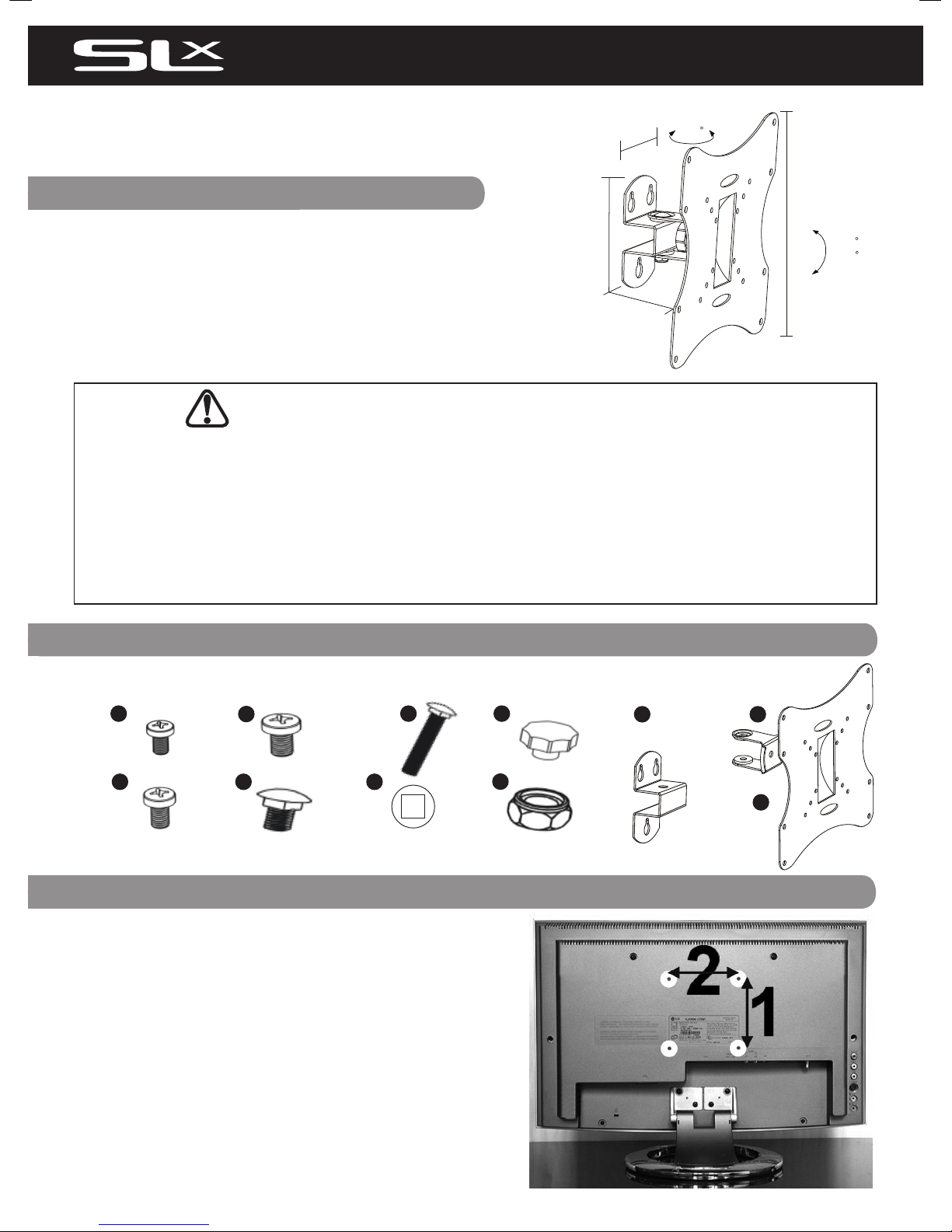
Wall Mount & VESA Compatibility
• VESA is the standard adopted by most TV manufacturers for wall
bracket mounting.
• There are 4 holes on the back of every at screen TV and the
space between the holes is governed by the VESA standard.
• VESA comes in a range of sizes depending on the weight and size
of the at screen TV; sizes 50 x 50mm, 75 x 75mm, 100 x 100mm,
100 x 200mm and so on... are standard. Not all at screen TVs are
compliant, contact the TV manufacturer for assistance if your TV
does not appear to comply with VESA.
• To check if your TV or monitor is compliant, look at the rear of
the display there should be 4 screw-holes in a square pattern or
in larger displays a rectangular shape. See Fig. 1 opposite, with
VESA mounting points shown in white circles.
• Measure the distances marked (2) (horizontal) x (1) (vertical) in
mm to nd your VESA format.
Fig. 1
Before installation check that you have all the components shown here and that
none of them are damaged.
Please Note wall xings are not supplied with this product.
M8 Washer
2pcs
M8 x 45
1pc
M8 Nut
1pc
Tilt/Clamp
Knob
1pc
Wall Bracket
1pc
TV Mounting
Plate
1pc
1
2
M8 x 16
1pcs
4 6
5 7
8
9 10
11
M6 x 10
4pcs
3
+20
-20
11 0mm
65 mm
90 mm
22 0m m
60
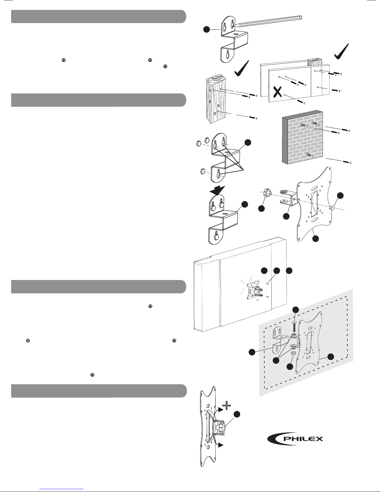
Fixing to Wood (Stud Walls)
The wall bracket ➒ is attached to the wall using three appropriate screws/
bolts two at the top and one below. Make sure the screws/bolts are
suitable for wood and large enough to support the weght of the TV and
bracket (if in doubt ask for advice at your local DIY/hardware store and
remember to make sure that the heads of the screws/bolts are the correct
size to hold the bracket securely in position).
As the uprights in stud walls are often quite thin the wall bracket ➒ has
been designed with two holes close together for mounting to wooden
uprights, see Fig. 3.
Mark and drill three holes into the wood as close as possible to the centre
of the upright.
To mark the holes, hold the bracket ➒ to the wall, using a
spirit level to make sure the bracket is level, and mark the centre of each
hole, see Fig. 2.
Drill the three holes. Attach the bracket ➒ to the wall
using the appropriate screws/bolts.
Tighten the screws/bolts in the positions shown in Fig. 3 and 4. Make sure
the screws are tight enough to hold the bracket ➒ ush to the wall but
loose enough to allow you to slide the bracket up and o the key slots.
Fixing to Concrete/Brick Walls
This process is similar to attaching to wood except that you will need
suitable screws/bolts/wall plugs for the type of wall you are mounting
onto (if in doubt ask for advice at your local DIY/hardware store and
remember to make sure that the heads of the screws/bolts are the correct
size to hold the bracket securely in position). When xing to walls screws/
bolts should be xed into bricks/stone not into mortar courses.
Step 2
Attach the swivel/tilt clamp ➓ to the TV mounting plate , see Fig 7.
Step 3
Check which size of the tting screws supplied ts your television (M4,
M5 or M6 ➊, ➋ or ➌). Then locate the tting holes on the mounting plate
that match your televisions mounting holes and attach the plate
rmly to the back of your television, see Fig. 8.
Step 4
Attach the wall bracket ➒ to the swivel/tilt clamp ➓ now attached to the
TV via the TV mounting plate , see Fig. 9.
Now that the mounting bracket is fully assembled and securely fastened
to the television, lift the TV and bracket assembly and align the keyhole
slots on the wall bracket ➒ (see Fig. 5 & 6) with the heads of all three
screws/bolts in the wall and slide the bracket ➒ down until it slots
securely into position.
If the television feels loose on the wall, lift the mount o the wall screws/
bolts and tighten them to decrease the gap between the screw/bolt head
and wall. Finally adjust the tilt and swivel to the required angle as shown
in Fig. 9.
PLEASE NOTE: It is recommended that especially with larger/heavier TVs
it is easier and safer if more than one person does any lifting required.
STEP 5 - Attaching the bracket and TV to the wall
Mounting your TV
Once you have decided where to locate your TV and where the bracket
needs to be positioned, mounting requires the 5 steps described below.
Step 1: mark and drill xing holes in the wall and attach the wall bracket
➒ to the wall using suitable screws/bolts, then slide the wall bracket o
the screws/bolts. Step 2 attach the swivel/tilt clamp ➓ to the TV
mounting plate . Step 3 attach the TV mounting plate to the TV.
Step 4 attach the swivel/tilt clamp and TV mounting plate ➓ &
assembly to the wall bracket ➒. Step 5 Lift the TV and bracket assembly
align the keyhole slots on the wall bracket ➒ with the heads of all three
screws/bolts in the wall and slide the bracket down securely into position.
Fig. 2
Fig. 3
Fig. 4
Fig. 5
Fig. 6
STEP 2 - 4 - Bracket Assembly
Fig. 10
Fig.7
7
4
Keyhole
Slots
STEP 1 - Preparing Wall Fixings
6
1
2
or
9
10
11
8
© Philex Electronic Ltd. 2010. V1.3
Fig. 8
For further information or any queries please contact
Customer Careline: 0901 293 0038
Calls are charged at £1 per minute from a BT landline.
Call charges from other networks may vary.
Technical Support: www.philex.com/support
-
+
Tilt Clamp
Rotate the tilt clamp knob anticlockwise (-)
while supporting the weight of the TV, tilt
the TV to the required position and turn
the knob ➐ clockwise to tighten and lock.
Tilt
Clamp
Knob
3
or
5
9
9
9
11
TV Screen
Back of TV
Fig. 9
7
 Loading...