

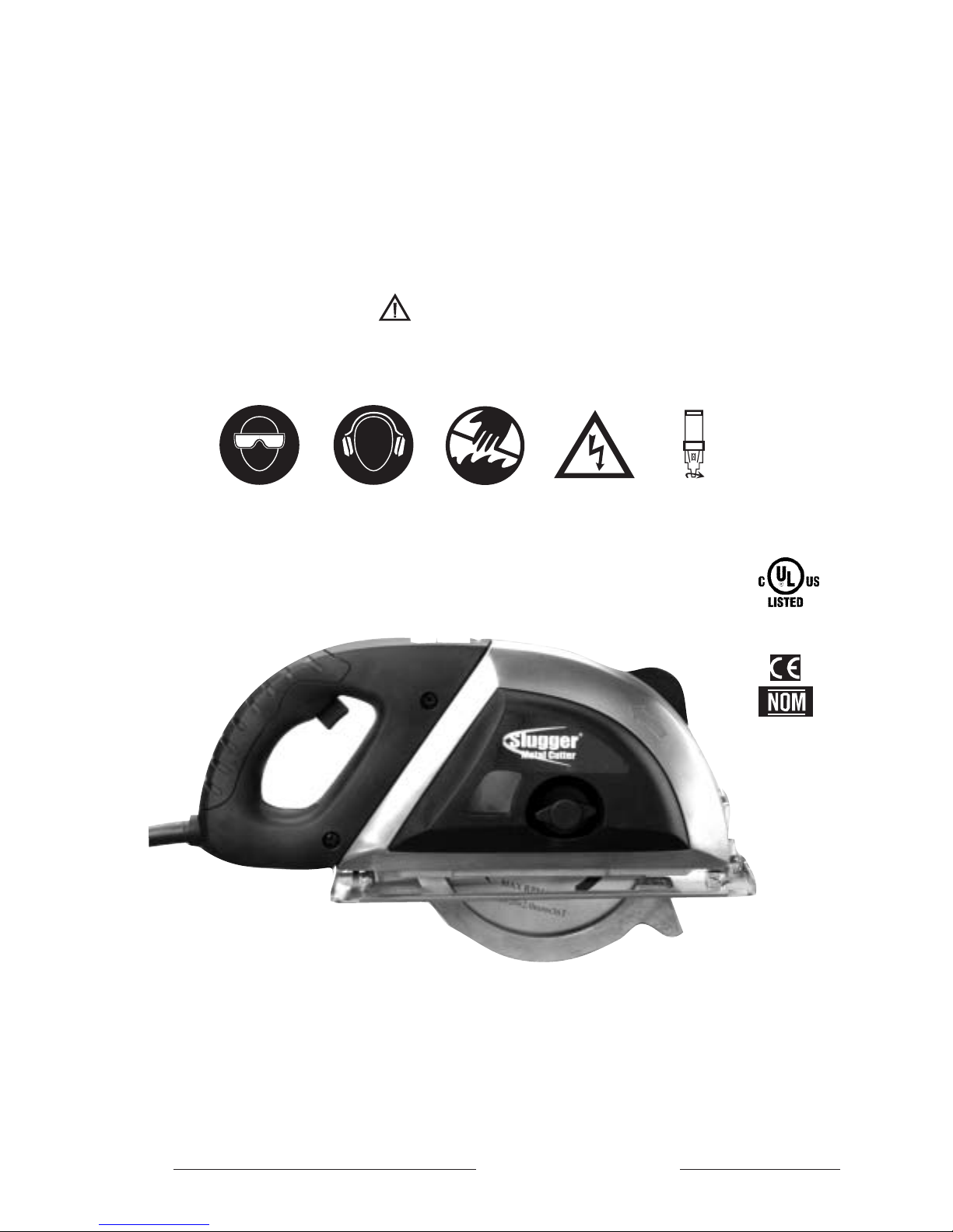
Slugger Metal Cutter
Portable Metal Cutting Saw
OPERATOR’S MANUAL
EYE PROTECTION
REQUIRED
HEARING PROTECTION
REQUIRED
MODEL #MCSL07 (120V)
MODEL #MCSL07-2 (240V)
Serial # Date of Purchase
WARNING!
BEFORE USE,
BE SURE EVERYONE USING THIS MACHINE READS AND UNDERSTANDS
ALL SAFETY AND OPERATING INSTRUCTIONS IN THIS MANUAL
.
NEVER PLACE
FINGERS NEAR
CUTTING AREA
LINE VOLTAGE
PRESENT
BEWARE OF
ROTATING
MACHINE PARTS
Metal Cutting Tool
7ZA6
E231568

Portable Metal Cutting Saw
Congratulations on your purchase of a Slugger Metal Cutter. Please take a moment to complete and mail your product
warranty registration card. Doing so will validate your machine’s warranty period and ensure prompt service if needed.
Thank you for selecting a product from Jancy Engineering Company.
TABLE OF CONTENTS
General Safety Rules and Specifications . . . . . . . . . . . . . . . . . . . . . . . . .3-4
Specific Safety Rules and Symbols . . . . . . . . . . . . . . . . . . . . . . . . . . . . .5-7
Functional Description . . . . . . . . . . . . . . . . . . . . . . . . . . . . . . . . . . . . . . .8
Assembly . . . . . . . . . . . . . . . . . . . . . . . . . . . . . . . . . . . . . . . . . . . . . . . .9
Exploded view . . . . . . . . . . . . . . . . . . . . . . . . . . . . . . . . . . . . . . . .10
Parts List . . . . . . . . . . . . . . . . . . . . . . . . . . . . . . . . . . . . . . . . . . . .11
Operation . . . . . . . . . . . . . . . . . . . . . . . . . . . . . . . . . . . . . . . . . . .12-13
Maintenance / Changing Saw Blades . . . . . . . . . . . . . . . . . . . . . . . . . . .14
Accessories . . . . . . . . . . . . . . . . . . . . . . . . . . . . . . . . . . . . . . . . . . . . .14
Troubleshooting Checklist . . . . . . . . . . . . . . . . . . . . . . . . . . . . . . . . . . . .15
Specifications . . . . . . . . . . . . . . . . . . . . . . . . . . . . . . . . . . . . . . . . . . . .16
JANCY ENGINEERING RESERVES THE RIGHT TO MAKE
IMPROVEMENTS AND MODIFICATIONS TO DESIGN WITHOUT PRIOR NOTICE.
LIMITED WARRANTY
Jancy Engineering Company will, within twelve (12) months from the original date of purchase, repair or replace any goods
found to be defective in materials or workmanship, provided the product warranty registration card has been returned to
Jancy Engineering Company within thirty (30) days of purchase date. This warranty is void if tool is used on materials
thicker than 3/8" (9.5 mm) solid for aluminum, 5/16" (8mm) for mild steel, or 1/4" (6.5 mm) for solid stainless steel, has
been damaged by accident, neglect, improper service, or other causes not arising out of defects in materials or workmanship. This warranty does not apply to machines and/or components which have been altered, changed, or modified in
any way, or subjected to use beyond recommended capacities and specifications. Electrical components are subject to
respective manufacturers’ warranties. All goods returned defective shall be returned prepaid freight to Jancy, which shall
be the buyer’s sole and exclusive remedy for defective goods. In no event shall Jancy Engineering be liable for loss or
damage resulting directly or indirectly from the use of merchandise or from any other cause. Jancy Engineering is not
liable for any costs incurred on such goods or consequential damages. No officer, employee or agent of Jancy is authorized to make oral representations of fitness or to waive any of the foregoing terms of sale and none shall be binding on
Jancy.
2
GENERAL SAFETY RULES
WARNING! Read and understand all instructions.
Failure to follow all instructions listed below, may result in electric shock, fire and/or serious personal injury.
SAVE THESE INSTRUCTIONS.
Work Area
•
Keep Your Work Area Clean and Well Lit.
•
Cluttered benches and dark areas invite accidents.
•
Do not operate power tools in explosive atmospheres, such as in the presence of flammable liquids, gases, or
dust. Power tools create sparks which may ignite the dust or fumes.
•
Keep bystanders, children, and visitors away while operating a power tool. Distractions can cause you to lose
control.
Electrical Safety
•
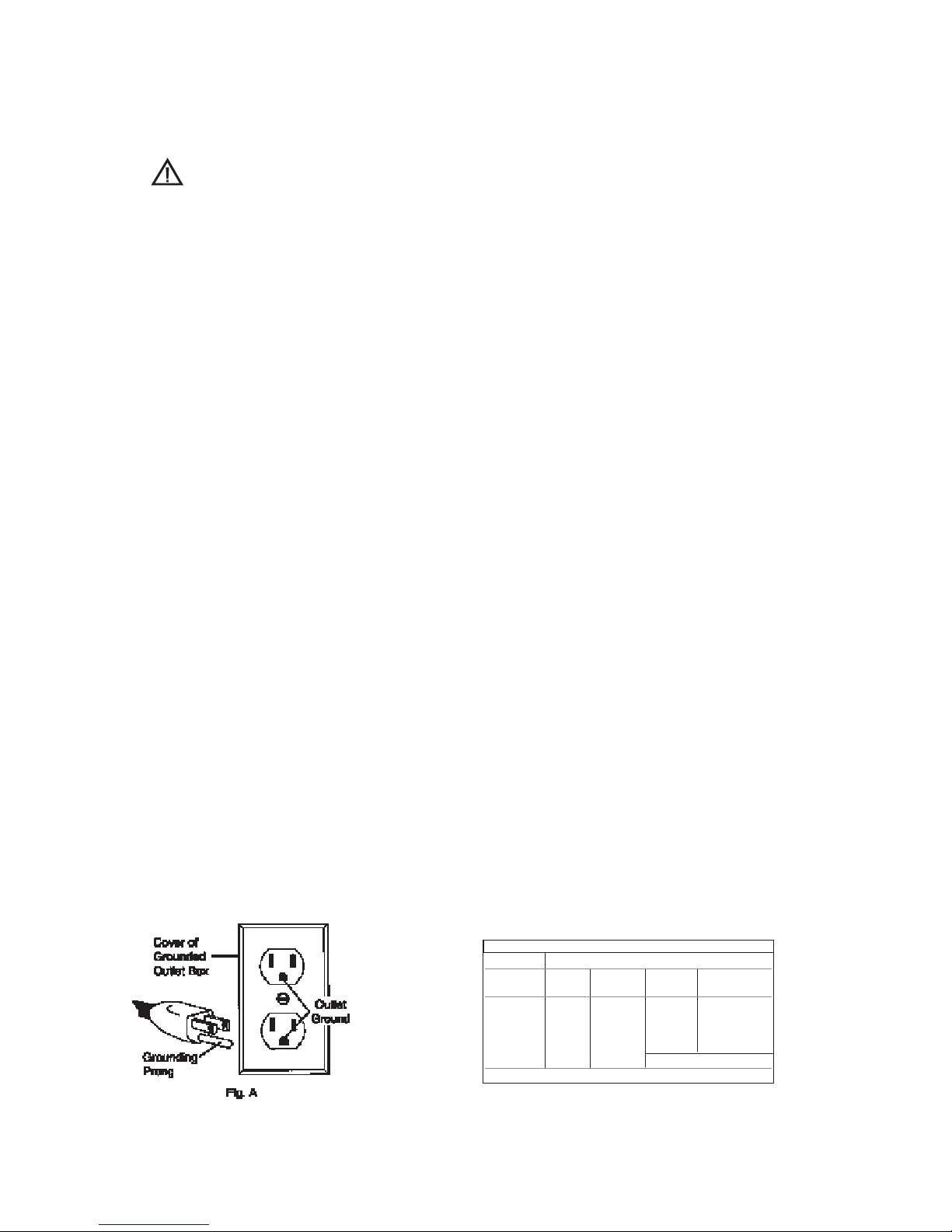
Grounded tools must be plugged into an outlet properly installed and grounded in accordance with all codes
and ordinances. Never remove the grounding prong or modify the plug in any way. Do not use any adaptor
plugs. Check with a qualified electrician if you are in doubt as to whether the outlet is properly grounded. If the
tools should electrically malfunction or break down, grounding provides a low resistance path to carry electricity
away from the user. (Refer to figure A below)
•
Avoid body contact with grounded surfaces such as pipes, radiators, ranges and refrigerators. There is an
increased risk of electric shock if your body is grounded.
•
Don't expose power tools to rain or wet conditions. Water entering a power tool will increase the risk of electric
shock.
•
Do not abuse the cord. Never use the cord to carry the tools or pull the plug from an outlet. Keep cord away
from heat, oil, sharp edges or moving parts. Replace damaged cords immediately. Damaged cords increase the
risk of electric shock.
•
When operating a power tool outside, use an outdoor extension cord marked "W-A" or "W." These cords are
rated for outdoor use and reduce the risk of electric shock.
(Note) When using an extension cord, be sure to use one heavy enough to carry the current your product will draw. An
undersized cord will cause a drop in line voltage resulting in loss of power and overheating. Jancy recommends using a
minimum 12 gauge extension cord not to exceed 100 feet. The table below (Figure B) is supplied only as a guide to
minimum gauge for extension cords, where the smaller the gauge number, the heavier the cord.
3
MINIMUM GAUGE FOR EXTENSION CORDS
VOLTS TOTAL LENGTH OF CORD IN FEET
120V 0-25 26-50 51-100 101-150
240V 0-50 51-100 101-200 201-300
AMPERAGE
0-6 18 16 16 14
6-10 18 16 14 12
10-12 16 16 14 12
12-16 14 12
NOT RECOMMENDED
RECOMMENDED WIRE GAUGE
*
JANCY RECOMMENDS USING A MINIMUM 12 GAUGE EXTENSION
CORD NOT TO EXCEED
100 FEET. FIG B.

Personal Safety
•
Stay alert, watch what you are doing and use common sense when operating a power tool. Do not use tool
while tired or under the influence of drugs, alcohol, or medication. A moment of inattention while operating
power tools may result in serious personal injury.
•
Dress properly. Do not wear loose clothing or jewelry. Contain long hair. Keep your hair, clothing, and gloves
away from moving parts. Loose clothes, jewelry, or long hair can be caught in moving parts.
•
Avoid accidental starting. Be sure switch is off before plugging in. Carrying tools with your finger on the switch
or plugging in tools that have the switch on invites accidents.
•
Remove adjusting keys or switches before turning the tool on. A wrench or a key that is left attached to a
rotating part of the tool may result in personal injury.
•
Do not overreach. Keep proper footing and balance at all times. Proper footing and balance enables better
control of the tool in unexpected situations.
•
Use safety equipment. Always wear eye protection. Dust mask, non-skid safety shoes, hard hat, or hearing
protection must be used for appropriate conditions.
Tool Use and Care
•
Use clamps or other practical way to secure and support the workpiece to a stable platform. Holding the work by
hand or against your body is unstable and may lead to loss of control.
•
Do not force tool. Use the correct tool for your application. The correct tool will do the job better and safer at the
rate for which it is designed.
•
Do not use tool if switch does not turn it on or off. Any tool that cannot be controlled with the switch is dangerous
and must be repaired.
•
Disconnect the plug from the power source before making any adjustments, changing accessories, or storing the
tool. Such preventive safety measures reduce the risk of starting the tool accidentally.
•
Store idle tools out of reach of children and other untrained persons. Tools are dangerous in the hands of
untrained users.
•
Maintain tools with care. Keep cutting tools sharp and clean. Properly maintained tools, with sharp cutting edges
are less likely to bind and are easier to control.
•
Check for misalignment or binding of moving parts, breakage of parts, and any other condition that may affect
the tools operation. If damaged, have the tool serviced before using. Many accidents are caused by poorly
maintained tools.
•
Use only accessories that are recommended by the manufacturer for your model. Accessories that may be suitable
for one tool, may become hazardous when used on another tool.
SERVICE
•
Tool service must be performed only by qualified repair personnel. Service or maintenance performed by
unqualified personnel could result in a risk of injury.
•
When servicing a tool, use only identical replacement parts. Follow instructions in the Maintenance section of this
manual. Use of unauthorized parts or failure to follow Maintenance Instructions may create a risk of electric shock or
injury.
GENERAL SAFETY RULES (cont.)
4
1. If you require an additional manual, please contact Jancy Engineering at (563) 391-1300 for a FREE copy.
2. Only use specified and approved saw blades.
3. Keep saw blades securely fastened.
4. Do not use dull or broken blades.
5. Beware of chips ejected. They become HOT during the cut.
6. Always make safe provisions for handling of excess material.
7. Keep bottom of base plate free from dirt and other debris.
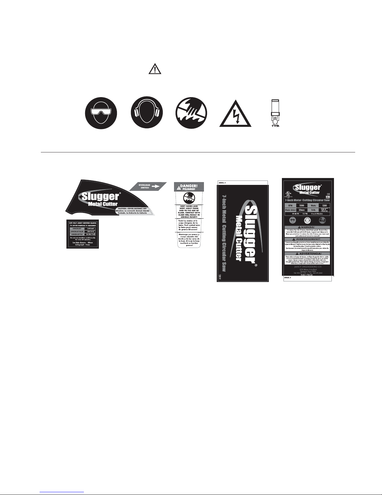
WARNING!
DO NOT OPERATE MACHINE IF WARNING AND/OR INSTRUCTION LABELS ARE MISSING OR DAMAGED.
CONTACT JANCY ENGINEERING FOR REPLACEMENT LABELS.
SPECIFIC SAFETY RULES AND SYMBOLS
5
EYE PROTECTION
REQUIRED
HEARING PROTECTION
REQUIRED
NEVER PLACE
FINGERS NEAR
CUTTING AREA
LINE VOLTAGE
PRESENT
BEWARE OF
ROTATING
MACHINE PARTS
V .............................................volts
A ............................................amperes
Hz ...........................................hertz
min ..........................................minutes
s .............................................seconds
~............................................alternating current
no...........................................no load speed

- DANGER! — Keep hands and body away from and to the side of the blade. Contact with blade will result in serious
injury.
- WARNING! — To reduce the risk of injury, check lower guard. It must close instantly! Hold saw with both hands.
Support and clamp work. Wear eye protection.
Additional Specific Safety Rules:
DANGER! Keep hands away from cutting area and blade. Keep your second hand on auxiliary handle, or motor
housing. If both hands are holding the saw, they cannot be cut by the blade.
•
Keep your body positioned to either side of the saw blade, but not in line with the saw blade. KICKBACK could
cause the saw to jump backwards. (See "Causes and Operator Prevention of Kickback.")
•
Do not reach underneath the work. The guard can not protect you from the blade below the work.
•
Check lower guard for proper closing before each use. Do not operate saw if lower guard does not move freely and
close instantly. Never clamp or tie the lower guard into the open position. If saw is accidentally dropped, lower guard
may be bent. Raise the lower guard and make sure it moves freely and does not touch the blade or any other part, in
all angles and depths of cut.
•
Check the operation and condition of the lower guard spring. If the guard and the spring are not operating properly,
they must be serviced before use. Lower guard may operate sluggishly due to damaged parts, gummy deposits, or a
buildup of debris.
•
Always observe that the lower guard is covering the blade before placing saw down on bench or floor. An
unprotected, coasting blade will cause the saw to walk backwards, cutting whatever is in its path. Be aware of the time
it takes for the blade to stop after switch is released.
•
NEVER hold piece being cut in your hands or across your leg. It is important to support the work properly to minimize
body exposure, blade binding, or loss of control.
•
Hold tool by insulated gripping surfaces when performing an operation where the cutting tool may contact hidden
wiring or its own cord. Contact with a "live" wire will also make exposed metal parts of the tool "live" and shock the
operator.
•
When ripping always use a rip fence or straight edge guide. This improves the accuracy of cut and reduces the
chance for blade binding.
•
Always use blades with correct size and shape (diamond vs. round) arbor holes. Blades that do not match the
mounting hardware of the saw will run eccentrically, causing loss of control.
•
Never use damaged or incorrect blade washers or bolts. The blade washers and bolt were specially designed for
your saw, for optimum performance and safety of operation.
SPECIFIC SAFETY RULES (cont.)
6

CAUSES
AND OPERA
TOR PREVENTION OF KICKBACK:
Kickback is a sudden reaction to a pinched, bound or misaligned saw blade, causing an uncontrolled saw to lift up
and out of the workpiece toward the operator. When the blade is pinched or bound tightly by the kerf closing
down, the blade stalls and the motor reaction drives the unit rapidly back toward the operator. If the blade becomes
twisted or misaligned in the cut, the teeth at the back edge of the blade can dig into the top surface of the material
causing the blade to climb out of the kerf and jump back toward operator. Kickback is the result of tool misuse
and/or incorrect operating procedures or conditions and can be avoided by taking proper precautions as given
below:
Maintain a firm grip with both hands on the saw and position your body and arm to allow you to resist KICKBACK
forces. KICKBACK forces can be controlled by the operator, if proper precautions are taken.
When blade is binding, or when interrupting a cut for any reason, release the trigger and hold the saw motionless
in the material until the blade comes to a complete stop. Never attempt to remove the saw from the work or pull the
saw backward while the blade is in motion or KICKBACK may occur. Investigate and take corrective actions to
eliminate the cause of blade binding.
When restarting a saw in the workpiece, center the saw blade in the kerf and check that saw teeth are not engaged
into the material. If saw blade is binding, it may walk up or KICKBACK from the workpiece as the saw is restarted.
Support large panels to minimize the risk of blade pinching and KICKBACK. Large panels tend to sag under their
own weight. Supports must be placed under the panel on both sides, near the line of cut and near the edge of the
panel.
Do not use dull or damaged blade. Unsharpened or improperly set blades produce narrow kerf causing excessive
friction, blade binding and KICKBACK.
Blade depth and bevel adjusting locking levers must be tight and secure before making cut. If blade adjustment
shifts while cutting, it may cause binding and KICKBACK.
Use extra caution when making a "Pocket Cut" into existing walls or other blind areas. The protruding blade may
cut objects that can cause KICKBACK.
SPECIFIC SAFETY RULES (cont.)
7

FUNCTIONAL DESCRIPTION
8

Remove all contents from packaging and inspect to ensure no damage was incurred during shipping. Your Slugger Metal
Cutter package should also include the following:
ASSEMBLY
DESCRIPTION PART # QTY
OPERATOR’S MANUAL LIT113 1
EARPLUGS, 3M-1100 MC702301 1
SAFETY GOGGLES MC702302 1
HEX KEY, M6 058112 1
HEX KEY, M5 0070588 1
GUIDE HANDLE MC731510 1
7” STEEL BLADE (OPTIONAL) MCBL07 1
SAFETY VIDEO MC795103 1
CARRYING CASE MC731514 1
GETTING STARTED
CAUTION!
ALWAYS DISCONNECT THE SAW FROM POWER SOURCE BEFORE MAKING ADJUSTMENTS.
Refer to the "Functional Description" on page 8 and "Assembly" drawing on page 10. Assemble guide handle (item# 73)
to machine housing. If required, assemble edge guide (item# 74) to base plate (item# 54), and adjust fence gate to
desired position. Secure with thumb screw. If a blade has not been installed, install an authorized saw blade as detailed
in the "Changing Saw Blades" section (page 14).
9
USE ONLY JANCY CERTIFIED BLADES
TO AVOID DAMAGE TO MACHINE!
#MCBL07
#MCBL07ALM
#MCBLO7SS
(mild steel)
(aluminum)
(stainless Steel)
Do not use machine continuously
for over 30 minutes.
Saw blade diameter · 180mm
Cutting depth · 51mm

ASSEMBLY (cont.)
10

ITEM DESCRIPTION PART
# QTY
38 WASHER, FLAT M5 JIS B 1256 MC751142 3
39* POWER CORD, 16-3 SEOOW MC770501 1
POWER CORD, 1.5MM 250V C-EUROPE MC770505
40 SCR, CRPHMS M5 X 12 JIS B 1111 MC751107 1
41 STRAIN RELIEF MC770502 1
42 HANDLE, RIGHT SIDE MC731504 1
43 SCR, HHCS M5 X 16 JIS B 1180 MC751102 4
44 STRAIN RELIEF STRAP MC731515 1
45 SCR, TAPPING CRPH M3.9 X 16 JIS B 1115-AB MC751101 5
46 TRIGGER SWITCH MC772101 1
47* CIRCUIT BREAKER, 8 AMP 125 V MC772102 1
CIRCUIT BREAKER, 4 AMP 250 V MC772103
48 WIRE ASSEMBLY 16 AWG X 350MM RED MC770504 1
49 CAPACITOR, EMC FILTER MC790101 1
50 HANDLE, LEFT SIDE MC731505 1
51 SCR, TAPPING CRPH M3.9 X 22 JIS B 1115-AB MC751105 3
52 CHIP DEFLECTOR MC720113 1
53 SCR, FHSCS M4 X 10 DIN 7991 06771 1
54 BASE PLATE ASSEMBLY MC720121 1
55 CONNECTING ROD MC720201 1
56 BEVEL ANGLE GAGE MC720106 1
57 T-KNOB M8 X 18 STUD JIS B 1180 MC731516 1
58 M6 NYLOCK NUT MC751130 1
59 KNOB, DEPTH ADJUSTMENT MC731517 1
60 WASHER, FLAT M8 JIS B 1256 MC751116 2
61 WASHER, INNER BLADE DRIVE MC741802 1
62 BLADE (NOT INCLUDED) OPTIONAL 1
63 WASHER, OUTER BLADE DRIVE MC741801 1
64 WASHER, FLAT M8 OVERSIZE MC751104 1
65 SCR, SERR FLNG SHCS M8 X 16 MC751103 1
66 BLADE HOUSING MC710002 1
67 SCR, SHCS M6 X 40 JIS B 1176 0070527 2
68 WASHER, FLAT M6 JIS B 1256 MC751118 2
69 CHIP COLLECTOR MC710001 1
70 TRIM COVER MC731502 1
71 SIGHT GLASS MC731503 1
72 T-KNOB M8 X 32 STUD JIS B 1180 MC731501 1
73 GUIDE HANDLE MC731510 1
74 EDGE GUIDE MC720108 1
SAW PARTS LIST
ITEM DESCRIPTION PART
# QTY
1 MAIN FRAME MC710004 1
2 PLATE, SPINDLE BEARING SUPPORT MC710003 1
3 BEARING, BALL 6202 SHIELDED MC701126 1
4 SPINDLE MC751911 1
5SPACER 14 X 20 X 6.2 MC720110 1
6 KEY, SPINDLE MC751902 1
7GEAR, 44T MC751901 1
8 RETAINING RING, EXT M14 MC751113 1
9 BEARING, BALL 608 SHIELDED MC772013 1
10 WASHER, SERR C-SINK M5 JIS 1252-C MC751136 2
11 SCR, CRFHMS M5 X 12 JIS B 1111 0151186 2
12 BUMPER, BLADE GUARD MC731512 1
13 SCR, CRPHMS M6 X 25 JIS B 1111 MC751112 1
14 WASHER, BLADE GUARD SLIP MC720111 1
15 BLADE GUARD MC710005 1
16 WASHER, BLADE GUARD RETAINING MC751903 1
17 SCR, CRPHMS M4 X 12 JIS B 1111 MC751128 3
18 SPRING, BLADE GUARD RETURN MC751406 1
19 MOTOR HOUSING MC731508 1
20 BRUSH HOLDER MC731509 2
21 SCR, SSS M5 X 12 CUP POINT JIS B 1177 MC751123 2
22 MOTOR BRUSH MC772014 2
23 BRUSH CAP MC772015 2
24 WIRE ASSEMBLY 16 AWG X 550MM RED MC770503 1
25* FIELD - 120V MC772002 1
FIELD - 240V MC772004
26 WASHER, EXT SERR M5 JIS B 1252-B 06781 3
27 SCR, TAPPING CRPH M4.8 X 70 JIS B 1115-AB MC751109 2
28* ARMATURE - 120V MC772001 1
ARMATURE - 240V MC772003
29 BEARING, BALL 608 SEALED 04544 1
30 BEARING, BALL 6001 LU 04543 1
31 FAN SHROUD MC731507 1
32 SPINDLE LOCK MC720001 1
33 WIRE GUARD MC731506 1
34 SCR, CRPHMS M4 X 8 JIS B 1111 04820 1
35 WASHER, EXT SERR M4 JIS B 1252-B 06773 1
36 SCR, CRPHMS M5 X 40 JIS B 1111 MC751110 3
37 WASHER, SPRING LOCK M5 JIS B 1251 #2.5 0151534 7
*Different for 120 & 240 volt models.
WHAT YOU SHOULD KNOW BEFORE SAWING
1. Type of material to be cut, (which determines blade selection) thickness and position should all be determined to
ensure proper performance.
2. Remove any excessive mill scale or rust from surface to be cut.
3. Material that has been flame cut may have become heat treated and therefore difficult to cut. Avoid sawing near
such areas whenever possible.
11

1. After the cut, release trigger switch to “OFF” position. Wait until saw motor completely stops.
2. Place saw on secure and level surface.
AFTER THE CUT
12
WARNING!
NEVER START SAW MOTOR WITH CUTTING EDGE OF SAW BLADE CONTACTING WORK SURFACE
.
DO NOT RETRACT BLADE GUARD
(ITEM# 15) MANUALLY. GUARD RETRACTS AUTOMATICALLY.
7. Position saw base plate on work surface near desired cutting area.
8. Depress and hold trigger switch lockout mechanism (item# 46).
9. When ready, start saw motor by activating trigger switch (item# 46).
10. Slowly approach material edge and gently apply pressure until saw blade has established a cutting groove in the material.
11. During remainder of cut apply smooth, constant pressure without overloading saw motor.
WARNING!
THIS MACHINE
’S CIRCUITRY WILL AUTOMATICALLY SHUT THE SAW MOTOR OFF IF EXCESSIVE OVERLOAD IS MAINTAINED.
IF SAW MOTOR SHOULD STALL OR STOP BEFORE A COMPLETE CUT IS MADE ALWAYS REMOVE BLADE FROM MATERIAL
BEFORE ATTEMPTING TO RESTART MOTOR
. FAILURE TO DO SO COULD RESULT IN PERSONAL INJURY.
1. The surface you are working on should be clean and level, free from rust, scale, dirt and chips.
2. Adjust the base plate to the desired bevel angle by loosening and then re-tightening the T-knob (item# 57).
3. For long, straight cuts in sheet stock, position the edge guide to the desired width and secure with thumb screw.
4. Adjust base plate for proper cutting depth. Secure using depth adjustment knob (item# 59).
5. Connect machine to power source.
6. Firmly grasp guide handle and trigger handle switch (item# 46).
OPERATION

1. If the overload circuit breaker should trip (item #47), disconnect plug from power source.
2. Allow sufficient time for machine to cool down.
3. Depress overload circuit breaker reset switch. Call Jancy Engineering Company if circuit breaker continues to trip.
WHA
T TO DO IF OVERLOAD SHOULD TRIP
CHIP COLLECTOR
WARNING!
ALWAYS DISCONNECT THE SAW FROM POWER SOURCE BEFORE CHANGING BLADES
, CLEARING CHIPS OR MAKING ADJUSTMENTS
.
1. Remove the T-knob and flat washer securing chip collector.
2. Remove chip collector from side panel of saw.
3. Empty chip collector, using a chip brush to thoroughly remove chips and debris from saw body.
4. Install chip collector on saw and fasten securely using T-knob and flat washer.
OPERATION (cont.)
13

WARNING!
ALWAYS DISCONNECT THE SAW FROM POWER SOURCE BEFORE CHANGING BLADES
, CLEARING CHIPS OR MAKING ADJUSTMENTS.
CHANGING
SAW BLADES
1. Place saw on level, secure surface.
2. Remove two (2) saw blade housing screws and washers (item# 67 and item# 68).
3. Remove chip collector and blade housing (item # 66 and item 69).
4. Engage spindle lock (item# 32).
5. Using supplied 6mm allen wrench, loosen and remove spindle bolt and flat washer (item# 64 and item# 65).
6. Remove outer blade drive washer (item# 63) and saw blade.
7. Reverse process to install new blade.
MAINTENANCE
14
ACCESSORIES
THE FOLLOWING METAL CUTTER ACCESSORIES ARE AVAILABLE
Saw Blades Application Part #
For cutting mild steel to 5/16" MCBL07
For cutting aluminum to 3/8" MCBL07ALM
For cutting stainless steel to 1/4" MCBL07SS

MCSL07, MCSL07-2
1. Low Blade Life/Teeth Chipping
–Wrong blade for the type of material.
a. MCBL07 for mild steel up to 5/16” solid.
b. MCBL07ALM for aluminum up to 3/8” solid.
c. MCBL07SS for stainless steel up to 1/4” solid.
–Aggressive contact with blade into material. Let the blade do the work.
–Too much vibration due to insufficient clamping, worn or bent blade, or worn parts (see "Saw Vibrates" below).
2. Machine will not turn on
–Check overload. If it has been tripped, it will extend out. Push in after allowing saw to cool down to re-set.
(PN MC772102) Check continuity.
–Inspect power cord for damage. Check continuity. Replace if needed. (PN MC770501)
–Inspect brushes for excessive wear. Replace if needed. (PN MC7702014)
–Do not exceed 30 minutes run time without cool down of saw.
–Check trigger switch for continuity. Replace if needed. (PN 772101)
3. Losing Power
–Inspect brushes and replace if needed. Part # MC772014 (2)
–Extension cord too long. Limit cord length to 100’.
–Extension cord too thin. Use 12 AWG or larger.
4. Blade Guard Sticks
–Remove guard and remove any foreign material. Wipe any excess material from guard & face plate. If contact
surface of guard or face plate is galled, use emery cloth or fine sandpaper to smooth out surfaces. Guard must
move freely. Use light grease on mating contact surfaces to aid in movement.
–Check guard return spring for sufficient tension. Replace if spring is weak. (PN MC751406)
–Check guard for distortion. Replace if distorted or damaged. (PN 710005)
5. Blade Spins on Spindle
–Check for proper tightness and installation. Inspect Inner blade flange (PN MC741802) and outer blade flange
centering shoulder (PN MC74180) for wear or damage. If the flanges are allowed to slip too many times, they
will no longer hold the blade properly. Replace if wear is excessive.
–Check flange mating surfaces for flatness. Replace if excessive distortion exists.
–Check to ensure flat washer and lock washer are present between bolt head and outer blade flange.
6. Saw Vibrates
–Check blade for tightness.
–Inspect inner blade flange (PN MC741802) and outer blade flange (PN MC74180) centering shoulder for wear
or damage. Replace if needed.
–Check to ensure work is properly clamped. Both primary and drop piece can cause vibration.
–Check bevel lock and depth lock for tightness. (PN MC731516 and PN MC720103)
TROUBLESHOOTING CHECKLIST
SLUGGER 7"METAL CUTTER
15

YOUR DISTRIBUTOR
MANUFACTURER OF SLUGGER®CENTERFREE CUTTERS AND PORTABLE MAGNETIC DRILLING MACHINES
Tel · 563.391.1300 or Fax · 563.391.2323
2735 Hickory Grove Road · Davenport, Iowa 52804
email · jancy@jancy.com / web · jancy.com
LIT113
©2/03
DIMENSIONS AND SPECIFICATIONS
Height 239mm (9.4")
Width 269mm (10.59")
Length 422mm (16.61")
Weight 6.2 kg (13.6 lbs.)
Motor 120V - 1200W / 240V - 1200W
50~60 Hz / 3500 RPM
Blade Arbor 20mm (0.787")
Blade Diameter 180mm (7")
Depth of Cut/Pipe or Angle (maximum) 51mm (2")
Depth of Cut/Plate or Bar (maximum) 8mm Mild Steel (5/16")
9.5mm Aluminum (3/8")
6.5 Stainless Steel (1/4")
Case Dimensions 460mm H (18")
546mm W (21.5")
280mm D (11")
SPECIFICATIONS
 Loading...