

© C. & E. Fein GmbH. Printed in USA. Figure not obligatory. Subject to technical changes. 3 41 01 246 21 0 BY 2018.04.
by FEIN
by FEIN
USA
FEIN Power Tools, Inc.
1000 Omega Drive
Suite 1180
Pittsburgh, PA 15205
Phone: 800-441-9878
www.feinus.com
Canada
FEIN Canadian Power Tool
Company
323 Traders Boulevard East
Mississauga, Ontario L4Z 2E5
Telephone: (905) 8901390
Phone: 1-800-265-2581
www.fein.com
FEIN Service USA
FEIN Power Tools, Inc.
2735 Hickory Grove Road
Davenport, IA 52804
Phone: 800-441-9878
magdrillrepair@feinus.com
Headquarter
C. & E. Fein GmbH
Hans-Fein-Straße 81
D-73529 Schwäbisch Gmünd-Bargau
www.fein.com
JMU 137 QW (**) 7 270 ...
JMU 137 MQW (**) 7 270 ...
JMU 137-2 QW (**) 7 270 ...
OBJ_DOKU-0000006757-003.fm Page 1 Wednesday, April 4, 2018 9:31 AM
2
Instruction Manual
Mode d’emploi
Instrucciones de uso
en
3
fr29es
55
OBJ_BUCH-0000000261-003.book Page 2 Thursday, January 11, 2018 5:30 PM
3
en
en
For your safety.
Read all safety warnings and
all instructions. Failure to fol-
low the warnings and instructions may result
in electric shock, fire and/or serious injury.
Save all warnings and instructions for futurereference.
Do not use this power tool before you
have thoroughly read and completely
understood this Instruction Manual, including
the figures, specifications, safety regulations
and the signs indicating DANGER, WARNING and CAUTION.
Only carry out such operations with this
power tool as intended for by the manufacturer. Only use cutting tools and accessories
that have been approved by the manufacturer.
Please also observe the relevant national
industrial safety regulations.
Non-observance of the safety instructions in
the said documentation can lead to an electric
shock, burns and/or severe injuries.
This Instruction Manual should be kept for
later use and enclosed with the power tool,
should it be passed on or sold.
SAVE THESE INSTRUCTIONS.
The term “power tool” in the warnings refers
to your mains-operated (corded) power tool
or battery operated (cordless) power tool.
General safety rules.
1) Work area safety
a)Keep work area clean and well lit. Clut-
tered or dark areas invite accidents.
b)Do not operate power tools in explosive
atmospheres, such as in the presence of
flammable liquids, gases or dust. Power
tools create sparks which may ignite the
dust or fumes.
c) Keep children and bystanders away
while operating a power tool. Distrac-
tion can cause you to lose control.
2) Electrical safety
a)Power tool plugs must match the outlet.
Never modify the plug in any way. Do not
use any adapter plugs with earthed
(grounded) power tools. Unmodified
plugs and matching outlets will reduce
risk of electric shock.
b)Avoid body contact with earthed or
grounded surfaces such as pipes, radiators, ranges and refrigerators. There is
an increased risk of electric shock if
your body is earthed or grounded.
c) Do not expose power tools to rain or wet
conditions. Water entering a power
tool will increase the risk of electric
shock.
d)Do not abuse the cord. Never use the
cord for carrying, pulling or unplugging
the power tool. Keep cord away from
heat, oil, sharp edges or moving parts.
Damaged or entangled cords increase
the risk of electric shock.
e) When operating a power tool outdoors,
use an extension cord suitable for outdoor use. Use of a cord suitable for out-
door use reduces the risk of electric
shock.
f) If operating a power tool in a damp loca-
tion is unavoidable, use a ground fault
circuit interrupter (GFCI) protected supply. Use of an GFCI reduces the risk of
electric shock.
3) Personal safety
a)Stay alert, watch what you are doing
and use common sense when operating
a power tool. Do not use a power tool
while you are tired or under the influence of drugs, alcohol or medication. A
moment of inattention while operating
power tools may result in serious personal injury.
b)Use personal protective equipment.
Always wear eye protection. Protective
equipment such as dust mask, non-skid
safety shoes, hard hat, or hearing protection used for appropriate conditions
will reduce personal injuries.
c) Prevent unintentional starting. Ensure
the switch is in the off-position before
connecting to power source and/or battery pack, picking up or carrying the
tool. Carrying power tools with your
finger on the switch or energising
power tools that have the switch on
invites accidents.
WARNING
OBJ_BUCH-0000000261-003.book Page 3 Thursday, January 11, 2018 5:30 PM
4
en
d)Remove any adjusting key or wrench
before turning the power tool on. A
wrench or a key left attached to a rotating part of the power tool may result in
personal injury.
e) Do not overreach. Keep proper footing
and balance at all times. This enables
better control of the power tool in
unexpected situations.
f) Dress properly. Do not wear loose cloth-
ing or jewelery. Keep your hair, clothing
and gloves away from moving parts.
Loose clothes, jewelry or long hair can
be caught in moving parts.
g)If devices are provided for the connec-
tion of dust extraction and collection
facilities, ensure these are connected
and properly used. Use of dust collec-
tion can reduce dust-related hazards.
4) Power tool use and care
a)Do not force the power tool. Use the cor-
rect power tool for your application. The
correct power tool will do the job better and safer at the rate for which it was
designed.
b)Do not use the power tool if the switch
does not turn it on and off. Any power
tool that cannot be controlled with the
switch is dangerous and must be
repaired.
c) Disconnect the plug from the power
source and/or the battery pack from the
power tool before making any adjustments, changing accessories, or storing
power tools. Such preventive safety
measures reduce the risk of starting the
power tool accidentally.
d) Store idle power tools out of the reach of
children and do not allow persons unfamiliar with the power tool or these
instructions to operate the power tool.
Power tools are dangerous in the hands
of untrained users.
e) Maintain power tools. Check for mis-
alignment or binding of moving parts,
breakage of parts and any other condition that may affect the power tool’s
operation. If damaged, have the power
tool repaired before use. Many accidents
are caused by poorly maintained power
tools.
f) Keep cutting tools sharp and clean.
Properly maintained cutting tools with
sharp cutting edges are less likely to
bind and are easier to control.
g) Use the power tool, accessories and tool
bits etc. in accordance with these
instructions, taking into account the
working conditions and the work to be
performed. Use of the power tool for
operations different from those
intended could result in a hazardous situation.
5) Service
a)Have your power tool serviced by a qual-
ified repair person using only identical
replacement parts. This will ensure that
the safety of the power tool is maintained.
Special safety instructions.
Wear protective equipment. Depending on the
application, wear face shield or safety goggles. Wear hearing protection. The safety
glasses/goggles must be suitable to protect
against the particles emitted from different
operations. Continuous high exposure to
noise can lead to loss of hearing.
Do not touch the sharp edges of the core drill
bit. Danger of injury.
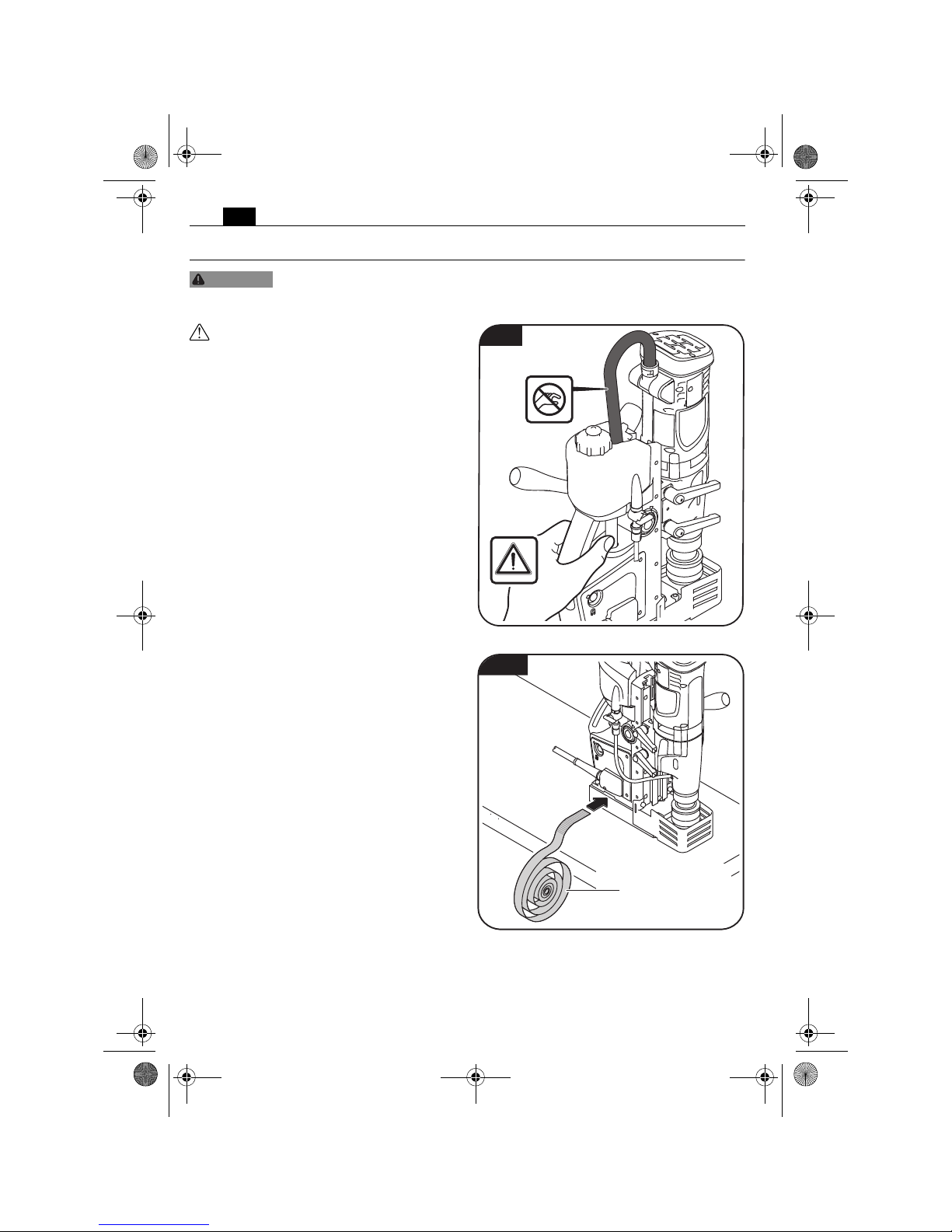
Replace the protective cable bushing immediately when damaged. A defective protective
cable bushing can lead to overheating of the
machine and to an emergency stop.
Before putting into operation: Mount the chip
guard to the machine.
Always secure the power tool with with the
supplied clamping strap. In case of a power
failure or when the power plug is pulled, the
magnetic holding power is not maintained.
When carrying out such work, beware of falling objects, such as cores or chips.
OBJ_BUCH-0000000261-003.book Page 4 Thursday, January 11, 2018 5:30 PM

5
en
When working overhead or on vertical surfaces, the coolant container must not be used.
Use Slugger Cutting Paste instead. Liquids
penetrating your electric power tool maycause electric shock.
Avoid touching the drilled core that is automatically ejected by the pilot pin when the
working procedure is finished. Contact with
the core when it is hot, or if it falls, can cause
personal injuries.
Operate the power tool only from grounded
contact sockets that comply with the specifications. Do not use any connection cables
that are damaged; use extension cables with
a grounded contact that are checked at regular intervals. A ground conductor without
continuity can cause an electric shock.
To prevent injuries, always keep your hands,
clothing, etc. away from rotating chips. The
chips can cause injuries. Always use the chip
guard.
Do not attempt to remove the cutting tool if it
still turns. This can lead to serious injuries.
Hold power tool by insulated gripping surfaces when performing an operation where
the cutting accessory may contact hidden
wiring or its own cord. Cutting accessory con-
tacting a “live” wire will make exposed metal
parts of the power tool “live” and shock the
operator.
Beware of any concealed electric cables, gas
or water conduits. Check the working area
before commencing work, e. g. with a metal
detector.
Do not work materials containing magnesium.
Danger of fire.
Do not work CFP (carbon-fiber-reinforced
polymer) and materials containing asbestos.
These materials are considered carcinogenic.
Do not rivet or screw any name-plates or
signs onto the power tool. If the insulation is
damaged, protection against an electric shock
will be ineffective. Adhesive labels are recommended.
Do not overload the power tool or the storage
case and do not use it as a ladder or stand.
Overloading or standing on the power tool or
the storage case can lead to the upward shifting of the center of gravity of the power tool
or the storage case, and its tipping over.
Do not use accessories which are not specifically designed and recommended by the
power tool manufacturer. Safe operation is
not ensured merely because an accessory fits
your power tool.
Clean the ventilation openings on the power
tool at regular intervals using non-metal
tools. The blower of the motor draws dust
into the housing. An excessive accumulation
of metallic dust can cause an electrical hazard.
Before putting into operation, check the
power connection and the power plug for
damage.
Recommendation: The tool should always be
supplied with power via a ground fault circuit
interrupter (GFCI) with a rated current of
30 mA or less.
OBJ_BUCH-0000000261-003.book Page 5 Thursday, January 11, 2018 5:30 PM
6
en
Handling hazardous dusts.
When working with power
tools, such as when grinding,
sanding, polishing, sawing or for other work
procedures where material is removed, dusts
develop that are both hazardous to one’s
health and can spontaneously combust or be
explosive.
Contact with or inhaling some dust types can
trigger allergic reactions to the operator or
bystanders and/or lead to respiratory infections, cancer, birth defects or other reproductive harm.
Examples of such materials which contain
chemicals that can produce hazardous dusts,
are:
– Asbestos and materials containing asbes-
tos;
– Lead-containing coatings, some wood
types such as beech and oak;
– Minerals and metal;
– Silicate particles from bricks, concrete and
other materials containing stone;
– Solvent from solvent-containing paint/
varnish;
– Arsenic, chromium and other wood pre-
servatives;
– Materials for pesticide treatment on boat
and ship hulls;
– Stainless steel dust, metal dust and non-
ferrous metal dust;
To minimize the unwanted intake of these
materials:
– Use dust extraction matched appropriately
for the developing dust.
– Use personal protective equipment, such
as a P2 filter-class dust protection mask.
– Provide for good ventilation of the work-
place.
The risk from inhaling dusts depends on how
often these materials are worked. Materials
containing asbestos may only be worked on
by specialists.
Wood and light-metal dust can
cause spontaneous combustion or explosions.
Hot mixtures of sanding dust and paint/varnish residuals or other chemical materials in
the filter bag or the vac filter can self-ignite
under unfavourable conditions, such as sparking from sanding metal, continuous sunlight
or high ambient temperatures. To prevent
this:
– Avoid overheating the material being
sanded and the power tool.
– Empty the dust collector/container rou-
tinely.
– Observe the material manufacturer’s
working instructions.
– Observe the relevant regulations for the
materials being worked.
WARNING
CAUTION
OBJ_BUCH-0000000261-003.book Page 6 Thursday, January 11, 2018 5:30 PM
7
en
Emission values for sound (Two-figure – specifications as per ISO 4871)
Extension cable.
If the use of an extension cord
is required, its length and conductor cross-section must be adequate for the
application in order to prevent a voltage drop
in the extension cord, power loss and overheating of the power tool. Otherwise, the
extension cable and power tool are prone to
electrical danger, and the working efficiency is
decreased.
Sound emission JMU 137 QW (**) JMU 137 MQW (**) JMU 137-2 QW (**)
A-weighted emission
pressure power level measured at the workplace
L
pA
(re 20 μPa), in deci-
bels 86.7 86.7 85.6
Measuring uncertainty
K
pA
, in decibels 3 3 3
Measured A-weighted
sound power level
L
wA
(re 1 pW), in decibels 97.7 97.7 96.6
Measuring uncertainty
K
wA
, in decibels 3 3 3
C-weighted peak sound
pressure level measured at
the workplace
L
pCpeak
, in
decibels 101.2 101.2 98.9
Measuring uncertainty
K
pCpeak
, in decibels 3 3 3
Mean vibrational value
(core drilling)
– m/s
2
– ft/s
2
< 2.5
8.3
< 2.5
8.3
< 2.5
8.3
Measuring uncertainty
K
,
in
– m/s
2
– ft/s
2
1.5
4.9
1.5
4.9
1.5
4.9
REMARK: The sum of the measured emission value and respective measuring inaccuracy
represents the upper limit of the values that can occur during measuring.
Wear hearing protection!
Measured values determined in accordance with the corresponding product standard.
WARNING
OBJ_BUCH-0000000261-003.book Page 7 Thursday, January 11, 2018 5:30 PM
8
en
Intended use of the power tool:
Magnetic core drill unit for drilling with core
drill bits and solid drill bits, reaming, countersinking and tapping on materials with surfaces
suitable for magnets in weather-protected
environments using the application tools and
accessories recommended by Slugger.
Operation of the power tool off power generators.
This power tool is also suitable for use
with AC generators with sufficient power
output that correspond to the Standard
ISO 8528, design type G2. This Standard is
particularly not complied with when the socalled distortion factor exceeds 10 %. When
in doubt, please refer to the generator
instruction/specification guide.
Operating the power tool off
power generators whose noload speed exceeds the voltage value on the
type plate of the power tool is prohibited.
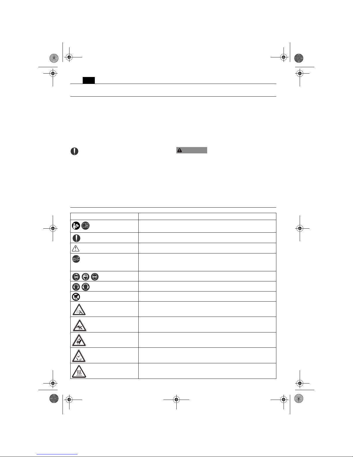
Symbols.
WARNING
Symbol, character Explanation
Make sure to read the enclosed documents such as the
Instruction Manual and the General Safety Instructions.
Observe the instructions in the text or graphic opposite!
Observe the instructions in the text or graphic opposite!
Before commencing this working step, pull the power plug
out of the socket. Otherwise there will be danger of injury if
the power tool should start unintentionally.
Use eye protection during operation.
Use ear protection during operation.
Do not touch the rotating parts of the power tool.
Warning against sharp edges of application tools, such as the
cutting edges of the cutter blades.
Danger of slipping!
Danger of crushes or contusions!
Caution! Falling objects!
Hot surface!
OBJ_BUCH-0000000261-003.book Page 8 Thursday, January 11, 2018 5:30 PM
9
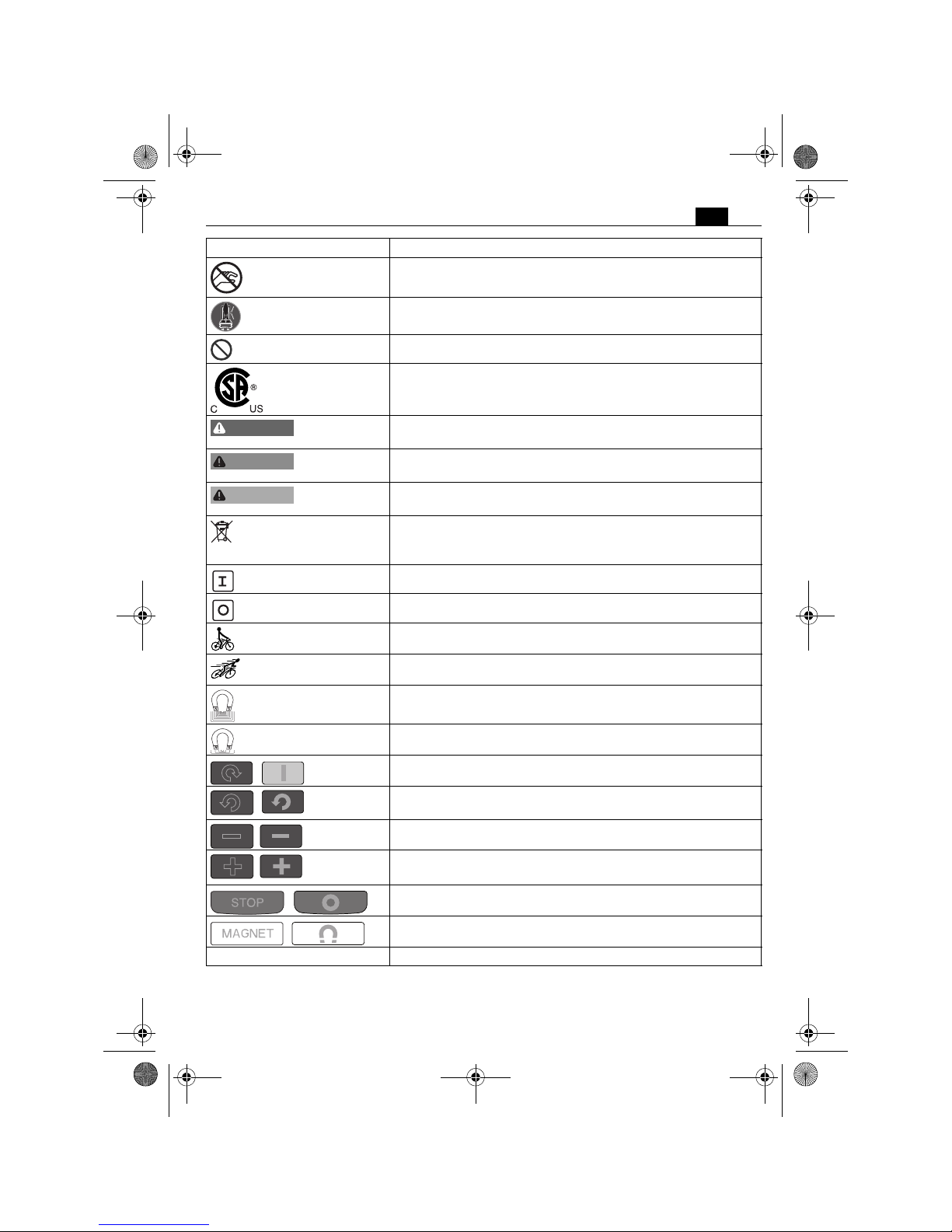
en
Do not reach in!
Fasten strap!
General prohibition sign. This action is prohibited.
This symbol confirms the certification of this product for the
USA and Canada.
This sign warns of a directly imminent, dangerous situation. A
false reaction can cause a severe or fatal injury.
This sign indicates a possible dangerous situation that could
cause severe or fatal injury.
This sign warns of a possible dangerous situation that could
cause injury.
Worn out power tools and other electrotechnical and electrical products should be sorted separately for environmentallyfriendly recycling.
Start drill motor. Rotation direction: clockwise
Stop motor
Low speed
High speed
Magnetic holding power, sufficient
Magnetic holding power, insufficient
Start drill motor. Rotation direction: clockwise
Start drill motor in inch mode. Rotation direction: counterclockwise
Speed reduction in steps
Speed increase in steps
Stop motor
Switches the magnet On/Off
(**) may contain numbers and letters
Symbol, character Explanation
DANGER
WARNING
CAUTION
OBJ_BUCH-0000000261-003.book Page 9 Thursday, January 11, 2018 5:30 PM
10
en
Character Unit of measurement,
national
Explanation
n
0
rpm; /min; min-1; r/min No-load speed
P
W Electrical power
°Angle width
U V Electric voltage
f Hz Frequency
I
A Electric current intensity
m
lbs Mass
l ft, in Length, width, height, depth, diameter or thread
Ø ft, in Diameter of a round part
m, s, kg, A, mm, V, W,
Hz, N, °C, dB, min, m/s
2
Basic and derived units of measurement from the
international system of units SI.
OBJ_BUCH-0000000261-003.book Page 10 Thursday, January 11, 2018 5:30 PM
11
en
Technical description and specifications.
Before mounting or replacing cutting tool or accessories, pull the power plug.
This preventive safety measure rules out the danger of injuries through accidental starting of the power tool.
Not all accessories described or shown in this instruction manual will be included with yourpower tool.
WARNING
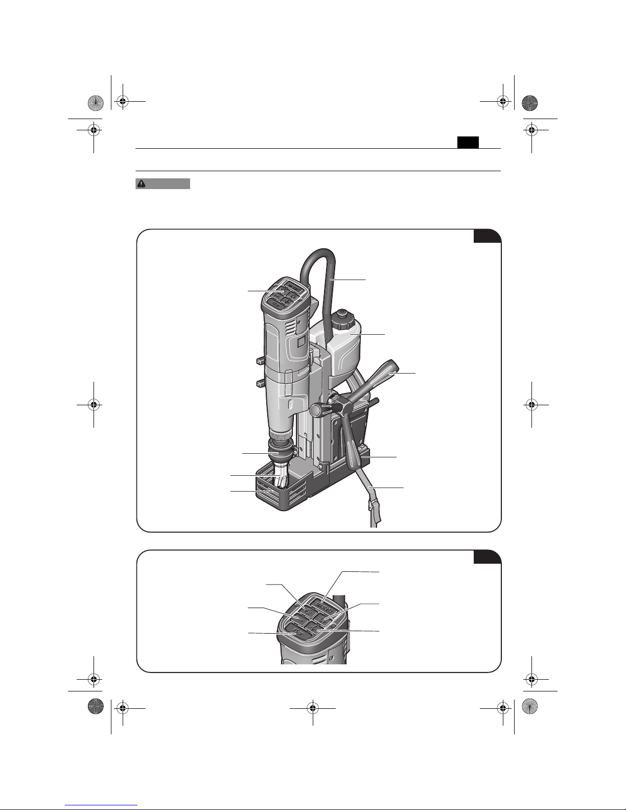
Application tool
Chip guard
Tool holder
Viseo Touch Pad
Drill-motor cable
Coolant container
Spoke handle
Magnetic foot
Clamping strap
Fig. 1
Switches the magnet On/Off
Starts the drill motor
Rotation direction: clockwise
Speed reduction in steps
Starts the drill motor in inch mode
Rotation direction: anticlockwise
Stops the drill motor
Speed increase in steps
Fig. 2
OBJ_BUCH-0000000261-003.book Page 11 Thursday, January 11, 2018 5:30 PM
12
en
Type JMU 137 QW (**) JMU 137 MQW (**) JMU 137-2 QW (**)
Order number 7 270 ... 7 270 ... 7 270 ...
Current consumption 9.2 A 9.2 A 9.2 A
No-load speed (right rotation)
1. Gear 550 /min 550 /min 550 /min
2. Gear – – 1700 /min
No-load speed (left rotation)
1. Gear 370 /min 370 /min 370 /min
2. Gear – – 1140 /min
Drilling capacity in steel - TCT/
high speed steel (core drill bits)
7/16 in – 1 3/8 in
11 mm – 35 mm
7/16 in – 1 3/8 in
11 mm – 35 mm
7/16 in – 1 3/8 in
11 mm – 35 mm
Drilling capacity in steel - high
speed steel (HSS) (twist drill bit)
5/8 in
16 mm
11/16 in
18 mm
5/8 in
16 mm
Tapped hole 9 16/4 in
M14
9 16/4 in
M14
9 16/4 in
M14
Reamer diameter 5/8 in
16 mm
11/16 in
18 mm
5/8 in
16 mm
Counterboring diameter 1 1/4 in
32 mm
1 1/4 in
32 mm
1 1/4 in
32 mm
Weight according to
EPTA-Procedure 01
23.4 lbs
(10.6 kg)
24.25 lbs
(11.0 kg)
24.25 lbs
(11.0 kg)
Class of protection /I /I /I
Allowable ambient temperature 23°F ... 104°F
–5°C ... +40° C
23°F ... 104°F
–5°C ... +40°C
23°F ... 104°F
–5°C ... +40°C
OBJ_BUCH-0000000261-003.book Page 12 Thursday, January 11, 2018 5:30 PM
13
en
Assembly instructions.
Before mounting or replacing cutting tool or accessories, pull the power plug.
This preventive safety measure rules out the danger of injuries through accidental starting of the power tool.
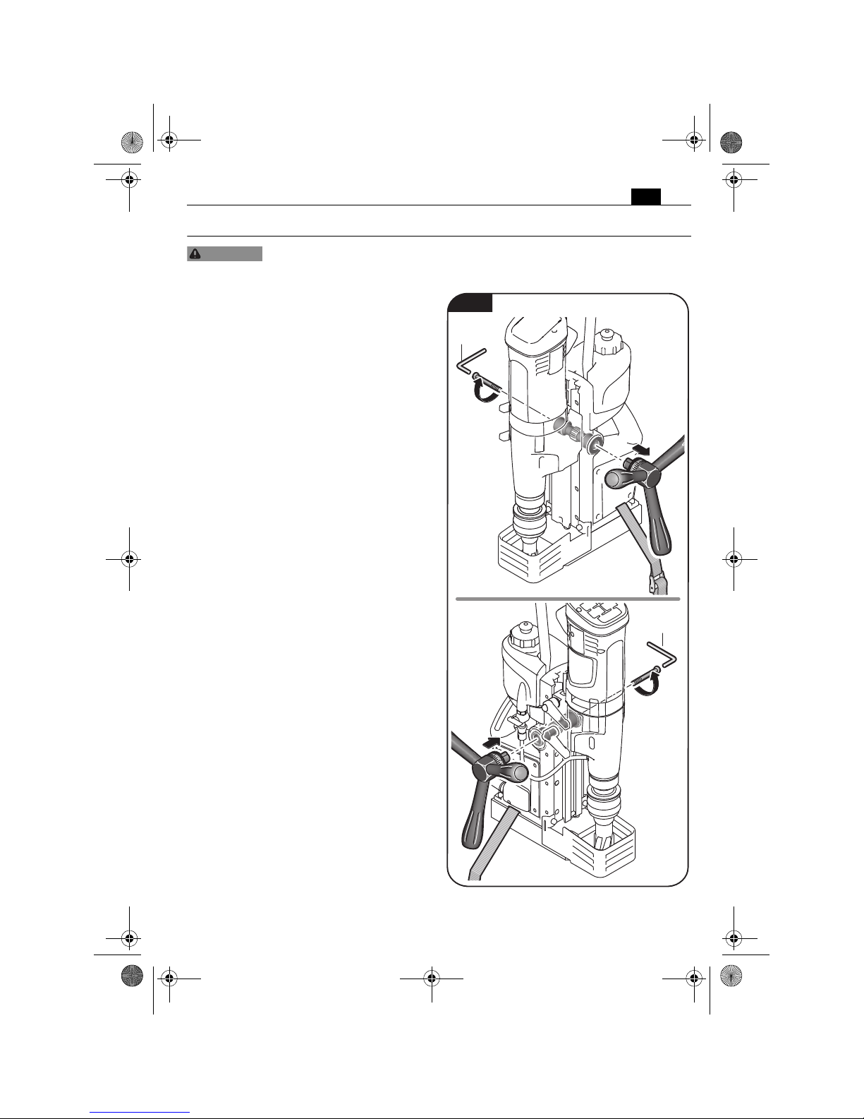
Mounting the spoke handle
(figure 3).
The hub assembly can be mounted on either
side.
Loosen the screw using a hex key.
Remove the spoke handle.
Mount the spoke handle on the other side
and tighten the screw using a hex key.
WARNING
1.
2.
3.
4.
5 mm /
3/16 in
5 mm /
3/16 in
Fig. 3
OBJ_BUCH-0000000261-003.book Page 13 Thursday, January 11, 2018 5:30 PM
14
en
Filling the coolant container.
Prevent the flow of liquid along the cable into the socket outlet or into the core
drill unit, as this can lead to electric shock. Tie a bow in the cable near the plug,
so that any liquid can drip off.
Do not use the magnetic core drill unit when the cooling-lubricant system is defective. Each
time before operating, check for tightness against leaks and for cracks in the hoses. Prevent liquids from entering or penetrating electrical components.
Only use a coolant-lubricant emulsion (oil in water) as the cooling agent.
Observe the manufacturer's instructions on coolant.
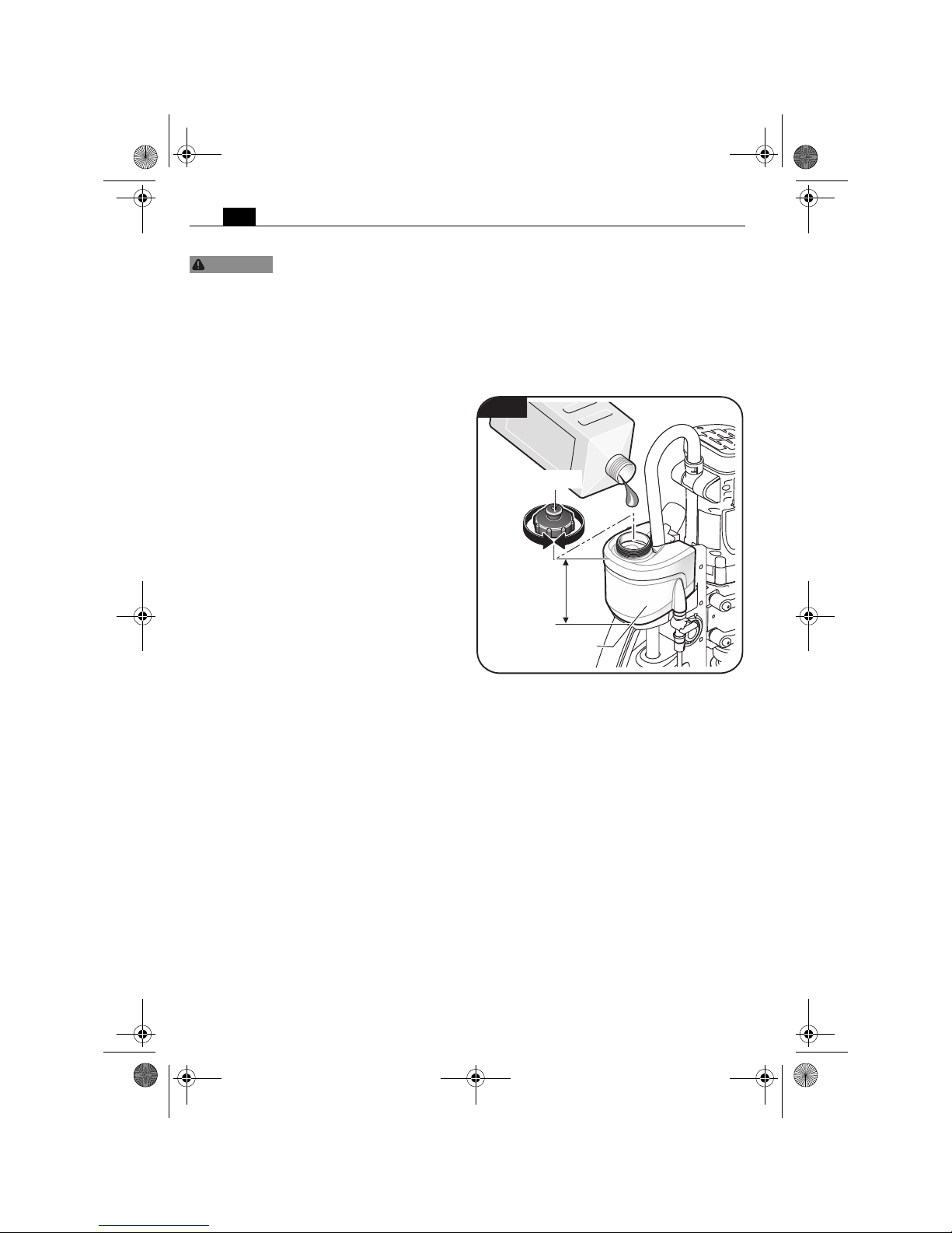
Filling the mounted coolant container
(figure 4)
Unscrew the cap from the coolant container.
Fill in pump-feedable cooling lubricant,
e.g. Slugger cutting oil.
Screw the cap onto the coolant container
again.
WARNING
3.
1.
2.
Coolant container
Upper closing cap
max. 500 ml
max. 17 fl. OZ.
Fig. 4
OBJ_BUCH-0000000261-003.book Page 14 Thursday, January 11, 2018 5:30 PM
15
en
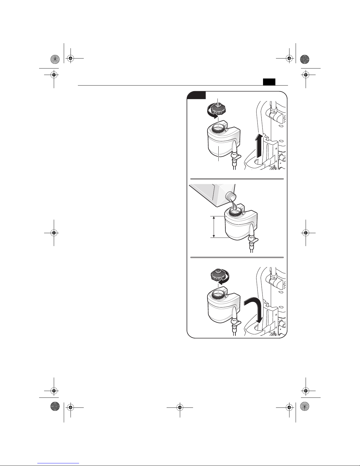
Filling the dismounted coolant container
(figure 5)
Pull the empty coolant container out of the
drill stand housing of the magnetic core drill.
Unscrew the cap from the coolant container.
Fill in pump-feedable cooling lubricant,
e.g. Slugger cutting oil.
Screw the cap onto the coolant container
again.
Insert the filled coolant container into the
holder on the drill stand housing intended for
this purpose.
1.
3.
2.
5.
4.
Coolant container
Upper closing cap
max. 500 ml
max. 17 fl. OZ.
Fig. 5
OBJ_BUCH-0000000261-003.book Page 15 Thursday, January 11, 2018 5:30 PM
16
en
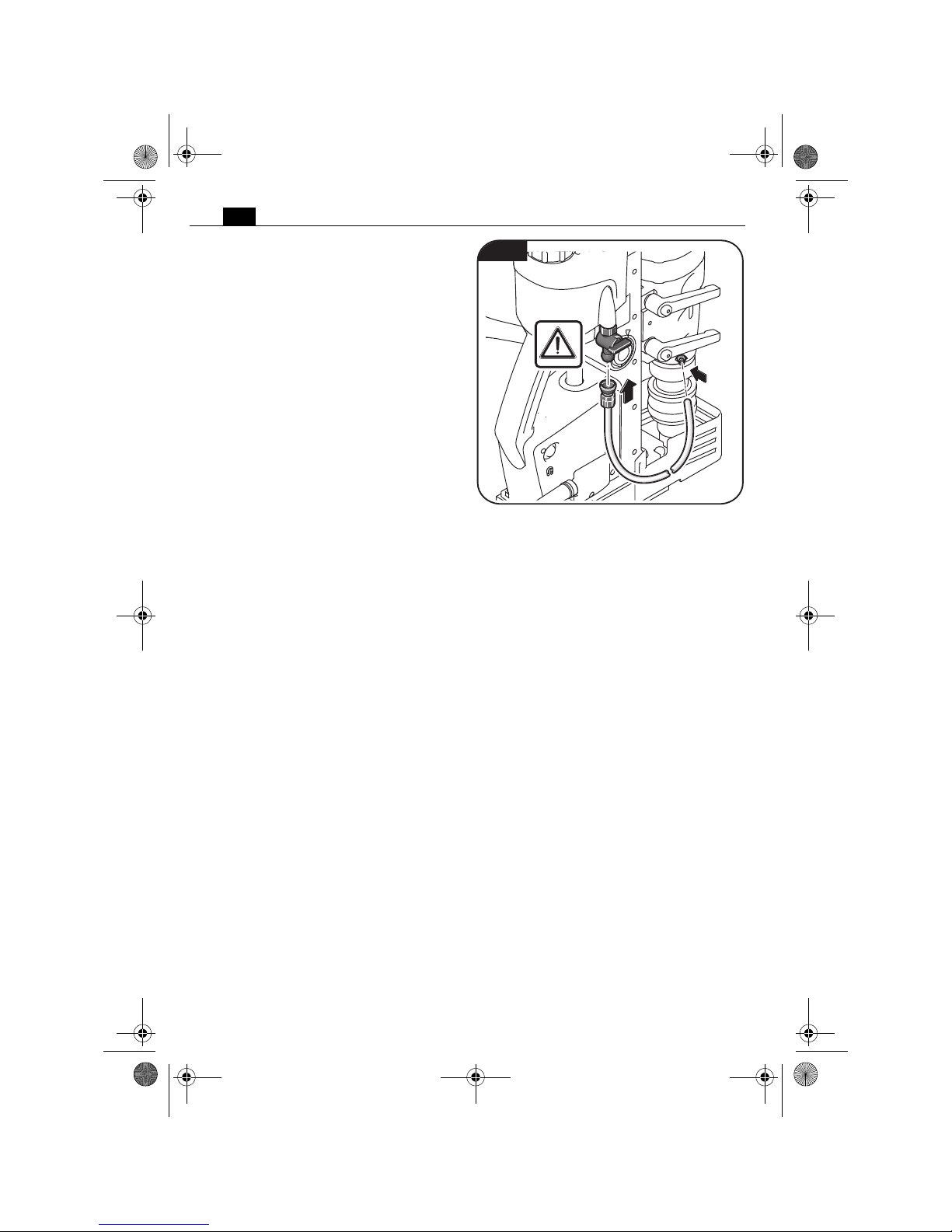
Mounting the coolant hose (figure 6).
Connect the coolant hose.
Fig. 6
OBJ_BUCH-0000000261-003.book Page 16 Thursday, January 11, 2018 5:30 PM
17
en
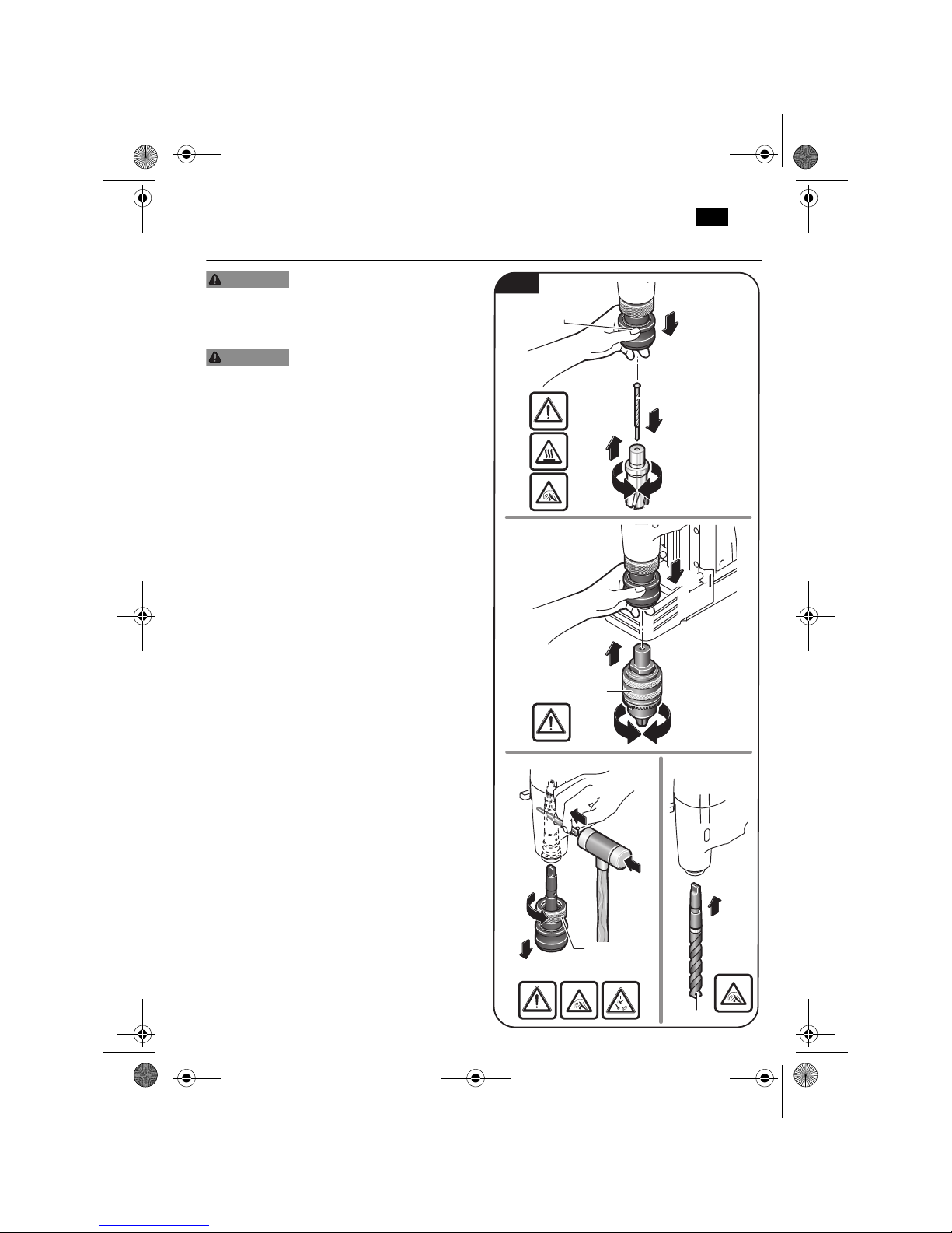
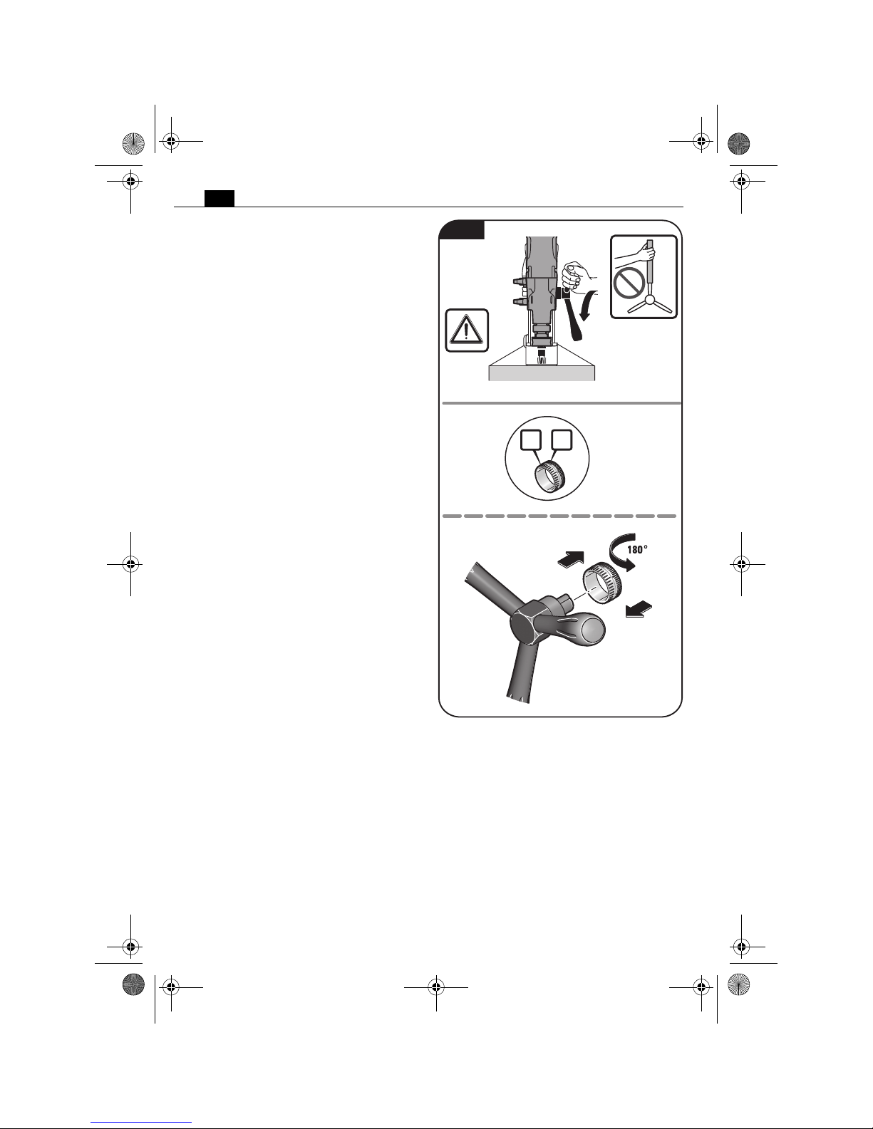
Tool changing (figure 7).
Always secure the power tool
with the supplied clamping
strap. In case of a power failure or when the
power plug is pulled, the magnetic holding
power is not maintained.
Switch the machine off and
pull the power plug before
mounting or replacing application tools and
accessories (not overhead!). This preventive
safety measure rules out the danger of injuries
through accidental starting of the power tool.
Core drill bit
Insert the pilot pin into the cutter.
Pull the clamping sleeve of the tool holder
down and insert the core drill bit with the
centering pin into the tool holder.
Do not touch the sharp edges of the core drill
bit. Danger of injury.
Drill chuck
Pull the clamping sleeve of the tool holder
down and insert the drill chuck.
Drill bit
The knurled nut has a left-hand thread; turn
clockwise to release!
Loosen the knurled nut and remove the tool
holder by applying a hammer blow to the
positioned drift.
Clean the inside cone of the output shaft and
insert the drill bit.
WARNING
WARNING
1.
2.
3.
2.
3.
4.
1.
Drill chuck
Clamping sleeve
Centering pin
Core drill bit
JMU 137 MQW
1.
3.
2.
4.
5.
MK 2
MT 2
CM 2
Drill bit
Knurled nut
Fig. 7
OBJ_BUCH-0000000261-003.book Page 17 Thursday, January 11, 2018 5:30 PM
18
en
Working instructions.
Always secure the power tool with the supplied clamping strap. In case of a
power failure or when the power plug is pulled, the magnetic holding power is
not maintained.
Always carry the power tool by its handle, not by the drill-motor cable.
Fastening the safety strap (figure 9).
Always secure the power tool to the workpiece with the supplied clamping strap.
WARNING
Fig. 8
Clamping strap
Fig. 9
OBJ_BUCH-0000000261-003.book Page 18 Thursday, January 11, 2018 5:30 PM
19
en
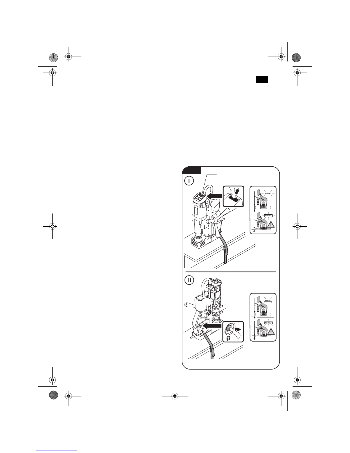
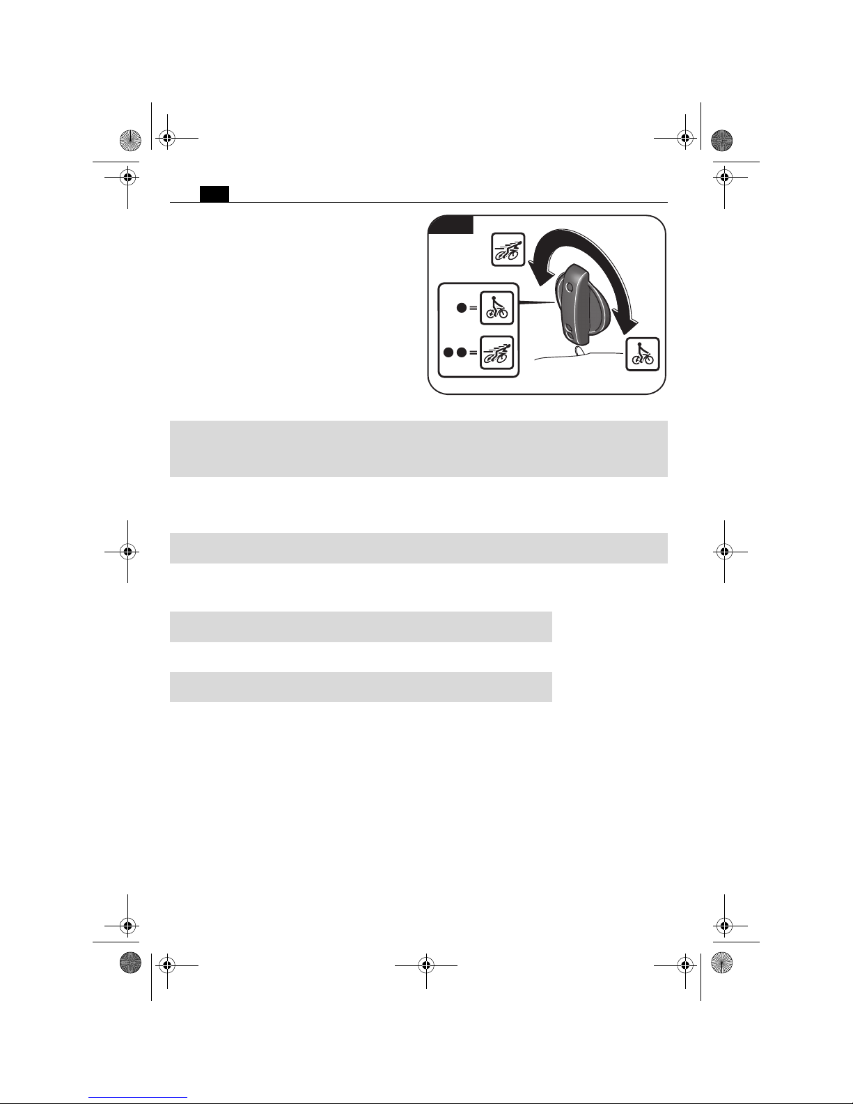
For switching the magnet ON
(figure 10).
Pay attention that the set-up surface for the
magnetic foot is flat, clean, rust-free and icefree. Remove varnish, putty/filler layers and
other materials. Prevent an air gap between
the magnetic foot and the set-up surface. The
air gap reduces the magnetic holding power.
When working, always use the magnetic foot;
pay attention that the magnetic holding
power is sufficient:
– When the green button on the control
panel lights up permanently, the magnetic
holding power is sufficient and the machine
can be operated with normal feed.
– When the Magnet button on the control
panel flashes, the magnetic holding power
possibly is insufficient and the machine
must be operated with reduced feed.
When working on materials that are non-ferrous, suitable fixation devices obtainable as
accessories from the manufacturer, e. g. suction plates, vacuum plates or pipe-drilling
devices must be used.
When working on steel materials with a
material thickness of less than 12 mm /
1
/2in,
the workpiece must be reinforced with an
additional steel plate in order to guarantee the
magnetic holding power.
Work only with the absolutely required
amount of feed. Excessive feed can lead to
breakage of the application tool and loss of
the magnetic holding power.
The magnetic foot is monitored by means of
a power sensor. If the magnetic foot is defective, the motor will not start.
When the power supply is disconnected
while the motor is running, a protective circuit prevents automatic restarting of the
motor. Restart the motor again. Adjust the
gear setting only when the machine is at a
complete stop or when the motor is running
down. Do not stop the drill motor during the
drilling procedure. Remove the core drill bit
from the drill hole only while the drill motor
is running. If the core drill bit gets jammed/
stuck in the material, stop the drill motor and
carefully rotate out the core drill bit turning in
counterclockwise direction. After each drilling run, remove the chips and the drilled out
core. Do not touch the chips with your bare
hands. Always use a chip hook. Danger of
burning! The surface of the magnet can reach
high temperatures. Do not touch the magnet
with your bare hands. When changing a drill
bit, pay attention not to damage the cutting
edges. When core-drilling layered material,
remove the core and the chips after having
drilled through each layer. Do not use the
magnetic core drill unit when the coolinglubricant system is defective. Check for tightness against leaks and for cracks in the hoses.
Prevent liquids from entering or penetrating
electrical components. The core drill units do
not have overload protection. In case of
improper use, the motor can become damaged.
=
Switches the magnet On/Off
=
Switches the magnet On/Off
Fig. 10
> 12 mm
< 12 mm
> 12 mm
< 12 mm
OBJ_BUCH-0000000261-003.book Page 19 Thursday, January 11, 2018 5:30 PM
20
en
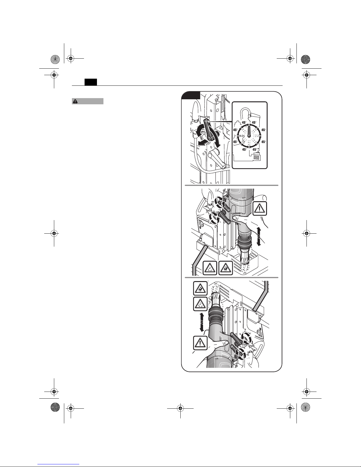
Adjusting the stroke range (figure 11).
Hold the power tool firmly
with one hand when releasing
the two fastening levers.
To move the fastening levers over each other,
pull a fastening lever outward and then turn
the fastening lever in 45° steps.
Loosen both fastening levers with the other
hand.
Adjust the desired stroke range.
Tighten both fastening levers again.
CAUTION
1.
2.
2.
3.
1.
4.
4.
2.
2.
1.
3.
4.
4.
2.
2.
Fig. 11
OBJ_BUCH-0000000261-003.book Page 20 Thursday, January 11, 2018 5:30 PM
21
en
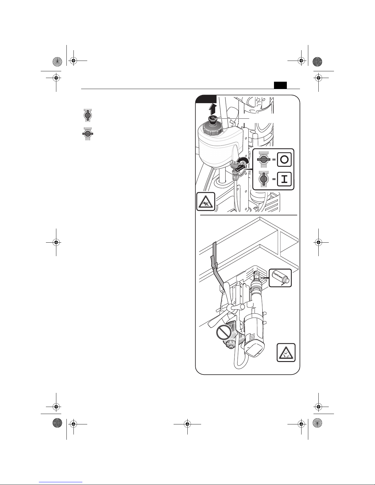
Activating and deactivating the coolant-lubricant flow (figure 12).
To activate the cooling-lubricant flow,
open the ventilation first and then turn
the flow valve to the position shown.
For switching off or when working
overhead, deactivate the cooling-lubricant flow. Shut the ventilation and turn
the flow valve to the position shown.
When working overhead, use a cooling-lubricant paste from Slugger.
1.
2.
Ventilation
Fig. 12
OBJ_BUCH-0000000261-003.book Page 21 Thursday, January 11, 2018 5:30 PM
22
en
Switching the gear setting (figure 13).
With the gear switch, you can select the
speed and thus the torque.
Adjust the gear setting only when the
machine is at a complete stop or when the
motor is running down.
Set the switch to gear 1 to work at low speed
with high torque. This setting is suitable for
drilling with large drill bit diameters and for
tapping.
Set the switch to gear 2 to work a t high speed
with low torque. This setting is suitable for
drilling with small drill bit diameters.
Fig. 13
Drilling capacity
in steel - TCT/
high speed steel
(core drill bits)
Drilling capacity
in steel - high speed
steel (HSS)
(twist drill bit)
Tapped hole
JMU 137 QW
(**),
JMU 137-2 QW
(**)
1. Gear 7/16 in – 1 3/8 in
11 mm – 35 mm
1/4 in – 5 8/8 in
6 mm – 16 mm
3/8 in – 9/16 in
M5 – M14
JMU 137 MQW
(**)
1. Gear 7/16 in – 1 3/8 in
11 mm – 35 mm
3/8 in – 11 16/8 in
10 mm – 18 mm
3/8 in – 9/16 in
M5 – M14
JMU 137-2QW
(**)
2. Gear
–
1/16 in – 3 8/8 in
1.5 mm – 9 mm
-
Max. diameter
for reaming
Max. diameter for
counterboring
JMU 137 MQW
(**)
1. Gear ≤ 5/8 in
≤ 16 mm
≤ 1 1/4 in
≤ 32 mm
JMU 137 MQW
(**)
1. Gear ≤ 11/16 in
≤ 18 mm
≤ 1 1/4 in
≤ 32 mm
JMU 137-2QW
(**)
1. Gear ≤ 5/8 in
≤ 16 mm
≤ 1 1/4 in
≤ 32 mm
OBJ_BUCH-0000000261-003.book Page 22 Thursday, January 11, 2018 5:30 PM
23
en
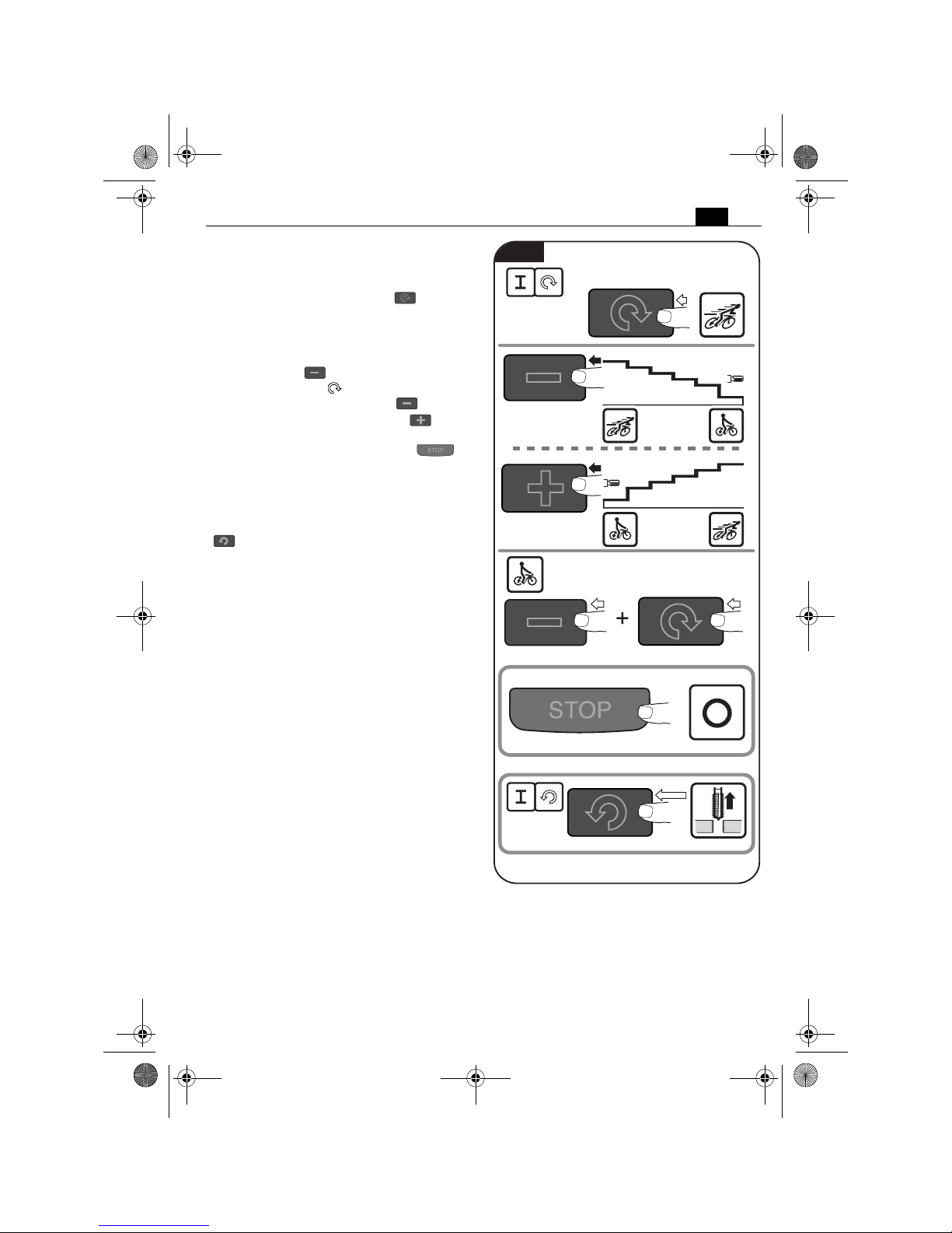
Starting and stopping the drill motor
(figure 14).
To start the drill motor with clockwise rotation, press the button with the „ “ symbol.
The drill motor starts with the highest speed.
The last set speed is automatically stored
(Memory Function). To start the power tool
with the last set speed, press and hold the
button with the symbol, and then press
the button with the symbol.
To lower the speed, press the „ “ symbol.
To increase the speed, press the „ “ symbol.
To stop the drill motor, press the „ “
symbol.
Do not stop the drill motor during the drilling
procedure.
To start the drill motor with counterclockwise rotation, press the button with the
„ “ symbol. The drill motor will run as
long as the button is pressed.
When the power supply is disconnected
while the drill motor is running (e.g. removal
of the battery), a protective circuit prevents
automatic restarting of the drill motor. Restart
the drill motor again.
In case of overload, the drill motor automatically stops and must be restarted again.
100l%
85
l%
75
l%
60
l%
50
l%
25
l%
100
l%
85
l%
75
l%
60
l%
50
l%
25
l%
Memory Function
Fig. 14
OBJ_BUCH-0000000261-003.book Page 23 Thursday, January 11, 2018 5:30 PM
24
en
Feed (figure 15).
Work only with the absolutely required
amount of feed. Excessive feed can lead to
breakage of the application tool and loss of
the magnetic holding power.
To generate feed, turn the spoke handle manually while the drill motor is switched on.
The scale can be used with “inch” or with
“cm” graduation.
cm
inch
1.
inch
cm
3.
2.
Fig. 15
OBJ_BUCH-0000000261-003.book Page 24 Thursday, January 11, 2018 5:30 PM

25
en
Instructions for core drilling.
Only remove the cutting tool from the hole
while the motor is running.
If the carbide tipped cutter should remain
stuck in the material, stop the drill motor and
carefully turn the carbide tipped cutter out
counterclockwise.
After each drilling operation, remove the
chips and the slug.
Do not touch the chips with your bare
hand. Always use a chip hook.
Danger of burns! The surface
of the magnet can reach high
temperatures. Do not touch the magnet with
your bare hands.
For core drilling in layered material, use a suitable Slugger ID cutter.
When changing a cutting tool, pay attention
not to damage the cutting edges.
When core drilling layered material, remove
the core and the chips after having drilled
through each layer.
CAUTION
Error message/
Response of magnet
button
Meaning Corrective action
Indicator lights up
green
Magnetic holding power is
sufficient.
Indicator flashes
green
Magnetic holding power
possibly insufficient.
Even when working on steel materials where the material thickness is
below 12 mm, the workpiece must
be made thicker with an additional
steel plate in order to ensure the
magnetic holding power.
Indicator lights up red
for 1 second
– Motion sensor has actuated
– Overload shut-off has
actuated
– Incorrect mains voltage
After malfunction correction, the
power tool can be switched on again.
Indicator flashes red
3 x
No speed signal If the error occurs frequently, send
the machine to your Slugger customer service agent.
Indicator lights up red
continuously
– Incorrect mains voltage/
mains frequency
– Drill stand is overheated
– Button is blocked when
switching on
After malfunction correction, the
power tool can be switched on again.
If the error occurs frequently, send
the machine to your Slugger customer service agent.
Indicator flashes red
continuously
Power tool is defective. Send the machine to your Slugger
customer service agent
OBJ_BUCH-0000000261-003.book Page 25 Thursday, January 11, 2018 5:30 PM

26
en
Repair and customer service.
Before mounting or replacing cutting tool or accessories, pull the power plug.
This preventive safety measure rules out the danger of injuries through accidental starting of the power tool.
Exchangeable parts
If required, you can change the following
parts yourself:
application tools, coolant container
Drill-motor guide (figure 16).
After several hours of operation, the play in the drill-motor guide can increase. As a consequence, the drill motor can glide alongside the drill-motor guide by itself. Malfunctions are possible in machine operation. In this case, retighten all fastening screws of the drill-motor guide
correspondingly so that the drill motor can easily be moved manually, yet does not glide by
itself.
WARNING
2,5 mm /
3/32 in
2,5 mm /
3/32 in
2,5 mm /
3/32 in
Fig. 16
OBJ_BUCH-0000000261-003.book Page 26 Thursday, January 11, 2018 5:30 PM

27
en
Service.
Have maintenance carried out
only through qualified personnel. Incorrectly mounted cables and components can cause serious injuries. Have the
required service carried out only through an
authorized Slugger repair facility.
When replacing the power
tool's protective cable bushing
or cord between the drill stand and drill
motor is required, this must be carried out by
Slugger or by an authorized Slugger Service
Agent, in order to avoid hazardous situations.
Use only original spare parts.
The current spare parts list for this power
tool can be found in the Internet at
www.fein.com.
Cleaning.
Prior to any cleaning or main-
tenance, disconnect the power
tool from the power supply in order to avoid
accidents.
When using in environments
with conductive dust in the air,
such as when working metals, this dust can
settle in the interior of the power tool. This
can impair the total insulation of the power
tool. Therefore, regularly blow out the interior
of the power tool from outside via the ventilation openings with dry, oil-free compressed
air; always wear eye protection when doing
this. For additional protection, connect a
residual current device (RCD) on the line side.
Do not attempt to clean
clogged or dirty ventilation
openings of the power tool with pointed
metal objects; use nonmetal tools or objects
if necessary.
Do not use cleaning agents
and solvents that can cause
damage to plastic parts. These include: Gas-
oline, carbon tetrachloride, chloric solvents,
ammonia and domestic cleaning agents that
contain ammonia.
Cooling-lubricant system.
Flush the cooling-lubricant system with
water, clean and drain it completely when not
using the machine for periods longer than
two weeks.
Warranty and liability.
The warranty for the product is valid in accordance with the legal regulations in the country
where it is marketed.
Environmental protection, disposal.
Sort scrapped power tools and accessories for environmental-friendly recycling. For further
information, please contact your specialist shop.
WARNING
CAUTION
WARNING
WARNING
CAUTION
CAUTION
OBJ_BUCH-0000000261-003.book Page 27 Thursday, January 11, 2018 5:30 PM

28
en
Provided accessories (figure 17).
Drift
Power tool carrying case
Chip hook
Centering pin
Clamping strap
Chip guard
Tool holder
105 mm
JMU 137 MQW (**)
JMU 137 MQW (**)
Fig. 17
OBJ_BUCH-0000000261-003.book Page 28 Thursday, January 11, 2018 5:30 PM

29
fr
fr
Pour votre sécurité.
Lire tous les avertissements de sécurité et
toutes les instructions. Ne pas suivre les aver-
tissements et instructions peut donner lieu à
une électrocution, un incendie et/ou une
blessure sérieuse.
Conservez tous les avertissements et toutes
les instructions pour pouvoir vous y reporter
ultérieurement.
Ne pas utiliser cet outil électrique avant
d’avoir soigneusement lu et parfaitement
compris cette notice d’utilisation y compris
les figures, les spécifications, les consignes de
sécurité ainsi que les indications marquées par
DANGER, AVERTISSEMENT et ATTENTION.
N’utiliser cet outil électrique que pour les travaux pour lesquels il a été conçu par le fabricant. N’utiliser que des outils de travail et
accessoires autorisés par le fabricant.
De même, respecter les dispositions concernant la prévention des accidents du travail en
vigueur dans le pays en question.
Le non-respect des instructions de sécurité se
trouvant dans la documentation mentionnée
peut entraîner un choc électrique, un incendie
et / ou de graves blessures.
Bien garder cette notice d’utilisation en vue
d’une utilisation ultérieure ; elle doit être
jointe à l’appareil en cas de transmission ou de
vente à une tierce personne.
GARDER SOIGNEUSEMENT CES INSTRUCTIONS DE SECURITE.
Le terme « outil électrique » dans les consignes de sécurité fait référence à votre outil
électrique alimenté par le secteur (avec cordon d’alimentation) ou votre outil fonctionnant sur batterie (sans cordon
d’alimentation).
Instructions générales de
sécurité.
1) Portée
a)Maintenir la zone de travail propre et
bien éclairée. Les zones en désordre ou
sombres sont propices aux accidents.
b)Ne pas faire fonctionner les outils élec-
trique en atmosphère explosive, par
exemple en présence de liquides inflammables, de gaz ou de poussières. Les
outils électroportatifs produisent des
étincelles qui peuvent enflammer les
poussières ou les fumées.
c) Maintenir les enfants et les personnes
présentes à l’écart pendant l’utilisation
de l’outil. Les distractions peuvent vous
faire perdre le contrôle de l’outil.
2) Sécurité électrique
a) Il faut que les fiches de l’outil électrique
soient adaptées au socle. Ne jamais
modifier la fiche de quelque façon que
ce soit. Ne pas utiliser d’adaptateurs
avec des outils à branchement de terre.
Des fiches non modifiées et des socles
adaptés réduiront le risque de choc
électrique.
b)Éviter tout contact du corps avec des
surfaces reliées à la terre telles que
tuyaux, radiateurs, cuisinières et réfrigérateurs. Il existe un risque accru de
choc électrique si votre corps est relié à
la terre.
c) Ne pas exposer les outils à la pluie ou à
des conditions humides. La pénétration
d’eau à l’intérieur d’un outil augmentera
le risque de choc électrique.
d)Veiller à ne pas endommager le cordon.
Ne jamais utiliser le cordon pour porter,
tirer ou débrancher l’outil. Maintenir le
cordon à l’écart de toute source de chaleur, de lubrifiant, d’arêtes ou de parties
en mouvement. Des cordons endomma-
gés ou emmêlés augmentent le risque
de choc électrique.
e) Lors qu’on utilise un outil à l’extérieur,
utiliser un prolongateur adapté à l’utilisation extérieure. L’utilisation d’un cor-
don adapté à un usage à l’extérieur
réduit le risque de choc électrique.
f) Si l’usage d’un outil dans un emplace-
ment humide est inévitable, utilisez une
alimentation protégée par un dispositif
à courant différentiel résiduel (RCD).
L’usage d’un RCD réduit le risque de
choc électrique.
AVERTISSEMENT
OBJ_BUCH-0000000261-003.book Page 29 Thursday, January 11, 2018 5:30 PM

30
fr
3) Sécurité des personnes
a)Rester vigilant, regarder ce que vous
êtes en train de faire. Faire preuve de
bon sens lors de l’utilisation de l’outil.
Ne pas utiliser un outil lorsque vous êtes
fatigué ou sous l’emprise de drogues,
d’alcool ou de médicaments. Un
moment d’inattention en cours d’utilisation d’un outil peut entraîner des graves
blessures.
b)Utiliser un équipement de sécurité. Tou-
jours porter une protection pour les
yeux. Les équipements de sécurité tels
que les masques contre les poussières,
les chaussures de sécurité antidérapantes, les casques ou les protections
acoustiques utilisés pour les conditions
appropriées réduiront les blessures de
personnes.
c) Eviter tout démarrage intempestif.
S’assurer que l’interrupteur est en position arrêt avant de retirer la fiche de la
prise de courant. Porter les outils en
ayant le doigt sur l’interrupteur ou brancher des outils dont l’interrupteur est en
position marche est source d’accidents.
d)Retirer toute clé de réglage avant de
mettre l’outil en marche. Une clé laissée
fixée sur une partie tournante de l’outil
peut provoquer des blessures.
e) Ne pas se précipiter. Garder une posi-
tion et un équilibre adaptés à tout
moment. Cela permet un meilleur
contrôle de l’outil dans des situations
inattendues.
f) S’habiller de manière adaptée. Ne pas
porter de vêtements amples ou de
bijoux. Garder les cheveux, les vêtements et les gants à distance des parties en mouvement. Des vêtements
amples, des bijoux ou les cheveux longs
peuvent être pris dans des parties en
mouvement.
g)Si des dispositifs sont fournis pour le
raccordement d’équipements pour
l’extraction et la récupération des poussières, s’assurer qu’ils sont connectés
et correctement utilisés. Utiliser des
collecteurs de poussière peut réduire
les risques dus aux poussières.
4) Utilisation et entretien de l’outil
a)Ne pas forcer l’outil. Utiliser l’outil
adapté à votre application. L’outil adap-
té réalisera mieux le travail et de manière plus sûre au régime pour lequel il a
été construit.
b)Ne pas utiliser l’outil si l’interrupteur ne
permet pas de passer de l’état de marche à l’état d’arrêt et vice versa. Tout
outil qui ne peut pas être commandé par
l’interrupteur est dangereux et il faut le
réparer.
c) Débrancher la fiche de la source d’ali-
mentation en courant et/ou le bloc de
batteries de l’outil avant tout réglage,
changement d’accessoires ou avant de
ranger l’outil. De telles mesures de
sécurité préventives réduisent le risque
de démarrage accidentel de l’outil.
d)Conserver les outils à l’arrêt hors de la
portée des enfants et ne pas permettre
à des personnes ne connaissant pas
l’outil ou les présentes instructions de le
faire fonctionner. Les outils sont dange-
reux entre les mains d’utilisateurs novices.
e) Veiller à la maintenance de l’outil.
S’assurer qu’il n’y a pas de mauvais alignement ou de blocage des parties
mobiles, des pièces cassées ou toute
autre condition pouvant affecter le fonctionnement de l’outil. En cas de dommages, faire réparer l’outil avant de
l’utiliser. De nombreux accidents sont
dus à des outils mal entretenus.
f) Garder affûtés et propres les outils per-
mettant de couper. Des outils destinés à
couper correctement entretenus avec
des pièces coupantes tranchantes sont
moins susceptibles de bloquer et sont
plus faciles à contrôler.
g)Utiliser l’outil, les accessoires et les
lames etc., conformément à ces instructions et aux prescriptions en vigueur
pour ce type d’appareil. Tenir compte
également des conditions de travail et
du travail à réaliser. L’utilisation de
l’outil pour des opérations différentes
de celles prévues pourrait donner lieu à
des situations dangereuses.
OBJ_BUCH-0000000261-003.book Page 30 Thursday, January 11, 2018 5:30 PM

31
fr
5) Maintenance et entretien
a)Faites entretenir l’outil par un répara-
teur qualifié utilisant uniquement des
pièces de rechange identiques. Cela
assurera que la sécurité de l’outil soit
maintenue.
Instructions particulières de sécurité.
Toujours porter un équipement de protection.
En fonction de l’application, porter un écran
facial ou des lunettes de sécurité. Utiliser une
protection auditive. Les lunettes de sécurité
doivent pouvoir protéger les yeux contre les
particules projetées lors de toutes sortes de
travaux. Une exposition permanente au bruit
intense peut provoquer une perte de l’audition.
Ne pas toucher les bords aigus de la fraise à
carotter. Danger de blessure.
Remplacer immédiatement une gaine de protection endommagée. Une gaine de protec-
tion défectueuse peut entraîner une
surchauffe de la machine et avoir un arrêt
d’urgence pour conséquence.
Avant la première mise en service : Monter le
protège-mains sur la machine.
Sécuriser l’outil électrique uniquement avec
la sangle livrée avec. La force d’attraction
magnétique n’est plus active lors d’une panne
de courant ou lorsque l’appareil est débranché. Lors des travaux, veiller à toujours se
protéger contre les objets tombants tels que
carottes et copeaux.
Effectuez les travaux sur les éléments de
construction verticaux ou au-dessus de la tête
sans utiliser le réservoir du liquide de refroidissement. Utilisez un spray refroidissant. Les
liquides qui entreraient dans l’outil électrique
peuvent causer un choc électrique.
Évitez de toucher la carotte qui est automatiquement éjectée par la goupille de centrage
quand le travail est terminé. Le contact avec
la carotte brûlante ou qui tombe peut entraîner des blessures.
N’utilisez l’outil électrique qu’avec des prises
de courant de sécurité conformes à la législation. N’utilisez que des câbles de raccordement en parfait état et des rallonges
régulièrement contrôlées. Un conducteur de
protection discontinu peut entraîner un choc
électrique.
Maintenir vos mains, vêtements etc. toujours
loin des copeaux en rotation pour éviter de
vous blesser. Les copeaux peuvent causer des
blessures. Toujours utiliser le protège-mains.
N’essayez pas d’enlever l’outil de travail tant
qu’il est en rotation. Ceci peut causer de gra-
ves blessures.
Tenir l’outil par les surfaces de préhension
isolées, lors de la réalisation d’une opération
au cours de laquelle l’organe de coupe peut
entrer en contact avec un câblage non apparent ou son propre cordon d’alimentation. Le
contact avec un fil « sous tension » peut également mettre « sous tension » les parties
métalliques exposées de l’outil électrique et
provoquer un choc électrique sur l’opérateur.
Faites attention aux câbles électriques,
conduites de gaz et d’eau éventuellement
cachés. Avant de commencer le travail,
contrôlez la zone de travail à l’aide d’un
détecteur de métaux par exemple.
Ne pas travailler de matériaux contenant du
magnésium. Il y a risque d’incendie.
Ne pas travailler du PRFC (plastique à renfort
fibre de carbone) et pas de matériaux contentant de l’amiante. Ils sont considérés cancéri-
gènes.
Il est interdit de visser ou de riveter des plaques ou des repères sur l’outil électrique.
Une isolation endommagée ne présente
aucune protection contre une électrocution.
Utilisez des autocollants.
OBJ_BUCH-0000000261-003.book Page 31 Thursday, January 11, 2018 5:30 PM

32
fr
Ne pas surcharger l’outil électrique ou le coffret de rangement et ne pas l’utiliser en tant
qu’échelle ou échafaudage. Surcharger ou se
placer sur l’outil électrique ou le coffret de
rangement peut causer le déplacement du
centre de gravité de l’outil électrique ou du
coffret de rangement vers le haut provoquant
ainsi le renversement de ce dernier.
N’utilisez pas des accessoires qui n’ont pas
été spécialement conçus ou autorisés par le
fabricant de l’outil électrique. Le seul fait
qu’un accessoire puisse être monté sur votre
outil électrique ne garantit pas une utilisation
sans risque.
Nettoyez régulièrement les ouïes de ventilation de l’outil électrique avec des outils nonmétalliques. La ventilation du moteur aspire
la poussière à l’intérieur du carter. Une trop
grande quantité de poussière de métal accumulée peut provoquer des incidents électriques.
Avant la mise en service, s’assurer que le
câble de raccordement et la fiche sont en parfait état.
Recommandation : Faites toujours fonctionner l’outil électrique sur un réseau électrique
équipé d’un disjoncteur différentiel 30 mA
max.
Maniement de poussières nocives.
Lors du travail avec des
outils, par ex. lors du
ponçage, polissage, sciage ou d’autres opérations enlevant du matériau, des poussières
sont générées qui peuvent être nocives pour
la santé, auto-inflammables ou explosives.
Toucher ou aspirer certaines poussières peut
causer des réactions allergiques et/ou des
maladies respiratoires, un cancer, des malformations à la naissance ou autres anomalies de
reproduction auprès de l’utilisateur ou de
personnes se trouvant à proximité.
Quelques exemples de tels matériaux et de
produits chimiques qu’ils contiennent dont
l’usinage génère des poussières nocives :
– l’amiante et les matériaux contenant de
l’amiante ;
– peintures contenant du plomb, certains
bois tels que le bois de chêne et de hêtre ;
– minéraux et métal ;
– les particules de silicate contenues dans les
briques, le béton et autres matériaux
contenant de la roche ;
– les solvants contenus dans les vernis et
peintures ;
– l’arsenic, le chrome et d’autres lasures ;
– produits pour la lutte contre les vermines
sur la coque de bateaux et de bâtiments ;
– poussières d’aciers fins, poussières de
métaux et poussières de métaux non-ferreux.
Pour minimiser la résorption indésirable de
ces matériaux :
– Utilisez une aspiration adaptée à la pous-
sière générée.
– Utilisez des équipements personnels de
protection tels que par exemple un masque anti-poussière de la classe filtre P2.
– Veiller à bien aérer la zone de travail.
Le risque causé par le fait d’aspirer des pous-
sières dans les poumons dépend de la fréquence à laquelle ces matériaux sont
travaillés. Les matériaux contenant de
l’amiante ne doivent être travaillés que par
des personnes qualifiées.
Les poussières de bois et les
poussières de métaux légers
peuvent causer une auto-inflammation ou une
explosion.
Des mélanges chauds de poussières de ponçage contenant des résidus de vernis, de polyuréthane ou de produits chimiques dans le sac
à poussières ou dans le filtre de l’aspirateur
peuvent s’enflammer dans certaines conditions telles que projection d’étincelles lors du
ponçage de métaux, rayonnement solaire
direct permanent ou température ambiante
élevée. Pour prévenir ces conditions :
– Evitez la surchauffe des matériaux travaillés
et de l’outil électrique.
– Videz à temps le bac de récupération des
poussières.
– Respectez les indications de travail du
fabricant du matériau.
– Respectez les règlements en vigueur aux
matériaux à traiter.
AVERTISSEMENT
ATTENTION
OBJ_BUCH-0000000261-003.book Page 32 Thursday, January 11, 2018 5:30 PM

33
fr
Valeurs d’émission du niveau sonore (Indication à deux chiffres conformément
à la norme ISO 4871)
Câble de rallonge.
Au cas où une rallonge
serait nécessaire, la longueur ainsi que la section du conducteur de
celle-ci doivent être appropriées à l’utilisation
afin d’éviter une baisse de tension dans la rallonge, une perte de puissance et une surchauffe de l’outil électrique. Sinon la rallonge
et l’outil électrique présentent des dangers
électriques et l’efficacité du travail est entravée.
Émission acoustique JMU 137 QW (**) JMU 137 MQW (**) JMU 137-2 QW (**)
Mesure réelle (A) du niveau
de pression acoustique sur
le lieu de travail
L
pA
(re 20 μPa), en décibel 86.7 86.7 85.6
Incertitude
K
pA
, en décibel 3 3 3
Mesure réelle (A) du niveau
d’intensité acoustique pondéré
L
wA
(re 1 pW),
en décibel 97.7 97.7 96.6
Incertitude
K
wA
, en décibel 3 3 3
Mesure réelle (C) du niveau
max. de pression acoustique sur le lieu de travail
L
pCpeak
, en décibel 101.2 101.2 98.9
Incertitude
K
pCpeak
,
en décibel 3 3 3
valeur de vibration
moyenne (carottage)
– m/s
2
– ft/s
2
< 2.5
8.3
< 2.5
8.3
< 2.5
8.3
Incertitude
K
, en
– m/s
2
– ft/s
2
1.5
4.9
1.5
4.9
1.5
4.9
REMARQUE : La somme de la valeur d’émission mesurée et de l’incertitude constitue la
limite supérieure des valeurs qui peuvent apparaître pendant des mesurages.
Porter une protection acoustique !
Valeurs de mesure mesurées conformément à la norme correspondante du produit.
AVERTISSEMENT
OBJ_BUCH-0000000261-003.book Page 33 Thursday, January 11, 2018 5:30 PM

34
fr
Conception de l’outil électrique :
Unité de perçage conçue pour le perçage avec
fraises à carotter et forets hélicoïdaux, l’alésage, le lamage et le taraudage de matériaux
magnétiques, dans un environnement à l’abri
des intempéries avec utilisation des outils de
travail et des accessoires autorisés par Slugger.
Fonctionnement de l’outil électrique
avec des générateurs de courant.
Cet outil électrique est également conçu
pour fonctionner sur des groupes électrogènes d’une puissance suffisante correspondant à la norme ISO 8528, classe de
modèle G2. Cette norme n’est pas respectée
si le facteur de distorsion harmonique dépasse 10 %. En cas de doute, s’informer sur le
groupe électrogène utilisé.
Il est interdit de faire
fonctionner l’outil électrique sur des générateurs de courant dont la
tension à vide dépasse la valeur de tension
indiquée sur la plaque signalétique de l’outil
électrique.
Symboles.
AVERTISSEMENT
Symbole, signe Explication
Lire impérativement les documents ci-joints tels que la notice
d’utilisation et les instructions générales de sécurité.
Suivre les indications données dans le texte ou la représentation graphique ci-contre !
Suivre les indications données dans le texte ou la représentation graphique ci-contre !
Avant d’effectuer ce travail, retirer la fiche de la prise de courant. Sinon, il y a risque de blessures dû à un démarrage non
intentionné de l’outil électrique.
Lors des travaux, porter une protection oculaire.
Lors des travaux, porter une protection acoustique.
Ne pas toucher les éléments en rotation de l’outil électrique.
Attention aux bords tranchants des outils de travail tels que
les lames des couteaux.
Danger de glisser !
Danger d’écrasement !
Attention aux objets qui pourraient tomber !
OBJ_BUCH-0000000261-003.book Page 34 Thursday, January 11, 2018 5:30 PM

35
fr
Surface chaude !
Ne pas mettre les mains dedans !
Attacher la ceinture !
Signal général d’interdiction. Cette action est interdite !
Ce symbole confirme la certification de ce produit aux EtatsUnis et au Canada.
Cette indication met en garde contre une situation dangereuse imminente. Une mauvaise manipulation peut entraîner
de graves blessures ou la mort.
Cette indication indique une situation éventuellement dangereuse pouvant entraîner de graves blessures ou la mort.
Cette indication met en garde contre une situation potentiellement dangereuse qui peut entraîner des blessures.
Trier les outils électriques ainsi que tout autre produit électrotechnique et électrique et les déposer à un centre de recyclage respectant les directives relatives à la protection de
l’environnement.
Démarrer le moteur de carottage. Sens de rotation vers la
droite
Arrêter le moteur
Vitesse de rotation faible
Vitesse de rotation élevée
Force magnétique suffisante
Force magnétique insuffisante
Démarrer le moteur de carottage. Sens de rotation vers la
droite
Démarrer le moteur de carottage en mode de palpage. Sens
de rotation vers la gauche
Réduction de la vitesse par étapes
Augmentation de la vitesse par étapes
Arrêter le moteur
Activer / désactiver l’aimant
(**) peut contenir des chiffres ou des lettres
Symbole, signe Explication
DANGER
AVERTISSEMENT
ATTENTION
OBJ_BUCH-0000000261-003.book Page 35 Thursday, January 11, 2018 5:30 PM

36
fr
Signe Unité nationale Explication
n
0
rpm ; /min ; min-1;
r/min
Vitesse à vide
P
W Unité de mesure pour la puissance électrique
° Unité de mesure pour la largeur d’angle
U V Unité de mesure pour la tension électrique
f Hz Unité de mesure pour la fréquence
I.
A Unité de mesure pour l’intensité du courant
électrique
m
lbs Unité de mesure pour la masse
l ft, in Unité de mesure pour longueur, largeur, hauteur,
profondeur, diamètre ou filetage
Ø ft, in Diamètre d’un élément
m, s, kg, A, mm, V, W,
Hz, N, °C, dB, min, m/s
2
Unités de base et unités dérivées du système
international SI.
OBJ_BUCH-0000000261-003.book Page 36 Thursday, January 11, 2018 5:30 PM

37
fr
Description technique et spécification.
Avant de commencer les travaux de montage ou avant de changer les
outils de travail et les accessoires, retirer la fiche de secteur. Cette
mesure de sécurité préventive exclut un danger de blessure causé par un démarrage non intentionné de l’outil électrique.
Il se peut que seule une partie des accessoires décrits ou représentés dans cette notice d’utilisation soit fournie avec l’outil électrique.
AVERTISSEMENT
Outil de travail
Dispositif anti-copeaux
Porte-outil
Viseo Touch Pad
Câble de moteur de carottage
Réservoir du produit
de refroidissement
Croisillon
Embase électromagnétique
Sangle de serrage
Fig. 1
Activer/désactiver l’aimant
Démarrer le moteur de carottage.
Sens de rotation vers la droite
Réduire la vitesse de
rotation par étapes
Démarrer le moteur de carottage
en mode de palpage.
Sens de rotation vers la gauche
Arrêter le moteur
de carottage
Augmenter la vitesse de
rotation par étapes
Fig. 2
OBJ_BUCH-0000000261-003.book Page 37 Thursday, January 11, 2018 5:30 PM

38
fr
Type JMU 137 QW (**) JMU 137 MQW (**) JMU 137-2 QW (**)
Référence 7 270 ... 7 270 ... 7 270 ...
Courant absorbé 9.2 A 9.2 A 9.2 A
Vitesse à vide (rotation vers la
droite)
1ère vitesse 550 tr/min 550 tr/min 550 tr/min
2ème vitesse – – 1700 tr/min
Vitesse à vide (rotation vers la
gauche)
1ère vitesse 370 tr/min 370 tr/min 370 tr/min
2ème vitesse – – 1140 tr/min
Diamètre de perçage acier -
carbure/
acier rapide (carotteur)
7/16 in – 1 3/8 in
11 mm – 35 mm
7/16 in – 1 3/8 in
11 mm – 35 mm
7/16 in – 1 3/8 in
11 mm – 35 mm
Diamètre de perçage acier acier rapide (foret hélicoïdal)
5/8 in
16 mm
11/16 in
18 mm
5/8 in
16 mm
Alésage 9/16 in
M14
9/16 in
M14
9/16 in
M14
Diamètre alésoir 5/8 in
16 mm
11/16 in
18 mm
5/8 in
16 mm
Diamètre lamage 1 1/4 in
32 mm
1 1/4 in
32 mm
1 1/4 in
32 mm
Poids suivant
EPTA-Procedure 01
23.4 lbs
(10.6 kg)
24.25 lbs
(11.0 kg)
24.25 lbs
(11.0 kg)
Classe de protection /I /I /I
Température ambiante
admissible
23°F ... 104°F
–5°C ... +40° C
23°F ... 104°F
–5°C ... +40°C
23°F ... 104°F
–5°C ... +40°C
OBJ_BUCH-0000000261-003.book Page 38 Thursday, January 11, 2018 5:30 PM

39
fr
Indications de montage.
Avant de commencer les travaux de montage ou avant de changer les
outils de travail et les accessoires, retirer la fiche de secteur. Cette
mesure de sécurité préventive exclut un danger de blessure causé par un démarrage non intentionné de l’outil électrique.
Montage du croisillon (figure 3).
Le croisillon peut être monté des deux côtés.
Desserrez la vis à l’aide d’une clé mâle pour
vis à six pans creux.
Retirez le croisillon.
Introduisez le croisillon de l’autre côté et serrezh la vis à l’aide d’une clé pour vis à six pans
creux.
AVERTISSEMENT
1.
2.
3.
4.
5 mm /
3/16 in
5 mm /
3/16 in
Fig. 3
OBJ_BUCH-0000000261-003.book Page 39 Thursday, January 11, 2018 5:30 PM

40
fr
Remplissage du réservoir du liquide de refroidissement.
Evitez l’écoulement du liquide de refroidissement le long du câble dans la
prise ou dans l’unité de perçage ; ceci peut causer un choc électrique. Fai-
tes une boucle avec le câble devant la prise pour permettre au liquide de s’égoutter.
Ne pas utiliser la carottière si le système de refroidissement est défectueux. Avant chaque uti-
lisation, contrôler l’étanchéité et si les tuyaux flexibles présentent des fissures. Éviter la pénétration de liquide dans les éléments électriques.
N’utilisez comme réfrigérant qu’une émulsion de lubrifiant-réfrigérant (mélange huile/eau).
Tenez compte des instructions du fabricant du produit.
Remplissage du réservoir du liquide de refroidissement monté (figure 4)
Dévissez le capuchon du réservoir du liquide
de refroidissement.
Remplissez d’un liquide de refroidissement
pouvant être pompé, par ex. huile de coupe
Slugger.
Revissez le capuchon du réservoir du liquide
de refroidissement.
AVERTISSEMENT
3.
1.
2.
Réservoir du produit
de refroidissement
Capuchon supérieur
max. 500 ml
max. 17 fl. OZ.
Fig. 4
OBJ_BUCH-0000000261-003.book Page 40 Thursday, January 11, 2018 5:30 PM

41
fr
Remplissage du réservoir du liquide de refroidissement démonté (figure 5)
Retirez le réservoir du liquide de refroidissement du carter de support de l’unité de perçage.
Dévissez le capuchon du réservoir du liquide
de refroidissement.
Remplissez d’un liquide de refroidissement
pouvant être pompé, par ex. huile de coupe
Slugger.
Revissez le capuchon du réservoir du liquide
de refroidissement.
Montez le réservoir du liquide de refroidissement rempli dans le support prévu du support de perçage.
1.
3.
2.
5.
4.
Réservoir du
produit de refroidissement
Capuchon supérieur
max. 500 ml
max. 17 fl. OZ.
Fig. 5
OBJ_BUCH-0000000261-003.book Page 41 Thursday, January 11, 2018 5:30 PM

42
fr
Montage du tuyau du liquide de
refroidissement (figure 6).
Connectez le tuyau du liquide de refroidissement.
Fig. 6
OBJ_BUCH-0000000261-003.book Page 42 Thursday, January 11, 2018 5:30 PM

43
fr
Changement d’outil (figure 7).
Sécuriser l’outil électrique uniquement avec la
sangle livrée avec. La force d’attraction
magnétique n’est plus active lors d’une panne
de courant ou lorsque l’appareil est débranché.
Arrêtez la machine et
retirez la fiche de secteur (pas au-dessus de la tête !) avant tout
montage ou remplacement d’accessoires.
Cette mesure de sécurité préventive exclut
un danger de blessure causé par un démarrage
non intentionné de l’outil électrique.
Fraise à carotter
Faites passer la tige de centrage à travers la
fraise à carotter.
Tirez la douille de serrage du porte-outil vers
le bas et introduisez la fraise à carotter avec la
tige de centrage dans le porte-outil.
Ne pas toucher les bords aigus de la fraise à
carotter. Danger de blessure.
Mandrin de perçage
Tirez la douille de serrage du porte-outil vers
le bas et introduisez le mandrin de perçage.
Foret hélicoïdal
L’écrou de blocage a un filet à gauche, tourner
vers la droite pour le desserrer !
Desserrez l’écrou de blocage et faites sortir le
porte-outil à l’aide d’un chasse-cône.
Nettoyer le cône intérieur de l’arbre de sortie
et monter le foret hélicoïdal.
AVERTISSEMENT
AVERTISSEMENT
1.
2.
3.
2.
3.
4.
1.
Mandrin de perçage
Douille de serrage
Goupille de
centrage, longue
Carotteur
JMU 137 MQW
1.
3.
2.
4.
5.
MK 2
MT 2
CM 2
Barre de
perçage
Ecrou moleté
Fig. 7
OBJ_BUCH-0000000261-003.book Page 43 Thursday, January 11, 2018 5:30 PM

44
fr
Indications pour le travail.
Sécuriser l’outil électrique uniquement avec la sangle livrée avec. La
force d’attraction magnétique n’est plus active lors d’une panne de courant ou lorsque l’appareil est débranché.
Porter l’outil par la poignée et ne pas par
le câble du moteur de carottage.
Montage de la sangle de serrage
(figure 9).
Bloquez la machine sur la pièce à l’aide de la
sangle de serrage.
AVERTISSEMENT
Fig. 8
Sangle de serrage
Fig. 9
OBJ_BUCH-0000000261-003.book Page 44 Thursday, January 11, 2018 5:30 PM

45
fr
Mise en marche de l’aimant
(figure 10).
Veiller à ce que la surface sur laquelle est
posée l’embase électromagnétique soit plane,
propre et exempte de rouille et de glace.
Enlever les couches de vernis et de mastic et
autres matériaux. Éviter un entrefer entre
l’embase électromagnétique et la surface de
montage. L’entrefer réduit la force d’attraction magnétique.
Utilisez toujours l’embase magnétique lors du
travail et veillez à ce que la force magnétique
soit suffisante.
– Si le voyant vert du panneau de commande
reste allumé en permanence, c’est que la
force magnétique est suffisante et la
machine peut être utilisée avec avance
normale.
– Si la touche aimant du panneau de com-
mande clignote, c’est que la force magnétique n’est éventuellement pas suffisante et
la machine doit être utilisée avec force
d’avance réduite.
Pour les travaux sur les matériaux non ferreux, utilisez des dispositifs de fixation appropriés du fabricant, disponibles comme
accessoires, tels que par ex. plaque à vide ou
dispositif de perçage pour tuyaux.
Afin de garantir la force d’attraction magnétique également avec des matériaux en acier
d’une épaisseur inférieure à 12 mm, renforcer
la pièce à travailler par une plaque supplémentaire en acier.
N’appliquez que la force d’avance absolument
nécessaire. Les forces d’avance trop élevées
peuvent entraîner une rupture de l’accessoire
et une perte de la force d'attraction magnétique.
L’embase magnétique est surveillée par un capteur de courant électrique. Au cas où l’embase
magnétique serait défectueuse, le moteur ne
démarre pas.
Lorsque l’alimentation en courant électrique
est interrompue alors que le moteur est en
marche, un dispositif de rupture de protection
empêche un redémarrage du moteur. Redémarrez le moteur. Réglez la vitesse de rotation
au ralenti ou à l’arrêt du moteur. Ne pas arrêter le moteur de carottage durant le processus
de perçage. Ne sortir le carotteur du trou que
lorsque le moteur tourne encore. Au cas où le
carotteur resterait coincé dans le matériau,
arrêter le moteur de carottage et sortir pru-
demment le carotteur en le tournant dans le
sens inverse des aiguilles d’une montre. Après
chaque opération de perçage, enlever les
copeaux et la carotte. Ne pas toucher les
copeaux à la main. Toujours utiliser un crochet
à copeaux. Risque de brûlures ! La surface de
l’aimant peut atteindre des températures élevées. Ne pas toucher l’aimant avec les mains
nues. Lors du remplacement du carotteur, ne
pas endommager les lames. Lors du carottage
de matériaux stratifiés, enlever la carotte et les
copeaux après chaque couche percée. Ne pas
utiliser la carottière si le système de refroidissement est défectueux. Contrôlez l’étanchéité
et si les tuyaux flexibles présentent des fissures. Éviter la pénétration de liquide dans les
éléments électriques. Les carotteuses ne sont
pas équipées d’une protection contre la surcharge. En cas d’utilisation non conforme, le
moteur peut être endommagé.
=
Activer/désactiver l’aimant
=
Activer/désactiver l’aimant
Fig. 10
> 12 mm
< 12 mm
> 12 mm
< 12 mm
OBJ_BUCH-0000000261-003.book Page 45 Thursday, January 11, 2018 5:30 PM

46
fr
Réglage de la plage de course
(figure 11).
Tenez l’outil électrique ferme-
ment d’une main par le
moteur de carottage lorsque vous desserrez
les deux leviers de fixation.
Pour pouvoir bouger les leviers de fixation
superposés, tirer le levier de fixation vers
l’avant et le tourner en pas de 45°.
Desserrez les deux leviers de fixation de
l’autre main.
Réglez la plage de course souhaitée.
Resserrez les deux leviers de fixation.
ATTENTION
1.
2.
2.
3.
1.
4.
4.
2.
2.
1.
3.
4.
4.
2.
2.
Fig. 11
OBJ_BUCH-0000000261-003.book Page 46 Thursday, January 11, 2018 5:30 PM

47
fr
Mise en marche ou arrêt du débit du
produit de refroidissement
(figure 12).
Pour activer le débit du liquide de
refroidissement, ouvrez la purge d’air
et tournez la soupape de traversée
dans la position indiquée sur la figure.
Pour arrêter ou pour les travaux effectués au-dessus de la tête, arrêtez le
débit du liquide de refroidissement.
Fermez la purge d’air et tournez la
soupape de traversée dans la position
indiquée sur la figure.
Pour les travaux effectués au-dessus de la
tête, utilisez une pâte de refroidissement de
Slugger.
1.
2.
Aération
Fig. 12
OBJ_BUCH-0000000261-003.book Page 47 Thursday, January 11, 2018 5:30 PM

48
fr
Commutation de la vitesse de rotation
(figure 13).
Le commutateur de vitesse permet de sélectionner la vitesse de rotation et ainsi le couple.
Réglez la vitesse de rotation au ralenti ou à
l’arrêt du moteur.
Réglez sur la vitesse 1 pour travailler à faible
vitesse et couple élevé. Ce réglage est approprié pour le perçage de diamètres de perçage
élevés et pour le taraudage.
Réglez sur la vitesse 2 pour travailler à vitesse
élevée et couple faible. Ce réglage est approprié pour le perçage de petits diamètres.
Fig. 13
Diamètre de
perçage acier -
carbure/
acier rapide
(carotteur)
Diamètre de
perçage acier -
acier rapide
(foret hélicoïdal)
Alésage
JMU 137 QW
(**),
JMU 137-2 QW
(**)
1ère vitesse 7/16 in – 1 3/8 in
11 mm – 35 mm
1/4 in – 5/8 in
6 mm – 16 mm
3/8 in – 9/16 in
M5 – M14
JMU 137 MQW
(**)
1ère vitesse 7/16 in – 1 3/8 in
11 mm – 35 mm
3/8 in – 11/16 in
10 mm – 18 mm
3/8 in – 9/16 in
M5 – M14
JMU 137-2QW
(**)
2ème vitesse
–
1/16 in – 3/8 in
1.5 mm – 9 mm
-
Diamètre max.
Alésage
Diamètre max.
lamage
JMU 137 MQW
(**)
1ère vitesse ≤ 5/8 in
≤ 16 mm
≤ 1 1/4 in
≤ 32 mm
JMU 137 MQW
(**)
1ère vitesse ≤ 11/16 in
≤ 18 mm
≤ 1 1/4 in
≤ 32 mm
JMU 137-2QW
(**)
1ère vitesse ≤ 5/8 in
≤ 16 mm
≤ 1 1/4 in
≤ 32 mm
OBJ_BUCH-0000000261-003.book Page 48 Thursday, January 11, 2018 5:30 PM

49
fr
Démarrage et arrêt du moteur de
carottage (figure 14).
Pour démarrer le moteur en rotation droite,
appuyez sur la touche portant le symbole
« ». Le moteur démarre à la vitesse la
plus élevée.
La vitesse de rotation réglée pour le travail
précédent est automatiquement mémorisée.
Afin de démarrer l’outil électrique à la vitesse
de rotation réglée en dernier, actionnez et
maintenez appuyée la touche portant le symbole , puis appuyez sur la touche portant
le symbole .
Pour réduire la vitesse, appuyez sur la touche
« ».
Pour augmenter la vitesse, appuyez sur la touche « ».
Pour arrêter le moteur de carottage, appuyez
sur la touche « ».
N’arrêtez pas le moteur de carottage durant
le processus de perçage.
Pour démarrer le moteur en rotation gauche,
appuyer sur la touche portant le symbole
« ». Le moteur de carottage reste en marche tant que la touche est appuyée.
Lorsque l’alimentation en courant électrique
est interrompue (par ex. batterie retirée)
alors que le moteur de carottage est en marche, un dispositif de rupture de protection
empêche un redémarrage automatique du
moteur de carottage. Redémarrer le moteur
de carottage.
Dans le cas d’une surcharge, le moteur s’arrête automatiquement et doit être redémarré à
nouveau.
100l%
85
l%
75
l%
60
l%
50
l%
25
l%
100
l%
85
l%
75
l%
60
l%
50
l%
25
l%
Memory Function
Fig. 14
OBJ_BUCH-0000000261-003.book Page 49 Thursday, January 11, 2018 5:30 PM

50
fr
Avance (figure 15).
N’appliquez que la force d’avance absolument
nécessaire. Les forces d’avance trop élevées
peuvent entraîner une rupture de l’accessoire
et une perte de la force d'attraction magnétique.
Tournez le croisillon manuellement, le
moteur mis en marche, pour générer l’avance.
Vous pouvez utiliser l’échelle de graduation
avec « inch » ou avec « cm ».
cm
inch
1.
inch
cm
3.
2.
Fig. 15
OBJ_BUCH-0000000261-003.book Page 50 Thursday, January 11, 2018 5:30 PM

51
fr
Indications pour les travaux de
carottage.
Ne sortir l’outil coupant du perçage que lorsque le moteur tourne encore.
Au cas où l’outil coupant resterait coincé dans
le matériau, arrêter le moteur de carottage et
sortir prudemment l’outil coupant en le tournant dans le sens inverse des aiguilles d’une
montre.
Enlevez les copeaux et la carotte après chaque
opération de perçage.
Ne touchez pas les copeaux à la main.
Utilisez toujours un crochet à copeaux.
Danger de brûlure ! La surface
de l’aimant peut atteindre des
températures élevées. Ne touchez pas
l’aimant avec les mains nues.
Pour les travaux de carottage dans des matériaux composites, utilisez un carotteur Slugger ID approprié.
Lors du remplacement de l’outil, ne pas
endommager les arêtes de coupe.
Lors du carottage de matériaux stratifiés,
enlever la carotte et les copeaux après chaque
couche percée.
ATTENTION
Message d’erreur/
comportement touche aimant
Explication Remède
Le voyant s’allume
vert
Force d’attraction magnétique
suffisante.
Le voyant clignote
vert
Force d’attraction magnétique
éventuellement insuffisante.
Afin de garantir la force d’attraction
magnétique également avec des
matériaux en acier d’une épaisseur
inférieure à 12 mm, renforcer la
pièce à travailler par une plaque
supplémentaire en acier.
Voyant s’allume
rouge pendant
1seconde
– Le détecteur de mouvement
a sauté
– La coupure de surcharge a
sauté
– fausse tension du réseau
Une fois l’erreur corrigée, la machine
peut être remise en marche.
Voyant clignote
rouge 3x
pas de signal de vitesse de
rotation
Si cette erreur réapparaît, faire parvenir la machine à un service aprèsvente Slugger.
Voyant reste allumé
rouge en permanence
– fausse tension du réseau/
fréquence du réseau
– Montant de carottage est
surchauffé
– Touche est bloquée lors de la
mise en marche
Une fois l’erreur corrigée, la machine
peut être remise en marche.
Si cette erreur réapparaît, faire parvenir la machine à un service aprèsvente Slugger.
Voyant clignote
rouge en permanence
Machine défectueuse. Faire parvenir la machine à un service
après-vente Slugger.
OBJ_BUCH-0000000261-003.book Page 51 Thursday, January 11, 2018 5:30 PM

52
fr
Travaux d’entretien et service après-vente.
Avant de commencer les travaux de montage ou avant de changer les
outils de travail et les accessoires, retirer la fiche de secteur. Cette
mesure de sécurité préventive exclut un danger de blessure causé par un démarrage non intentionné de l’outil électrique.
Pièces remplaçables.
Si nécessaire, on peut remplacer soi-même
les éléments suivants :
Outils de travail, réservoir du liquide de
refroidissement
Guidage du moteur de carottage (figure 16).
Au bout de quelques heures de service, le jeu dans le moteur de carottage pourrait augmenter.
Le moteur de carottage pourrait alors glisser le long du guidage. Des perturbations de fonctionnement sont possibles. Dans un tel cas, resserrez de manière appropriée toutes les vis de
fixation du guidage du moteur, de sorte à ce que le moteur de carottage se laisse facilement
bouger manuellement, mais ne puisse pas glisser automatiquement.
AVERTISSEMENT
2,5 mm /
3/32 in
2,5 mm /
3/32 in
2,5 mm /
3/32 in
Fig. 16
OBJ_BUCH-0000000261-003.book Page 52 Thursday, January 11, 2018 5:30 PM

53
fr
Service après-vente.
Ne faire effectuer les
travaux d’entretien que
par des personnes qualifiées. Les câbles et
éléments mal montés peuvent présenter des
risques graves. Ne faire effectuer les travaux
d’entretien que par une station de Service
Après-Vente Slugger.
Si un câble d’alimentation de
l’outil électrique est endommagé, il doit être remplacé par un câble d’alimentation spécialement préparé disponible
auprès du Service Après-Vente de Slugger.
N’utiliser que des pièces de rechange d’origine.
Vous trouverez la liste actuelle des pièces de
rechange pour cet outil électrique sur notre
site www.fein.com.
Nettoyage.
Afin d’éviter des acci-
dents, débranchez l’outil
électrique de l’alimentation en courant avant
d’effectuer un nettoyage ou des travaux
d’entretien ou de maintenance.
S’il y a de la poussière
conductrice dans l’air
lors de l’utilisation de l’outil, p. ex. lors du
traitement de métaux, cette poussière peut se
déposer à l’intérieur de l’outil électrique. La
double isolation de l’outil électrique peut
ainsi être endommagée. Soufflez alors régulièrement de l’extérieur de l’air comprimé sec
exempt d’huile dans l’intérieur de l’outil
électrique à travers les ouïes de ventilation ;
utilisez toujours une protection oculaire. Pour
une protection supplémentaire, placez un dispositif à courant différentiel résiduel (RCD) en
amont.
N’essayez pas de nettoyer les
orifices de ventilation à l’aide
d’objets métalliques pointus ; utilisez des
outils non-métalliques.
N’utilisez pas de détergents
ou de solvants qui peuvent
endommager les parties en matière plastique.
Dont : l’essence, le tétrachlorométhane, solvants chlorés, l’ammoniaque et produits de
nettoyage domestiques contenant de l’ammoniaque.
Système de refroidissement.
Rincez le système de refroidissement avec de
l’eau, nettoyez-le et purgez-le complètement,
si la machine est arrêtée pendant plus de deux
semaines.
Garantie.
La garantie du produit est valable conformément à la réglementation légale en vigueur dans le
pays où le produit est mis sur le marché.
Protection de l’environnement, recyclage.
Rapporter les outils électriques hors d’usage et les accessoires dans un centre de recyclage respectant les directives concernant la protection de l’environnement. Pour plus de précisions,
s’adresser à votre revendeur spécialisé.
AVERTISSEMENT
ATTENTION
AVERTISSEMENT
AVERTISSEMENT
ATTENTION
ATTENTION
OBJ_BUCH-0000000261-003.book Page 53 Thursday, January 11, 2018 5:30 PM

54
fr
Accessoires fournis (figure 17).
Chasse-cône
Coffret
Crochet à copeaux
Goupille de centrage, longue
Sangle de serrage
Dispositif anti-copeaux
Porte-outil
105 mm
JMU 137 MQW (**)
JMU 137 MQW (**)
Fig. 17
OBJ_BUCH-0000000261-003.book Page 54 Thursday, January 11, 2018 5:30 PM

55
es
es
Para su seguridad.
Lea íntegramente estas
advertencias de peligro e
instrucciones. En caso de no atenerse a las
advertencias de seguridad siguientes, ello
puede ocasionar una descarga eléctrica, un
incendio y/o lesión grave.
Guardar todas las advertencias de peligro e
instrucciones para futuras consultas.
No utilice esta herramienta eléctrica sin
haber leído antes con detenimiento y
haber entendido por completo estas instrucciones de uso, inclusive las ilustraciones, especificaciones, reglas de seguridad, así como las
indicaciones identificadas con PELIGRO,
ADVERTENCIA y PRECAUCIÓN.
Solamente use esta herramienta eléctrica para
realizar los trabajos que el fabricante ha previsto para la misma. Únicamente utilice los
útiles de corte y accesorios aprobados por el
fabricante.
Observe también las respectivas prescripciones contra accidentes de trabajo vigentes en
su país.
En caso de no atenerse a las instrucciones de
seguridad mencionadas en la documentación
previamente citada, ello puede provocar una
electrocución, incendio y/o lesión grave.
Guarde estas instrucciones de uso para posteriores consultas y entrégueselas al usuario en
caso de prestar o vender la máquina.
GUARDAR ESTAS INSTRUCCIONES EN
UN LUGAR SEGURO.
El término “herramienta eléctrica” empleado
en las siguientes instrucciones de seguridad se
refiere a herramientas eléctricas de conexión
a la red (con línea) y a herramientas eléctricas
accionadas por batería (o sea, sin línea).
Instrucciones generales de
seguridad.
1) Seguridad en el puesto de trabajo
a)Mantenga limpio y bien iluminado su
puesto de trabajo. El desorden y una ilu-
minación deficiente en las áreas de trabajo pueden provocar accidentes.
b) No utilice la herramienta eléctrica en un
entorno con peligro de explosión, en el
que se encuentren combustibles líquidos, gases o material en polvo. Las
herramientas eléctricas producen chispas que pueden llegar a inflamar los
materiales en polvo o vapores.
c) Mantenga alejados a los niños y otras
personas de su puesto de trabajo al
emplear la herramienta eléctrica. Una
distracción le puede hacer perder el
control sobre el aparato.
2) Seguridad eléctrica
a)La clavija del aparato debe correspon-
der al enchufe utilizado. No es admisible
modificar la clavija en forma alguna. No
emplear adaptadores en aparatos dotados con una toma de tierra. Las clavijas
sin modificar adecuadas a los respectivos enchufes reducen el riesgo de una
descarga electrica.
b)Evite que su cuerpo toque partes conec-
tadas a tierra como tuberías, radiadores, cocinas y refrigeradores. El riesgo
a quedar expuesto a una sacudida eléctrica es mayor si su cuerpo tiene contacto con tierra.
c) No exponga las herramientas eléctricas
a la lluvia y evite que penetren líquidos
en su interior. Existe el peligro de recibir
una descarga eléctrica si penetran ciertos líquidos en la herramienta eléctrica.
d)No utilice la línea para transportar o col-
gar el aparato, ni tire de ella para sacar
la clavija de la toma de corriente. Mantenga la línea alejada del calor, aceite,
esquinas cortantes o piezas móviles. Las
líneas dañadas o enredadas pueden provocar una descarga eléctrica.
e) Al trabajar con la herramienta eléctrica
a la intemperie utilice solamente extensiones homologadas para su uso en
exteriores. La utilización de una exten-
sión adecuada para su uso en exteriores
reduce el riesgo de una descarga eléctrica.
f) Si fuese imprescindible utilizar la herra-
mienta eléctrica en un entorno húmedo,
es necesario conectarla a través de un
fusible diferencial. La aplicación de un
fusible diferencial reduce el riesgo a
exponerse a una descarga eléctrica.
ADVERTENCIA
OBJ_BUCH-0000000261-003.book Page 55 Thursday, January 11, 2018 5:30 PM

56
es
3) Seguridad de personas
a)Esté atento a lo que hace y emplee la
herramienta eléctrica con prudencia. No
utilice la herramienta eléctrica si estuviese cansado, ni tampoco después de
haber consumido alcohol, drogas o
medicamentos. El no estar atento
durante el uso de una herramienta eléctrica puede provocarle serias lesiones.
b) Utilice un equipo de protección y en todo
caso unas gafas de protección. El riesgo
a lesionarse se reduce considerablemente si, dependiendo del tipo y la aplicación de la herramienta eléctrica
empleada, se utiliza un equipo de protección adecuado como una mascarilla
cubrepolvo, zapatos de seguridad antideslizantes, cubierta, o protectores
auditivos.
c) Evite una puesta en marcha fortuita del
aparato. Asegúrese de que el aparato
esté apagado antes de conectarlo al
enchufe. Si transporta el aparato suje-
tándolo por el switch, o si conecta la clavija al enchufe con el aparato encendido,
ello puede dar lugar a un accidente.
d)Retire las herramientas de ajuste o lla-
ves fijas antes de conectar la herramienta eléctrica. Una herramienta o
llave colocada en una pieza rotante
puede producir lesiones al ponerse a
funcionar.
e) Sea precavido. Trabaje sobre una base
firme y mantenga el equilibrio en todo
momento. Ello le permitirá controlar
mejor la herramienta eléctrica en caso
de presentarse una situación inesperada.
f) Lleve puesta una ropa de trabajo ade-
cuada. No utilice ropa amplia ni joyas.
Mantenga su pelo, ropa y guantes alejados de las piezas móviles. La ropa
suelta, las joyas y el pelo largo se pueden
enganchar con las piezas en movimiento.
g)Siempre que sea posible utilizar unos
equipos de aspiración o captación de
polvo, asegúrese de que éstos estén
apropiadamente conectados y que sean
utilizados correctamente. El empleo de
estos equipos reduce los riesgos derivados del polvo.
4) Trato y uso cuidadoso de herramientas
eléctricas
a) No sobrecargue el aparato. Use la herra-
mienta prevista para el trabajo a realizar. Con la herramienta adecuada podrá
trabajar mejor y más seguro dentro del
margen de potencia indicado.
b)No utilice herramientas con un switch
defectuoso. Las herramientas que no se
puedan encender o apagar son peligrosas y deben hacerse reparar.
c) Saque la clavija de la red antes de rea-
lizar un ajuste en el aparato, cambiar de
accesorio o al guardar el aparato. Esta
medida preventiva reduce el riesgo a
encender accidentalmente el aparato.
d)Guarde las herramientas fuera del
alcance de los niños y de las personas
que no estén familiarizadas con su uso.
Las herramientas utilizadas por personas inexpertas son peligrosas.
e) Cuide sus herramientas eléctricas con
esmero. Controle si funcionan correctamente, sin atascarse, las partes móviles
del aparato, y si existen partes rotas o
deterioradas que pudieran afectar al
funcionamiento de la herramienta. Si la
herramienta eléctrica estuviese defectuosa haga repararla antes de volver a
utilizarla. Muchos de los accidentes se
deben a aparatos con un mantenimiento
deficiente.
f) Mantenga los útiles de corte limpios y
afilados. Los útiles de corte mantenidos
correctamente se dejan guiar y controlar mejor.
g)Utilice herramientas eléctricas, acceso-
rios, útiles, etc. de acuerdo a estas instrucciones y en la manera indicada
específicamente para este aparato.
Considere en ello las condiciones de trabajo y la tarea a realizar. El uso de
herramientas eléctricas para trabajos
diferentes de aquellos para los que han
sido concebidas puede resultar peligroso.
5) Servicio
a)Únicamente haga reparar su herra-
mienta eléctrica por un profesional,
empleando exclusivamente refacciones
originales. Solamente así se mantiene la
seguridad de la herramienta eléctrica.
OBJ_BUCH-0000000261-003.book Page 56 Thursday, January 11, 2018 5:30 PM

57
es
Instrucciones de seguridad especiales.
Utilice un equipo de protección. Dependiendo
del trabajo a realizar use una protección para
la cara o lentes de protección. Utilice un protector acústico. Los lentes de protección
deberán ser apropiados para protegerle de los
fragmentos que pudieran salir despedidos al
trabajar. La exposición permanente al ruido
puede provocar sordera.
No toque los filos cortantes de la corona perforadora. Podría lesionarse.
Cambie inmediatamente una manguera de
protección del cable dañada. Una manguera
de protección del cable defectuosa puede
provocar un sobrecalentamiento de la máquina y causar una desconexión de emergencia.
Antes de la primera puesta en marcha: Monte
la guarda contra contacto en la máquina.
Siempre asegure la herramienta eléctrica con
la cinta tensora suministrada. La fuerza de
sujeción magnética se anula en caso de un
corte de luz o al sacar la clavija de la red. Al
realizar estos trabajos tenga cuidado con los
objetos que pudieran caer como, p. ej.,
núcleos de perforación y virutas.
No utilice el depósito de refrigerante si
tuviese que mantener el aparato en posición
vertical o por encima de la cabeza al trabajar
las piezas. Emplee un spray de refrigeración
en estos casos. La penetración de líquido en la
herramienta eléctrica puede ocasionar una
descarga eléctrica.
Evite el contacto con el núcleo de perforación
que el perno de centrado expulsa automáticamente al finalizar el trabajo. Al ser golpeado
por el núcleo, que además puede estar muy
caliente, puede llegar a accidentarse.
Únicamente conecte la herramienta eléctrica
a tomas de corriente provistas de un contacto
de protección reglamentario. Solamente utilice cables de conexión en perfectas condiciones, y unas extensiones provistas de un
contacto de protección sometidas a una inspección periódica. Un cable de protección
defectuoso puede provocar una descarga
eléctrica.
Para no lesionarse, mantenga alejadas siempre las manos, la ropa, etc. de las virutas que
se van formando al taladrar. Las virutas pue-
den lesionarle. Siempre utilice la guarda contra contacto.
No intente retirar el útil mientras éste esté
girando todavía. Podría lesionarse grave-
mente.
Sujete el aparato por las áreas de agarre aisladas al realizar trabajos en los que el útil
pueda tocar conductores eléctricos ocultos o
el propio cable del aparato. El contacto con
conductores bajo tensión puede hacer que las
partes metálicas del aparato le provoquen una
descarga eléctrica.
Preste atención a los conductores eléctricos y
a las tuberías de agua y gas ocultas. Antes de
comenzar a trabajar explore la zona de trabajo, p. ej., con un detector de metales.
No trabaje materiales que contengan magnesio. Podría provocar un incendio.
No trabaje CFRP (plástico reforzado con fibras
de carbono) ni material que contenga
amianto. Estos materiales son cancerígenos.
Esta prohibido fijar rótulos o señales a la
herramienta eléctrica con tornillos o remaches. Un aislamiento dañado no le protege de
una electrocución. Emplee etiquetas autoadhesivas.
No sobrecargue la herramienta eléctrica ni el
maletín de protección y no se coloque encima
de ellos. Al sobrecargar o colocarse encima de
la herramienta eléctrica o del maletín de
transporte puede que se desplace hacia arriba
su centro de gravedad y vuelquen.
No use accesorios que no hayan sido especialmente desarrollados u homologados por el
fabricante de la herramienta eléctrica. El
mero hecho de que sea montable un accesorio en su herramienta eléctrica no es garantía
de que su funcionamiento sea seguro.
Limpie periódicamente las rejillas de refrigeración de la herramienta eléctrica empleando
herramientas que no sean de metal. El venti-
lador del motor aspira polvo hacia el interior
de la carcasa. En caso de acumularse polvo de
metal en exceso, ello puede provocar al usuario una descarga eléctrica.
Antes de la puesta en marcha inspeccione si
están dañados el cable de red y el enchufe.
Recomendación: Siempre opere la herramienta eléctrica a través de un interruptor
diferencial (RCD) con una corriente de disparo máxima de 30 mA.
OBJ_BUCH-0000000261-003.book Page 57 Thursday, January 11, 2018 5:30 PM

58
es
Tratamiento de materiales en polvo peligrosos.
Al trabajar con herramien-
tas, p. ej., al lijar, pulir,
serrar o realizar otros trabajos con arranque
de material, los polvos que se producen pueden ser nocivos para la salud, autoinflamables o explosivos.
El contacto o inspiración de ciertos materiales
en polvo puede provocar en el usuario, o en
las personas circundantes, reacciones alérgicas
y/o enfermedades respiratorias, cáncer, daños
congénitos u otros trastornos reproductivos.
A continuación, indicamos algunos de estos
materiales junto con los productos químicos
que contienen, cuyo polvo producido al trabajar, puede ser nocivo para la salud:
– Amianto y materiales que contengan
amianto;
– Pinturas que contengan plomo, ciertos
tipos de madera como, p. ej., haya, encino
y roble;
– Minerales y metales;
– Partículas de sílice de ladrillo, concreto y
demás materiales que contengan mineral;
– Los solventes que contienen ciertas pintu-
ras;
– Arsénico, cromo y otros conservadores de
la madera;
– Materiales para combatir parásitos en cas-
cos de botes o barcos;
– Polvos de acero inoxidable, de metales y
de metales no férricos.
Para que la exposición a estos materiales sea
mínima:
– Utilice un equipo de aspiración apropiado
para el polvo producido.
– Use equipos de protección personal como,
por ejemplo, una mascarilla guardapolvo
con un filtro de la clase P2.
– Observe que esté bien ventilado el puesto
de trabajo.
El riesgo derivado de la inspiración de polvo
depende de la frecuencia con la que se procesen estos materiales. Los materiales que contengan amianto solamente deberán ser
procesados por especialistas.
El polvo de madera y el de
aleaciones ligeras puede
autoinflamarse o provocar una explosión.
Si en el saco filtrante o en el filtro del aspirador, el polvo caliente producido al lijar se
mezcla con restos de pintura, poliuretano, u
otras materias químicas, puede que ésta se
autoincendie bajo condiciones desfavorables
como, p. ej., el salto de chispas al lijar metales,
la exposición permanente y directa al sol, o
una temperatura ambiente elevada. Para prevenir esta situación:
– Evite que se sobrecalienten la pieza de tra-
bajo y la herramienta eléctrica.
– Vacíe el depósito de polvo con suficiente
antelación.
– Observe las instrucciones de elaboración
del fabricante del material.
– Considere las prescripciones sobre los
materiales a trabajar.
ADVERTENCIA
ATE N CI ÓN
OBJ_BUCH-0000000261-003.book Page 58 Thursday, January 11, 2018 5:30 PM

59
es
Emisión de ruidos (Indicación de dos cifras según ISO 4871)
Extensiones.
En caso de utilizar una
extensión, la longitud y la
sección de la línea deberá ser la correcta
para el trabajo a realizar para evitar una caída de tensión en la línea, una reducción de la
potencia, y el sobrecalentamiento de la herramienta eléctrica. De lo contrario, se presen-
tan peligros de origen eléctrico en la
extensión y en la herramienta eléctrica, además de reducirse sus prestaciones.
Emisión de ruido JMU 137 QW (**) JMU 137 MQW (**) JMU 137-2 QW (**)
Nivel de de presión
sonora
L
pA
(re 20 μPa),
medido con filtro A en
el puesto de trabajo,
en decibelios 86.7 86.7 85.6
Inseguridad
K
pA
,
en decibelios 3 3 3
Nivel de potencia acústica
L
wA
(re 1 pW), medido
con filtro A, en decibelios 97.7 97.7 96.6
Inseguridad
K
wA
,
en decibelios 3 3 3
Valor pico del nivel de
presión sonora
L
pCpeak
medido con filtro C en
el puesto de trabajo,
en decibelios 101.2 101.2 98.9
Inseguridad
K
pCpeak
, en
decibelios 3 3 3
Promedio de vibraciones
(taladrado con coronas)
– m/s
2
– ft/s
2
< 2.5
8.3
< 2.5
8.3
< 2.5
8.3
Inseguridad
K
, en
– m/s
2
– ft/s
2
1.5
4.9
1.5
4.9
1.5
4.9
OBSERVACIÓN: la suma de los valores emitidos medidos, considerando la inseguridad respectiva, representa el límite superior que puede alcanzarse en las mediciones.
¡Utilizar unos protectores acústicos!
Valores de medición determinados según normativa del producto pertinente.
ADVERTENCIA
OBJ_BUCH-0000000261-003.book Page 59 Thursday, January 11, 2018 5:30 PM

60
es
Utilización reglamentaria de la herramienta eléctrica:
Unidad de taladrado para taladrar con coronas
perforadoras y brocas, para rimar, avellanar y
roscar en lugares cubiertos, materiales con
superficies magnetizables con los útiles y
accesorios autorizados por Slugger.
Alimentación de la herramienta eléctrica con un grupo electrógeno.
Esta herramienta eléctrica es apta además
para ser utilizada con grupos electrógenos de alterna siempre que dispongan de suficiente potencia y cumplan los requisitos
según norma ISO 8528 para la clase de ejecución G2. Deberá prestarse especial atención a
no sobrepasar el coeficiente de distorsión
máximo del 10 % establecido en dicha norma.
En caso de duda consulte los datos del grupo
utilizado por Ud.
Esta prohibido conectar la
herramienta eléctrica a
generadores de corriente cuya tensión en
vacío sea superior a la tensión indicada en la
placa de características de la herramienta eléctrica.
Simbología.
ADVERTENCIA
Símbolo Definición
Es imprescindible leer los documentos que se adjuntan, como
las instrucciones de servicio y las instrucciones generales de
seguridad.
¡Seguir las instrucciones indicadas al margen!
¡Seguir las instrucciones indicadas al margen!
Antes de realizar el paso de trabajo descrito, sacar el enchufe
de la red. En caso contrario, podría accidentarse al ponerse en
marcha fortuitamente la herramienta eléctrica.
Al trabajar protegerse los ojos.
Al trabajar utilizar un protector acústico.
No tocar las piezas en rotación de la herramienta eléctrica.
Atención a los cantos agudos de los útiles como, p. ej., los
filos de las cuchillas.
¡Peligro de resbalamiento!
¡Peligro de magulladura!
¡Atención, posible caída de objetos!
OBJ_BUCH-0000000261-003.book Page 60 Thursday, January 11, 2018 5:30 PM

61
es
¡Superficie muy caliente!
¡No tocar!
¡Amarrar con la correa!
Símbolo de prohibición general. Esta acción está prohibida.
Este símbolo confirma que este producto ha sido certificado
en USA y Canadá.
Este símbolo advierte sobre una situación peligrosa inminente. Un comportamiento incorrecto puede dar lugar a una
lesión grave o incluso mortal.
Este símbolo advierte sobre una situación peligrosa que puede
comportar lesiones graves o mortales.
Este símbolo advierte sobre una situación peligrosa en la que
pudiera lesionarse.
Acumular por separado las herramientas eléctricas y demás
productos electrotécnicos y eléctricos inservibles y
someterlos a un reciclaje ecológico.
Arranque del motor de taladrar. Giro a derechas
Detención del motor
Baja velocidad
Alta velocidad
Fuerza de sujeción magnética, suficiente
Fuerza de sujeción magnética, insuficiente
Arranque del motor de taladrar. Giro a derechas
Arranque del motor de taladrar con pulsador. Giro a
izquierdas
Reducción escalonada de la velocidad
Aumento escalonado de la velocidad
Detención del motor
Conexión/desconexión del imán
(**) Puede contener cifras o letras
Símbolo Definición
PELIGRO
ADVERTENCIA
ATE N CI ÓN
OBJ_BUCH-0000000261-003.book Page 61 Thursday, January 11, 2018 5:30 PM

62
es
Símbolo Unidad nacional Definición
n
0
rpm; /min; min-1; r/min Revoluciones en vacío
P
W Unidad de medida de la potencia
° Unidad de medida del ángulo
U V Unidad de medida de la tensión eléctrica
f Hz Unidad de medida de la frecuencia
I
A Unidad de medida de la intensidad
m
lbs Unidad de medida de la masa
l ft, in Unidad de medida para la longitud, ancho, altura, pro-
fundidad, diámetro o roscas
Ø ft, in Diámetro de una pieza redonda
m, s, kg, A, mm, V, W,
Hz, N, °C, dB, min, m/s
2
Unidades básicas y unidades derivadas del sistema
internacional de unidades SI.
OBJ_BUCH-0000000261-003.book Page 62 Thursday, January 11, 2018 5:30 PM

63
es
Descripción técnica y especificaciones.
Saque la clavija del enchufe antes de montar o cambiar los útiles y accesorios. Esta medida de seguridad preventiva evita los accidentes que pudieran
presentarse en caso de una puesta en marcha involuntaria.
El material de serie suministrado con su herramienta eléctrica puede que no corresponda en
su totalidad al material descrito o mostrado en estas instrucciones de servicio.
ADVERTENCIA
Útil
Guarda contra contacto
Portaútiles
Viseo Touch Pad
Línea del motor de taladrar
Depósito de refrigerante
Palanca
Base magnética
Cinta tensora
Fig. 1
Conexión y desconexión el imán
Arranque del motor de taladrar.
Sentido de giro a derechas
Reducción escalonada
de la velocidad
Arranque del motor de taladrar con pulsador.
Sentido de giro a izquierdas
Detención del motor
de taladrar
Aumento escalonado de la
velocidad
Fig. 2
OBJ_BUCH-0000000261-003.book Page 63 Thursday, January 11, 2018 5:30 PM

64
es
Tipo JMU 137 QW (**) JMU 137 MQW (**) JMU 137-2 QW (**)
Nº de referencia 7 270 ... 7 270 ... 7 270 ...
Corriente absorbida 9.2 A 9.2 A 9.2 A
Revoluciones en vacío
(giro a derechas)
1ª velocidad 550 rpm 550 rpm 550 rpm
2ª velocidad – – 1700 rpm
Revoluciones en vacío
(giro a izquierdas)
1ª velocidad 370 rpm 370 rpm 370 rpm
2ª velocidad – – 1140 rpm
Diámetro de taladro acero -
metal duro/
acero de corte rápido de alto rendimiento (corona perforadora)
7/16 in – 1 3/8 in
11 mm – 35 mm
7/16 in – 1 3/8 in
11 mm – 35 mm
7/16 in – 1 3/8 in
11 mm – 35 mm
Diámetro de taladro en acero acero de corte de alto rendimiento (broca helicoidal)
5/8 in
16 mm
11/16 in
18 mm
5/8 in
16 mm
Taladro para roscar 9/16 in
M14
9/16 in
M14
9/16 in
M14
Diámetro de rima 5/8 in
16 mm
11/16 in
18 mm
5/8 in
16 mm
Diámetro avellanar 1 1/4 in
32 mm
1 1/4 in
32 mm
1 1/4 in
32 mm
Peso según EPTA-Procedure 01 23.4 lbs
(10.6 kg)
24.25 lbs
(11.0 kg)
24.25 lbs
(11.0 kg)
Clase de protección /I /I /I
Temperatura ambiente admisible 23°F ... 104°F
–5°C ... +40° C
23°F ... 104°F
–5°C ... +40°C
23°F ... 104°F
–5°C ... +40°C
OBJ_BUCH-0000000261-003.book Page 64 Thursday, January 11, 2018 5:30 PM

65
es
Instrucciones de montaje.
Saque la clavija del enchufe antes de montar o cambiar los útiles y accesorios. Esta medida de seguridad preventiva evita los accidentes que pudieran
presentarse en caso de una puesta en marcha involuntaria.
Montaje de la palanca (Figura 3).
Es posible acoplar la palanca al lado que Ud.
prefiera.
Afloje el tornillo con una llave Allen.
Retire la palanca.
Acople la palanca en el otro lado y apriete firmemente el tornillo con una llave allen.
ADVERTENCIA
1.
2.
3.
4.
5 mm /
3/16 in
5 mm /
3/16 in
Fig. 3
OBJ_BUCH-0000000261-003.book Page 65 Thursday, January 11, 2018 5:30 PM

66
es
Llenado del depósito de refrigerante.
Evite que el líquido que escurre por la línea llegue a penetrar en el enchufe
o en la unidad de taladrado, ya que podría exponerse a una descarga eléctrica. Haga un bucle en la línea, antes del enchufe, para permitir que el líquido gotee de la línea.
No utilice la unidad de taladrado si estuviese defectuoso el sistema de aportación de refrigerante. Verifique antes de cada operación la hermeticidad y la existencia de posibles fisuras en
las mangueras. Evite que penetren líquidos en las piezas eléctricas.
Como refrigerante utilice exclusivamente taladrina (emulsión de aceite en agua).
Preste atención a las instrucciones del fabricante del agente refrigerante.
Llenado del depósito de refrigerante, montado
(Figura 4)
Desenrosque la tapa de cierre del depósito de
refrigerante.
Llene líquido lubricante refrigerante apropiado para ser bombeado, p. ej., aceite de
corte Slugger.
Vuelva a cerrar el tapón del depósito de refrigerante.
ADVERTENCIA
3.
1.
2.
Depósito de
refrigerante
Tapón superior
max. 500 ml
max. 17 fl. OZ.
Fig. 4
OBJ_BUCH-0000000261-003.book Page 66 Thursday, January 11, 2018 5:30 PM

67
es
Llenado del depósito de refrigerante, desmontado (Figura 5)
Saque el depósito de refrigerante vacío de la
carcasa del soporte de taladrar de la unidad de
taladrado.
Desenrosque la tapa de cierre del depósito de
refrigerante.
Llene líquido lubricante refrigerante apropiado para ser bombeado, p. ej., aceite de
corte Slugger.
Vuelva a cerrar el tapón del depósito de refrigerante.
Una vez llenado, monte el depósito de refrigerante en el soporte previsto para tal fin en
la carcasa del soporte de taladrar.
1.
3.
2.
5.
4.
Depósito de
refrigerante
Tapón superior
max. 500 ml
max. 17 fl. OZ.
Fig. 5
OBJ_BUCH-0000000261-003.book Page 67 Thursday, January 11, 2018 5:30 PM

68
es
Montaje de la manguera de
refrigerante (Figura 6).
Conecte la manguera de refrigerante.
Fig. 6
OBJ_BUCH-0000000261-003.book Page 68 Thursday, January 11, 2018 5:30 PM

69
es
Cambio de útil (Figura 7).
Siempre asegure la herramienta eléctrica con la
cinta tensora suministrada. La fuerza de suje-
ción magnética se anula en caso de un corte
de luz o al sacar la clavija de la red.
Antes de montar o cambiar
los útiles y accesorios apague la máquina y saque la clavija del enchufe
(¡no al trabajar por encima de la cabeza!).
Esta medida de seguridad preventiva evita los
accidentes que pudieran presentarse en caso
de una puesta en marcha accidental.
Corona perforadora
Pase el perno de centrado por la corona perforadora.
Jale hacia abajo el casquillo tensor del portaútiles y aloje en el mismo la corona perforadora junto con el perno de centrado.
No toque los filos cortantes de la corona perforadora. Podría lesionarse.
Broquero
Jale hacia abajo el casquillo tensor del portaútiles y aloje en el mismo el broquero.
Broca
!La tuerca de bloqueo es de rosca a izquierdas, girarla a derechas para aflojarla!
Afloje la tuerca de bloqueo y emplee la cuña
extractora para desmontar el portaútiles.
Limpie el cono interior del eje motriz y
monte la broca.
ADVERTENCIA
ADVERTENCIA
1.
2.
3.
2.
3.
4.
1.
Portabrocas
Casquillo de
sujeción
Perno de centrado
largo
Corona
perforadora
JCM 137 MQW
1.
3.
2.
4.
5.
MK 2
MT 2
CM 2
Broca
Anillo
moleteado
Fig. 7
OBJ_BUCH-0000000261-003.book Page 69 Thursday, January 11, 2018 5:30 PM

70
es
Instrucciones para la operación.
Siempre asegure la herramienta eléctrica con la cinta tensora suministrada.
La fuerza de sujeción magnética se anula en caso de un corte de luz o al sacar
la clavija de la red.
Siempre transporte la máquina sujetándola por la agarradera y no por el cable
del motor.
Sujeción de la cinta tensora
(Figura 9).
Siempre amarre la máquina a la pieza de trabajo con la cinta tensora suministrada.
ADVERTENCIA
Fig. 8
Cinta tensora
Fig. 9
OBJ_BUCH-0000000261-003.book Page 70 Thursday, January 11, 2018 5:30 PM

71
es
Conexión del imán (Figura 10).
Observe que la superficie de fijación de la
base magnética sea plana y que esté limpia y
libre de óxido y de hielo. Elimine la pintura,
capas de masilla y demás materiales que
pudieran existir. Cuide que no haya espacios
de aire entre la base magnética y la superficie
de sujeción. Los espacios de aire reducen la
fuerza magnética de sujeción.
Siempre trabaje empleando la base magnética,
cuidando que la fuerza de sujeción de ésta sea
suficiente.
– La fuerza magnética de sujeción es sufi-
ciente si el botón verde de panel de mando
se enciende permanentemente, la máquina
puede utilizarse con avance normal.
– Si la tecla Magnet del panel de mando par-
padea es probable que sea insuficiente la
fuerza magnética de sujeción y es necesario
operar la máquina con fuerza de avance
reducida.
Al procesar materiales que no sean metálicos,
deberá elegirse entre los accesorios opcionales del fabricante un dispositivo de sujeción
apropiado como, p. ej., la placa de vacío o el
dispositivo para taladrar tubos.
También al trabajar piezas de acero, si su grosor es menor de 12 mm, deberá suplementarse la pieza de trabajo con una placa de
acero adicional para garantizar una fuerza de
sujeción magnética suficiente.
Solo aplique la fuerza de avance mínima necesaria para trabajar. Una fuerza de avance excesiva puede provocar la rotura del útil y hacer
que se desprenda la base magnética.
La base magnética está controlada mediante un
sensor de corriente. Si la base magnética tuviese
una falla, el motor no se pone en marcha.
Si se corta la alimentación mientras está funcionando el motor, un circuito de protección se
ocupa de que el motor no se vuelva a poner en
marcha automáticamente al volver a alimentarlo. Vuelva a conectar el motor. Accione el
selector de velocidades con el motor detenido
o en marcha por inercia tras su desconexión.
No detenga el motor de taladrar mientras esté
taladrando. Únicamente saque la corona perforadora del taladro con el motor en marcha.
Desconecte el motor de taladrar y gire con cuidado en sentido antihorario la corona perforadora si ésta se ha atorado en el material.
Después de cada perforación retire las virutas
y el núcleo obtenido al taladrar. No toque las
virutas con la mano desprotegida. Siempre utilice un gancho para virutas. ¡Peligro de quemadura! La superficie del imán puede ponerse
muy caliente. No toque el imán con la mano
desprotegida. No dañe los filos de la broca al
cambiarla. Al taladrar con coronas perforadoras materiales compuestos por capas de diferente material, vaya retirando el núcleo y las
virutas a medida que va traspasando cada capa.
No use la unidad de taladrado si el sistema de
refrigeración no trabaja correctamente. Cheque que no haya fugas y que las mangueras no
tengan fisuras. Evite que el líquido penetre en
las partes eléctricas. Las unidades de taladrado
no disponen de una protección contra sobrecarga. Si se usa de forma inadecuada se puede
llegar a dañar el motor.
=
Conexión y desconexión el imán
=
Conexión y desconexión el imán
Fig. 10
> 12 mm
< 12 mm
> 12 mm
< 12 mm
OBJ_BUCH-0000000261-003.book Page 71 Thursday, January 11, 2018 5:30 PM

72
es
Ajuste del recorrido (Figura 11).
Al aflojar ambas palancas de
sujeción agarre bien con una
mano la herramienta eléctrica por el motor de
taladrar.
Para poder girar las palancas de sujeción de
manera que no se crucen, jale hacia afuera la
palanca de sujeción y vaya girándola en pasos
de 45°.
Afloje ambas palancas de sujeción con la otra
mano.
Ajuste el recorrido deseado.
Vuelva a apretar ambas palancas de sujeción.
ATE N CI ÓN
1.
2.
2.
3.
1.
4.
4.
2.
2.
1.
3.
4.
4.
2.
2.
Fig. 11
OBJ_BUCH-0000000261-003.book Page 72 Thursday, January 11, 2018 5:30 PM

73
es
Conexión y desconexión del refrigerante (Figura 12).
Para dejar circular el refrigerante abra
primero el purgador y gire la llave de
paso a la posición mostrada.
Al desconectar el aparato o realizar
trabajos por encima de la cabeza corte
el paso de refrigerante. Cierre el purgador y gire la llave de paso a la posi-
ción mostrada.
Al realizar trabajos por encima de la cabeza
emplee pasta refrigerante Slugger.
1.
2.
Purgado
Fig. 12
OBJ_BUCH-0000000261-003.book Page 73 Thursday, January 11, 2018 5:30 PM

74
es
Conmutación de la etapa velocidad
(Figura 13).
El selector de velocidad le permite seleccionar
las revoluciones y, con ello, el torque.
Seleccione la etapa velocidad, ya sea con el
aparato detenido, o estando éste en marcha
por inercia tras su desconexión.
Seleccione la velocidad 1 para trabajar a baja
velocidad con un torque elevado. Este ajuste
es apropiado para realizar taladros grandes y
para roscar.
Seleccione la velocidad 2 para trabajar a alta
velocidad con torque reducido. Este ajuste es
apropiado para realizar taladros pequeños.
Fig. 13
Diámetro de taladro
acero - metal duro/
acero de corte rápido
de alto rendimiento
(corona perforadora)
Diámetro de
taladro en acero acero de corte de
alto rendimiento
(broca helicoidal)
Taladro para
roscar
JMU 137 QW
(**),
JMU 137-2 QW
(**)
1ª velocidad 7/16 in – 1 3/8 in
11 mm – 35 mm
1/4 in – 5/8 in
6 mm – 16 mm
3/8 in – 9/16 in
M5 – M14
JMU 137 MQW
(**)
1ª velocidad 7/16 in – 1 3/8 in
11 mm – 35 mm
3/8 in – 11/16 in
10 mm – 18 mm
3/8 in – 9/16 in
M5 – M14
JMU 137-2QW
(**)
2ª velocidad
–
1/16 in – 3/8 in
1.5 mm – 9 mm
-
Ø máx. rimar Ø máx. avellanar
JMU 137 MQW
(**)
1ª velocidad ≤ 5/8 in
≤ 16 mm
≤ 1 1/4 in
≤ 32 mm
JMU 137 MQW
(**)
1ª velocidad ≤ 11/16 in
≤ 18 mm
≤ 1 1/4 in
≤ 32 mm
JMU 137-2QW
(**)
1ª velocidad ≤ 5/8 in
≤ 16 mm
≤ 1 1/4 in
≤ 32 mm
OBJ_BUCH-0000000261-003.book Page 74 Thursday, January 11, 2018 5:30 PM
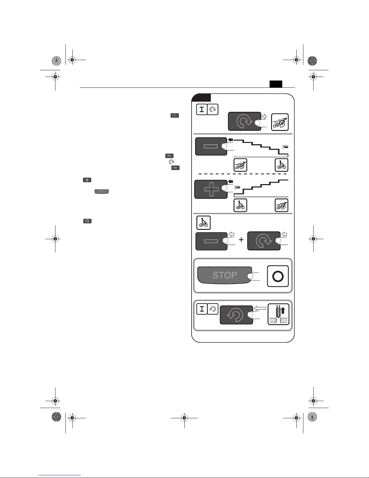
75
es
Encendido y apagado del motor de
taladrar (Figura 14).
Para arrancar el motor de taladrar con giro a
derechas, pulse la tecla con el símbolo „ “.
El motor de taladrar comienza a funcionar a la
velocidad máxima.
La última velocidad ajustada es memorizada
automáticamente (Memory Function). Para
dejar funcionar la herramienta eléctrica a la
velocidad últimamente ajustada, pulse y mantenga pulsada la tecla con el símbolo , y
pulse entonces la tecla con el símbolo .
Para reducir la velocidad pulse la tecla „ “.
Para aumentar la velocidad pulse la tecla
„“.
Para detener el motor de taladrar pulse la
tecla „ “.
No detenga el motor de taladrar durante la
perforación.
Para arrancar el motor de taladrar con giro a
izquierdas, pulse la tecla con el símbolo
„ “. El motor de taladrar funciona mientras
se tenga pulsada la tecla.
Si la alimentación eléctrica se corta estando el
motor de taladrar en marcha (p. ej., al retirar
la batería) un circuito de protección se
encarga de evitar que éste se ponga automáticamente en marcha al volver a alimentarlo.
Vuelva a conectar el motor de taladrar.
En caso de sobrecargar el motor de taladrar
éste se desconecta y tiene que arrancarse de
nuevo.
100l%
85
l%
75
l%
60
l%
50
l%
25
l%
100
l%
85
l%
75
l%
60
l%
50
l%
25
l%
Memory Function
Fig. 14
OBJ_BUCH-0000000261-003.book Page 75 Thursday, January 11, 2018 5:30 PM

76
es
Avance (Figura 15).
Solo aplique la fuerza de avance mínima necesaria para trabajar. Una fuerza de avance excesiva puede provocar la rotura del útil y hacer
que se desprenda la base magnética.
Avance el motor de taladrar conectado
girando a mano la palanca.
La escala la puede Ud. utilizar con la unidad de
medida en “inch” o en “cm”.
cm
inch
1.
inch
cm
3.
2.
Fig. 15
OBJ_BUCH-0000000261-003.book Page 76 Thursday, January 11, 2018 5:30 PM

77
es
Indicaciones para taladrar con
coronas.
Únicamente sacar la corona de la perforación
con el motor en marcha.
Si la corona perforadora llega a atascarse en el
material, detenga el motor de taladrar, y vaya
sacando la corona perforadora girándola con
cuidado en sentido contrario a las agujas del
reloj.
Al terminar de taladrar retire las virutas y el
núcleo resultante de la perforación.
No toque las virutas directamente con la
mano. Siempre realice esto auxiliándose
de un gancho.
¡Peligro de quemadura! La
superficie del imán puede
alcanzar temperaturas muy elevadas. No
toque el imán directamente con las manos.
Al taladrar material compuesto de varias capas
utilice una corona perforadora Slugger ID
apropiada para ello.
Al cambiar la broca no dañe sus filos.
Al taladrar materiales compuestos por capas
de diferente material con coronas perforadoras, vaya retirando el núcleo y las virutas a
medida que va traspasando cada capa.
ATE N CI ÓN
Aviso de falla/
Indicador de imán
Significado Solución
Indicador verde
encendido
La fuerza de sujeción
magnética es suficiente.
Indicador verde
parpadea
La fuerza de sujeción
magnética puede ser
insuficiente.
Al trabajar en materiales de acero de
un grosor inferior a 12 mm es necesario reforzarlos con una placa de
acero adicional para asegurar que sea
suficiente la fuerza magnética de
sujeción.
El indicador se
enciende de color
rojo durante
1 segundo
– Se ha activado el detector de
movimiento
– Se ha activado el detector de
sobrecarga
– Tensión de red incorrecta
Una vez corregida la falla puede
volver a conectarse la máquina.
El indicador parpadea
en rojo 3 veces
No hay señal de tacómetro Si esta falla ocurre con frecuencia
envíe la máquina al servicio técnico
Slugger.
El indicador se
enciende permanentemente de color
rojo
– Frecuencia/tensión de red
incorrecta
– Soporte de taladrar
sobrecalentado
– Tecla bloqueada al intentar
conectarla
Una vez corregida la falla puede
volver a conectarse la máquina.
Si esta falla ocurre con frecuencia
envíe la máquina al servicio técnico
Slugger.
El indicador parpadea
permanentemente de
color rojo
Máquina con falla. Envíe la máquina a un servicio
técnico Slugger
OBJ_BUCH-0000000261-003.book Page 77 Thursday, January 11, 2018 5:30 PM

78
es
Reparación y servicio técnico.
Saque la clavija del enchufe antes de montar o cambiar los útiles y accesorios. Esta medida de seguridad preventiva evita los accidentes que pudieran
presentarse en caso de una puesta en marcha involuntaria.
Piezas sustituibles.
Si fuese preciso, puede sustituir Ud. mismo
las piezas siguientes:
Útiles, depósito de refrigerante
Guía del motor de taladrar (figura 16).
Con el uso de la máquina puede ir aumentando la holgura en la guía del motor de taladrar. Esto
puede dar lugar a que el taladro se deslice por sí mismo a lo largo de la guía del motor de taladrar. Esto puede dificultar el trabajo con la máquina. En ese caso, apriete con cuidado todos los
tornillos de ajuste de la guía del motor de taladrar de forma que el taladro pueda desplazarse
fácilmente a mano, pero sin que logre deslizarse hacia abajo por su propio peso.
ADVERTENCIA
2,5 mm /
3/32 in
2,5 mm /
3/32 in
2,5 mm /
3/32 in
Fig. 16
OBJ_BUCH-0000000261-003.book Page 78 Thursday, January 11, 2018 5:30 PM

79
es
Servicio técnico.
Únicamente deje realizar
los trabajos de manteni-
miento por un profesional. Las líneas y com-
ponentes mal montados pueden suponer un
grave peligro, Deje efectuar el servicio requerido por un servicio técnico Slugger.
En caso de que se dañe la línea
de la herramienta eléctrica es
necesario sustituirla por una línea de refacción
original adquirible a través de uno de los servicios técnicos Slugger.
Solo emplee refacciones originales.
La lista de piezas de refacción actual para esta
herramienta eléctrica la encuentra en internet
bajo www.fein.com.
Limpieza.
Con el fin de evitar acci-
dentes, saque de la alimentación la clavija de la herramienta eléctrica
antes de realizar en la misma cualquier tipo
de trabajo de limpieza o de mantenimiento.
Si el aire ambiente con-
tiene material en polvo
conductor, p. ej., al trabajar metales, puede
que este material llegue a depositarse en el
interior de la herramienta eléctrica. Ello
puede mermar la eficacia del aislamiento de
protección de la herramienta eléctrica. Por
ello, sople con regularidad desde afuera por
las rejillas de refrigeración el interior de la
herramienta eléctrica con aire comprimido
seco y exento de aceite, utilizando en ello
siempre una protección para los ojos. Intercale un interruptor diferencial (RCD) como
medida de protección adicional.
No intente limpiar las rejillas
de refrigeración de la herramienta eléctrica con objetos metálicos en
punta, emplee para ello objetos que no sean
de metal.
No aplique agentes de lim-
pieza ni disolventes que
pudieran atacar a las piezas de plástico.
Algunos de ellos son: Gasolina, tetracloruro
de carbono, disolventes que contengan cloro,
amoniaco, o detergentes domésticos que
contengan amoniaco.
Circuito de refrigeración.
Enjuague el circuito de refrigeración con agua,
límpielo, y vacíelo completamente si tiene
previsto no utilizar la máquina durante más de
dos semanas.
Garantía.
La garantía del producto se realiza de acuerdo a las regulaciones legales vigentes en el país de
adquisición.
Protección del medio ambiente, eliminación.
Las herramientas eléctricas y los accesorios inservibles deberán entregarse a los puntos encargados de su reciclaje ecológico. Para más informaciones consulte a su comercio especializado
habitual.
ADVERTENCIA
ATE N CI ÓN
ADVERTENCIA
ADVERTENCIA
ATE N CI ÓN
ATE N CI ÓN
OBJ_BUCH-0000000261-003.book Page 79 Thursday, January 11, 2018 5:30 PM

80
es
Accesorios incluidos en el suministro (figura 17).
Cuña extractora
Maletín de Transporte
Gancho para virutas
Perno de centrado largo
Cinta tensora
Guarda contra contacto
Portaútiles
105 mm
JMU 137 MQW (**)
JMU 137 MQW (**)
Fig. 17
OBJ_BUCH-0000000261-003.book Page 80 Thursday, January 11, 2018 5:30 PM
 Loading...