

Slugger JCM312U, JCM312auto Instruction Manual
®
© C. & E. FEIN GmbH. Printed in Germany. Figure not obligatory. Subject to technical changes. 3 41 01 169 21 0 BY 2011.09.
®
JCM312U
7 270 38
JCM312auto
7 270 39
2
English _____________ Instruction manual___________________
Español _____________ Instrucciones de uso _________________
3
25
3 41 01 169 21 0.book Seite 2 Mittwoch, 7. September 2011 3:32 15
3
en
For your safety.
Read all safety warnings and all
instructions. Failure to follow
the warnings and instructions may result in
electric shock, fire and/or serious injury.
Save all warnings and instructions for future
reference.
Do not use this power tool before you
have thoroughly read and completely
understood this Instruction Manual, including
the figures, specifications, safety regulations
and the signs indicating DANGER, WARNING and CAUTION.
Only carry out such operations with this
power tool as intended for by the manufacturer. Only use cutting tools and accessories
that have been approved by the manufacturer.
Please also observe the relevant national
industrial safety regulations.
Non-observance of the safety instructions in
the said documentation can lead to electric
shock, burns and/or severe injuries.
This Instruction Manual should be kept for
later use and enclosed with the power tool,
should it be passed on or sold.
SAVE THESE INSTRUCTIONS.
The term “power tool” in the warnings refers
to your mains-operated (corded) power tool
or battery operated (cordless) power tool.
General Safety Rules.
1) Work area safety
a) Keep work area clean and well lit. Clut-
tered or dark areas invite accidents.
b)Do not operate power tools in explosive at-
mospheres, such as in the presence of
flammable liquids, gases or dust. Power
tools create sparks which may ignite the
dust or fumes.
c) Keep children and bystanders away while
operating a power tool. Distractions can
cause you to lose control
2) Electrical safety
a) Power tool plugs must match the outlet.
Never modify the plug in any way. Do not
use any adapter plugs with earthed
(grounded) power tools. Unmodified plugs
and matching outlets will reduce risk of
electric shock.
b)Avoid body contact with earthed or
grounded surfaces such as pipes, radiators,
ranges and refrigerators. There is an in-
creased risk of electric shock if your body
is earthed or grounded.
c) Do not expose power tools to rain or wet
conditions. Water entering a power tool
will increase the risk of electric shock.
d)Do not abuse the cord. Never use the cord
for carrying, pulling or unplugging the
power tool. Keep cord away from heat, oil,
sharp edges or moving parts. Damaged or
entangled cords increase the risk of electric shock.
e) When operating a power tool outdoors, use
an extension cord suitable for outdoor use.
Use of a cord suitable for outdoor use reduces the risk of electric shock.
f) If operating a power tool in a damp location
is unavoidable, use a residual current device (RCD) protected supply. Use of an
RCD reduces the risk of electric shock.
3) Personal safety
a) Stay alert, watch what you are doing and
use common sense when operating a power
tool. Do not use a power tool while you are
tired or under the influence of drugs, alcohol or medication. A moment of inatten-
tion while operating power tools may result in serious personal injury.
b)Use safety equipment. Always wear eye
protection. Safety equipment such as dust
mask, non-skid safety shoes, hard hat, or
hearing protection used for appropriate
conditions will reduce personal injuries.
WARNING
3 41 01 169 21 0.book Seite 3 Mittwoch, 7. September 2011 3:32 15
4
en
c) Avoid accidental starting. Ensure the switch
is in the off-position before plugging in.
Carrying power tools with your finger on
the switch or plugging in power tools that
have the switch on invites accidents.
d)Remove any adjusting key or wrench before
turning the power tool on. A wrench or a
key left attached to a rotating part of the
power tool may result in personal injury.
e) Do not overreach. Keep proper footing and
balance at all times. This enables better
control of the power tool in unexpected
situations.
f) Dress properly. Do not wear loose clothing
or jewelery. Keep your hair, clothing and
gloves away from moving parts. Loose
clothes, jewelery or long hair can be
caught in moving parts.
g) If devices are provided for the connection of
dust extraction and collection facilities, ensure these are connected and properly
used. Use of these devices can reduce
dust-related hazards.
4) Power tool use and care
a) Do not force the power tool. Use the correct
power tool for your application. The cor-
rect power tool will do the job better and
safer at the rate for which it was designed.
b)Do not use the power tool if the switch does
not turn it on and off. Any power tool that
cannot be controlled with the switch is
dangerous and must be repaired.
c) Disconnect the plug from the power source
and/or the battery pack from the power tool
before making any adjustments, changing
accessories, or storing power tools. Such
preventive safety measures reduce the
risk of starting the power tool accidentally.
d)Store idle power tools out of the reach of
children and do not allow persons unfamiliar with the power tool or these instructions
to operate the power tool. Power tools are
dangerous in the hands of untrained users.
e) Maintain power tools. Check for misalign-
ment or binding of moving parts, breakage
of parts and any other condition that may
affect the power tools operation. If damaged, have the power tool repaired before
use. Many accidents are caused by poorly
maintained power tools.
f) Keep cutting tools sharp and clean. Prop-
erly maintained cutting tools with sharp
cutting edges are less likely to bind and are
easier to control.
g) Use the power tool, accessories and tool
bits etc., in accordance with these instructions and in the manner intended for the
particular type of power tool, taking into
account the working conditions and the
work to be performed. Use of the power
tool for operations different from those
intended could result in a hazardous situation.
5) Service
a) Have your power tool serviced by a quali-
fied repair person using only identical replacement parts. This will ensure that the
safety of the power tool is maintained.
3 41 01 169 21 0.book Seite 4 Mittwoch, 7. September 2011 3:32 15
5
en
Special safety instructions.
Wear personal protective equipment. Depending on the application, use a face shield,
safety goggles or safety glasses. Wear ear protection. The safety glasses must be capable of
protecting against flying particles generated
by the various operations. Prolonged exposure to high intensity noise may cause loss of
hearing.
Secure the power tool with the safety strap
supplied if there is danger of it falling, especially for work carried out at elevated heights,
when drilling horizontally or above the head. If
there is a power loss, or the power plug is
pulled out, the magnetic holding power is not
maintained.
When working overhead or on vertical surfaces, the coolant container must not be used.
Use Slugger Cutting Paste instead. Liquids
penetrating your electric power tool may
cause electric shock.
Avoid touching the drilled core that is automatically ejected by the pilot pin when the working
procedure is finished. Contact with the core
when it is hot, or if it falls, can cause personal
injuries.
Operate the power tool only from grounded
contact sockets that comply with the specifications. Do not use any connection cables that are
damaged; use extension cables with a grounded contact that are checked at regular intervals. A grounded conductor without
continuity can cause an electric shock.
Do not machine any material containing asbestos. Asbestos is carcinogenic.
To prevent injuries, always keep your hands,
clothing, etc. away from rotating swarf. The
swarf can cause injuries. Always use the chipping protector.
Do not attempt to remove the cutting tool if it
does not turn. This can lead to serious injuries.
Do not rivet or screw any name-plates or signs
onto the power tool. If the insulation is dama-
ged, protection against an electric shock will
be ineffective. Adhesive labels are recommended.
Do not use accessories which are not specifically designed and recommended by the power
tool manufacturer. Safe operation is not ensu-
red merely because an accessory fits your
power tool.
Clean the ventilation openings on the power
tool at regular intervals using non-metal tools.
The blower of the motor draws dust into the
housing. An excessive accumulation of metallic dust can cause an electrical hazard.
Hold power tool by insulated gripping surfaces
when performing an operation where the cutting accessory may contact hidden wiring or its
own cord. Cutting accessory contacting a
“live” wire will make exposed metal parts of
the power tool “live” and shock the operator.
Before putting into operation, check the power
connection and the power plug for damage.
Handling hazardous dusts
When working with power
tools, such as when grinding,
sanding, polishing, sawing or for other work
procedures where material is removed, dusts
develop that are both hazardous to one’s health
and can spontaneously combust or be explosive.
Contact with or inhaling some dust types can
trigger allergic reactions to the operator or
bystanders and/or lead to respiratory infections, cancer, birth defects or other reproductive harm.
Examples of such materials which contain
chemicals that can produce hazardous dusts,
are:
– Asbestos and materials containing asbestos
– Lead-containing coatings, some wood types
such as beech and oak
– Minerals and metal
– Silicate particles from bricks, concrete and
other materials containing stone
– Solvent from solvent-containing paint/var-
nish
– Arsenic, chromium and other wood pre-
servatives
WARNING
3 41 01 169 21 0.book Seite 5 Mittwoch, 7. September 2011 3:32 15
6
en
– Materials for pesticide treatment on boat
and ship hulls.
To minimize the unwanted intake of these
materials:
– Use dust extraction matched appropriately
for the developing dust.
– Use personal protective equipment, such as
a P2 filter-class dust protection mask.
– Provide for good ventilation of the work-
place.
The risk from inhaling dusts depends on the
frequency how often these materials are
worked. Materials containing asbestos may
only be worked by specialists.
Wood and light-metal dust can
cause spontaneous combustion
or explosions.
Hot mixtures of sanding dust and paint/varnish residuals or other chemical materials in
the filter bag or the vac filter can self-ignite
under unfavourable conditions, such as sparking from sanding metal, continuous sunlight
or high ambient temperatures. To prevent
this:
– Avoid overheating the material being
sanded and the power tool.
– Empty the dust collector/container in time.
– Observe the material manufacturer’s work-
ing instructions.
Observe the relevant regulations for the
materials being worked.
Emission values for sound (Two-figure – specifications as per ISO 4871)
CAUTION
Sound emission JCM312U JCM312auto
A-weighted emission pressure power level
measured at the workplace LpA (re 20 µPa), in
decibels 84 84
Measuring uncertainty KpA, in decibels 3 3
Measured A-weighted sound power level LwA
(re 1 pW), in decibels 95 95
Measuring uncertainty KwA, in decibels 3 3
Measured C-weighted peak sound pressure
level L
pCpeak
, in decibels 101 101
Measuring uncertainty K
pCpeak
, in decibels 3 3
REMARK: The sum of the measured emission value and respective measuring inaccuracy represents the upper limit of the values that can occur during measuring.
Wear ear protection!
Measured values determined in accordance with the corresponding product standard.
3 41 01 169 21 0.book Seite 6 Mittwoch, 7. September 2011 3:32 15
7
en
Extension cord
If the use of an extension cord
is required, its length and conductor cross-section must be adequate for the
application in order to prevent a voltage drop in
the extension cord, power loss and overheating
of the power tool. Otherwise, the extension
cable and power tool are prone to electrical
danger, and the working efficiency is
decreased.
Recommended dimensions of extension cords
at an operating voltage of 120 V – single-phase
a. c., with only one power tool
JCM312U/JCM312auto connected:
Intended use of the power tool.
Magnetic base drill for drilling with annular
tools and twist drill bits, reaming, countersinking and tapping on materials with surfaces
suitable for magnets in weather-protected
environments using the cutting tools and
accessories recommended by the manufacturer.
Operation of the power tool off power generators.
Operate the power tool only off
a.c. generators with sufficient power
output that do not have any distortion of the
voltage curve.
Operating the power tool off
power generators whose noload speed exceeds the voltage value on the
type plate of the power tool is prohibited.
Max. cable length, ft Max. cable length, m
≤ 100 100
–200
≤ 30 30
– 60
Min. conductor size
(A.W.G.)
Min. conductor
cross-section, mm
2
14 12 2.5 4
CAUTION
WARNING
3 41 01 169 21 0.book Seite 7 Mittwoch, 7. September 2011 3:32 15
8
en
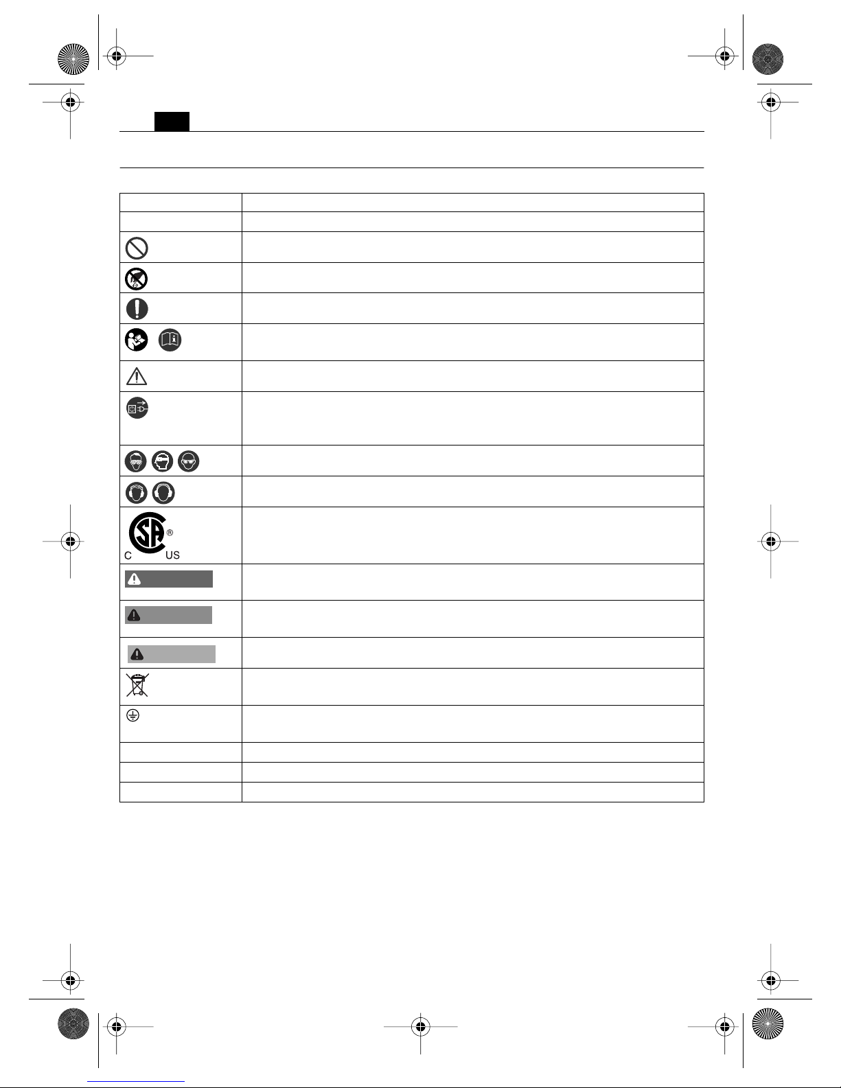
Symbols.
Symbol Explanation
➤
Action to be taken by the user
General prohibition sign. This action is forbidden!
Do not touch the rotating parts of the power tool.
Follow the instructions in the adjacent text!
Be absolutely sure to read the enclosed documentation such as the
Instruction Manual and the General Safety Instructions.
Observe the information in the adjacent text or graphic!
Before commencing this working step, pull the power plug out of the
socket. Otherwise there will be danger of injury if the power tool should
start unintentionally.
Use eye protection during operation.
Use ear protection during operation.
This symbol confirms the certification of this product for the USA and
Canada.
This sign warns of a directly imminent, dangerous situation. A false reaction can cause a severe or fatal injury.
This sign indicates a possible dangerous situation that could cause severe
or fatal injury.
This sign warns of a possible dangerous situation that could cause injury.
Worn out power tools and other electrotechnical and electrical products
should be sorted separately for environmentally-friendly recycling.
Product with basic insulation and exposed, conductive parts additionally
connected to the ground conductor.
~ or a. c. Alternating current
1 ~ Alternating current single-phase
Ø Diameter of a round part
DANGER
WARNING
CAUTION
3 41 01 169 21 0.book Seite 8 Mittwoch, 7. September 2011 3:32 15
9
en
Character Unit of measure, national Explanation
n
o
rpm Revolution speed at no-load
P W Electric output
Hz Frequency
f V Electric voltage
I A Electric current intensity
° Angle width
m lbs Mass
l ft, in Length, height, depth, diameter and tapping
m, s, kg, A, mm, V, W,
Hz, N, °C, dB, rpm, m/s
2
Basic and derived units of measure from the international system of units SI.
3 41 01 169 21 0.book Seite 9 Mittwoch, 7. September 2011 3:32 15
10
en
Technical description and specifications.
Before mounting or replacing cutting tool or accessories, pull the power plug. This
preventive safety measure rules out the danger of injuries through accidental
starting of the power tool.
All accessories described or shown in this instruction manual will not be included with your
power tool.
WARNING
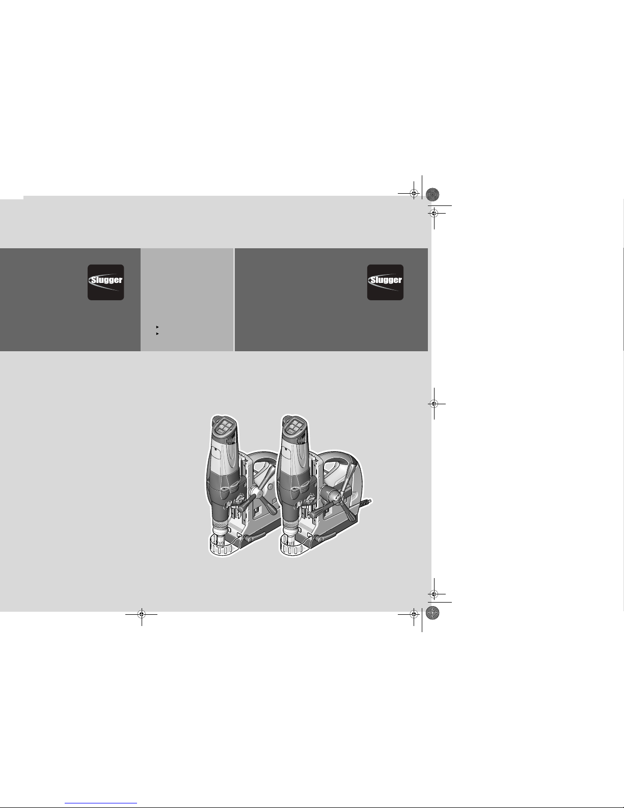
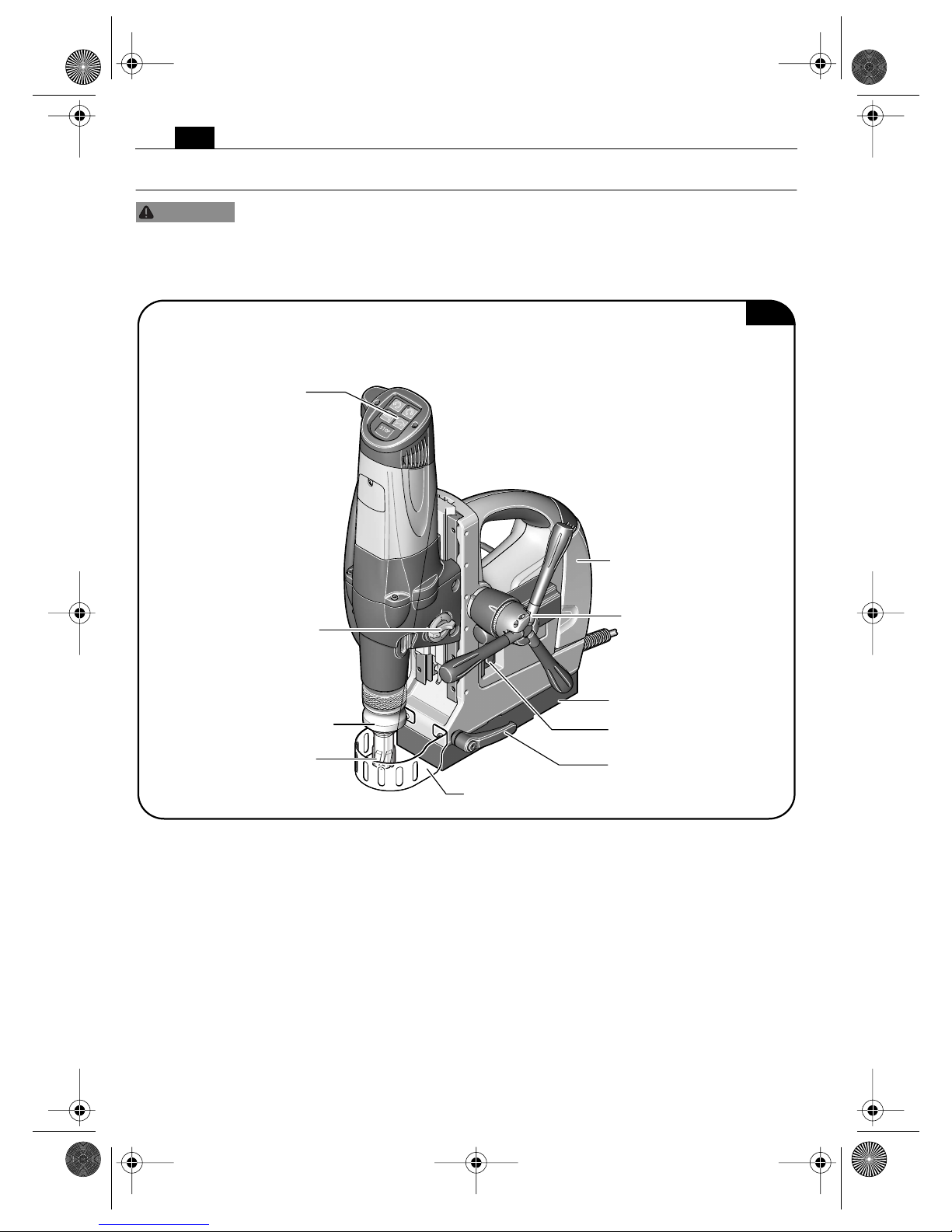
Fig. 1
JCM312auto
Coolant container
Spoke handle
with feed motor
Magnetic base
Magnet ON/OFF switch
Clamping lever
Chip guard
QuickIN Max
tool holder
Gear switch
Cutting tool
Viseo Touch Pad
3 41 01 169 21 0.book Seite 10 Mittwoch, 7. September 2011 3:32 15
11
en
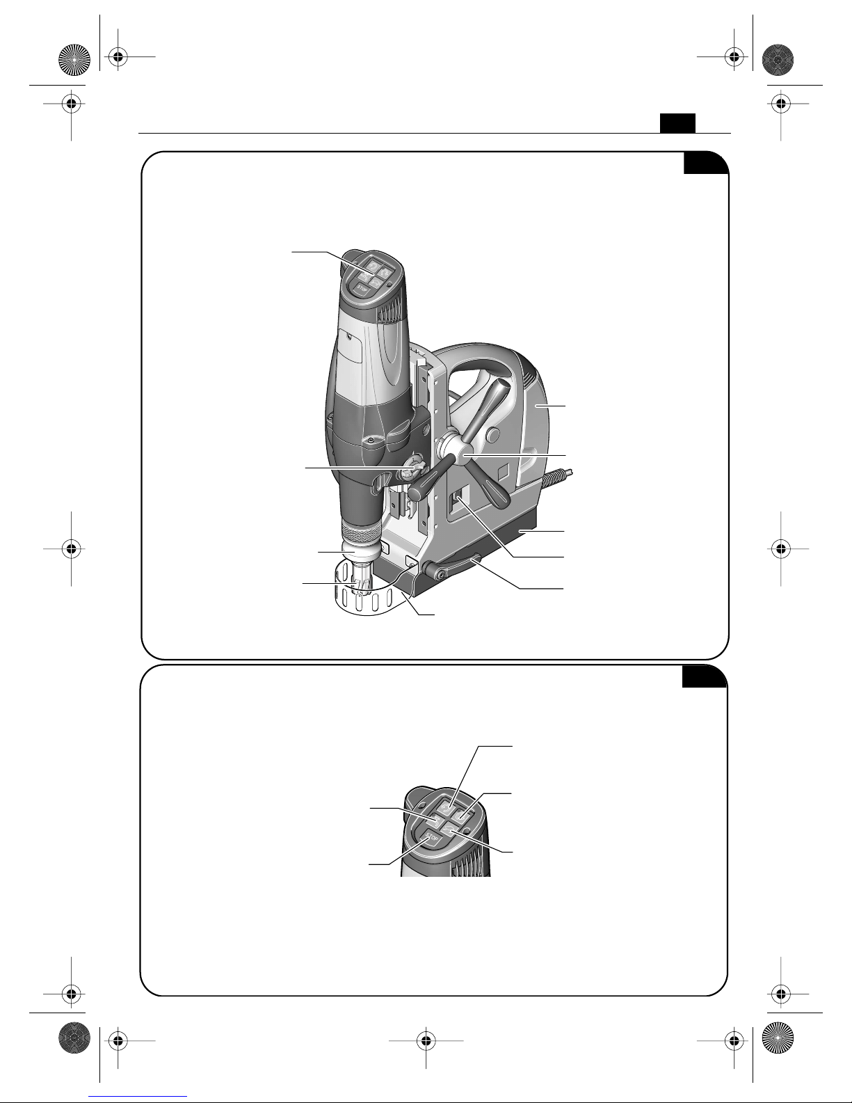
Viseo Touch Pad
Fig. 2
JCM312U
Coolant container
Spoke handle
Magnetic base
Magnet ON/OFF switch
Clamping lever
Chip guard
QuickIN Max
tool holder
Gear switch
Cutting tool
Button for cooling lubricant
supply
Button for speed reduction
Stop motor button
Button for starting the drill
motor in clockwise direction
Button for starting the drill
motor in counterclockwise
direction (tip operation)
Fig. 3
3 41 01 169 21 0.book Seite 11 Mittwoch, 7. September 2011 3:32 15
12
en
Type JCM312U JCM312auto
Reference number 7 270 38 7 270 39
Current consumption 15 A 15 A
Power supply type 1 ~ 1 ~
No-load speed (Clockwise)
1st gear 180 rpm 180 rpm
2nd gear 260 rpm 260 rpm
3rd gear 580 rpm 580 rpm
No-load speed (Counterclockwise)
1st gear 180 rpm 180 rpm
2nd gear 260 rpm 260 rpm
3rd gear 580 rpm 580 rpm
Weight according to EPTA-Procedure 01/2003 25.4 kg
55.9 lbs
26.4 kg
58 lbs
Class of protection I I
Core drilling capacity in steel - TCT (carbide tipped
cutter)
12 – 80 mm
7
/16 in–3 1/8 in
12 – 80 mm
7
/16 in–3 1/8 in
Core drilling capacity in steel – HSS (high speed
steel)
12 – 65 mm
7
/16 in–2 9/16 in
12 – 65 mm
7
/16 in–2 9/16 in
Drilling capacity in steel – HSS twist drill bit 32 mm
1 1/4 in
32 mm
1 1/4 in
Bolt hole diameter max. M27, 1 1/8 in M27, 1 1/8 in
Max. twist drill diameter with the supplied chuck 13 mm
1
/2 in
13 mm
1
/2 in
Reamer diameter 31 mm
1 3/16 in
31 mm
1 3/16 in
Counterboring diameter 50 mm
2 in
50 mm
2 in
3 41 01 169 21 0.book Seite 12 Mittwoch, 7. September 2011 3:32 15
13
en
Assembly instructions.
Filling coolant tank.
Before mounting or replacing cutting tools or accessories, pull the power plug.
This preventive safety measure rules out the danger of injuries through accidental starting of the power tool.
Prevent the flow of liquid along the cable into the socket or into the core drill,
as this can lead to electric shock. Tie a bow in the cord near the plug so that
any liquid can drip off.
Only use water soluble cutting fluid that is capable of being pumped like Slugger Cutting Fluid.
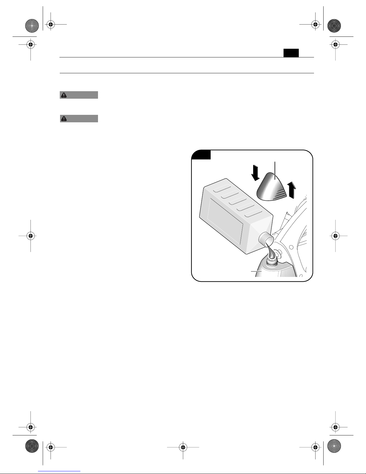
Filling the mounted coolant tank (Fig. 4).
➤ Pull off the upper closing cap of the
coolant tank.
➤ Fill in pump-feedable water soluble
Slugger Cutting Fluid. Do not use oil!
➤ Mount the upper closing cap firmly
onto the coolant tank.
WARNING
WARNING
Fig. 4
Coolant container
Upper closing cap
3 41 01 169 21 0.book Seite 13 Mittwoch, 7. September 2011 3:32 15
14
en
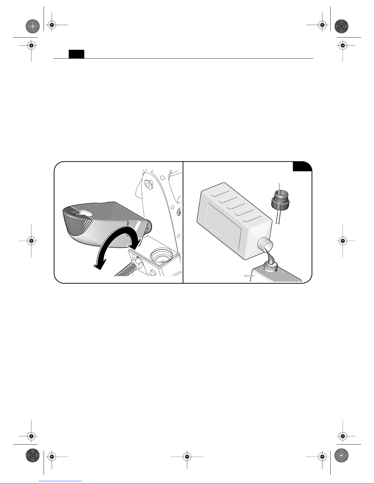
Filling the removed coolant tank. (Fig. 5).
➤ Pull the empty coolant tank out of drill
stand housing of the magnetic base drill.
➤ Unscrew the bottom closing cap from
the coolant tank.
➤ Fill in pump-feedable water soluble
Slugger Cutting Fluid. Do not use oil!
➤ Firmly screw the bottom closing cap
back on to the coolant tank.
➤ Insert the filled coolant tank into the
holder on the drill stand housing intended for this purpose.
Fig. 5
Coolant container
Bottom closing cap
3 41 01 169 21 0.book Seite 14 Mittwoch, 7. September 2011 3:32 15
15
en
Changing the tool.
Secure the power tool with the safety strap supplied at all times, especially for
work carried out at elevated heights, when drilling horizontally or above the head.
If there is a power loss, or the power plug is pulled out, the magnetic holding power is not
maintained.
Before mounting or replacing cutting tools or accessories, pull the power plug.
This preventive safety measure rules out the danger of injuries through accidental starting of the power tool.
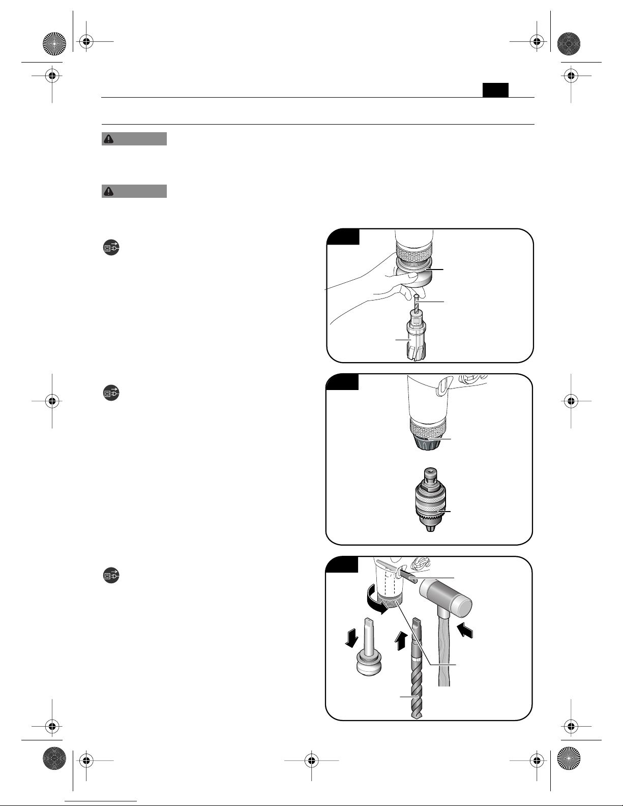
Carbide tipped cutter (Fig. 6).
➤ Insert the pilot pin into the carbide tip-
ped cutter.
➤ Pull the QuickIN Max clamping sleeve
of the tool holder downward. Insert the
carbide tipped cutter with the pilot pin.
Do not touch the sharp edges of the carbide tipped cutter.
Key-type drill chuck (Fig. 7).
➤ Turn the QuickIN clamping sleeve of
the tool holder leftward and insert the
geared drill chuck.
Twist drill bit (Fig. 8).
➤ Turn the knurled nut until it spins
through.
➤ Place the drift in position and apply a
hammer blow to remove the tool holder.
➤ Clean the inside cone of the output
shaft and insert the twist drill bit.
WARNING
WARNING
Fig. 6
QuickIN Max.
tool holder
Pilot pin
Carbide tipped cutter
Fig. 7
QuickIN
tool holder
Key-type drill
chuck
1.
2.
3.
4.
Fig 8
Twist drill bit
Drift
Knurled nut
3 41 01 169 21 0.book Seite 15 Mittwoch, 7. September 2011 3:32 15
 Loading...