

®
© C. & E. FEIN GmbH. Printed in USA. Figure not obligatory. Subject to technical changes. 3 41 01 198 21 0 BY 2013.11.
®
FEIN Service
USA
FEIN Power Tools Inc.
1030 Alcon Street
Pittsburgh, PA 15220
Telephone: (412) 922-8886
Toll Free: 1-800-441-9878
www.feinus.com
Headquarter
C. & E. FEIN GmbH
Hans-Fein-Straße 81
D-73529 Schwäbisch Gmünd-Bargau
www.fein.com
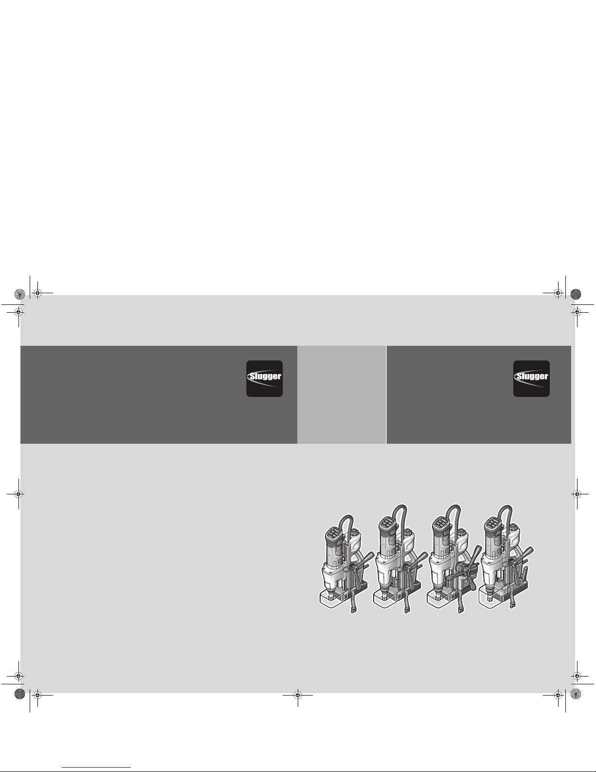
JCM 200 QX 7 270 45
JCM 200 U 7 270 44
JCM 200 auto 7 270 46
JCM 256 U 7 270 47
OBJ_DOKU-0000003391-002.fm Page 1 Monday, November 18, 2013 10:44 AM
2
Instruction Manual
Instrucciones de uso
en
3
es
26
OBJ_BUCH-0000000130-002.book Page 2 Monday, November 18, 2013 10:38 AM
3
en
en
For your safety.
Read all safety warnings and
all instructions. Failure to fol-
low the warnings and instructions may result
in electric shock, fire and/or serious injury.
Save all warnings and instructions for futurereference.
Do not use this power tool before you
have thoroughly read and completely
understood this Instruction Manual, including
the figures, specifications, safety regulations
and the signs indicating DANGER, WARNING and CAUTION.
Only carry out such operations with this
power tool as intended for by the manufacturer. Only use cutting tools and accessories
that have been approved by the manufacturer.
Please also observe the relevant national
industrial safety regulations.
Non-observance of the safety instructions in
the said documentation can lead to an electric
shock, burns and/or severe injuries.
This Instruction Manual should be kept for
later use and enclosed with the power tool,
should it be passed on or sold.
SAVE THESE INSTRUCTIONS.
The term “power tool” in the warnings refers
to your mains-operated (corded) power tool
or battery operated (cordless) power tool.
General safety rules.
1) Work area safety
a)Keep work area clean and well lit. Clut-
tered or dark areas invite accidents.
b)Do not operate power tools in explosive
atmospheres, such as in the presence of
flammable liquids, gases or dust. Power
tools create sparks which may ignite the
dust or fumes.
c) Keep children and bystanders away
while operating a power tool. Distrac-
tion can cause you to lose control.
2) Electrical safety
a)Power tool plugs must match the outlet.
Never modify the plug in any way. Do not
use any adapter plugs with earthed
(grounded) power tools. Unmodified
plugs and matching outlets will reduce
risk of electric shock.
b)Avoid body contact with earthed or
grounded surfaces such as pipes, radiators, ranges and refrigerators. There is
an increased risk of electric shock if
your body is earthed or grounded.
c) Do not expose power tools to rain or wet
conditions. Water entering a power tool
will increase the risk of electric shock.
d)Do not abuse the cord. Never use the
cord for carrying, pulling or unplugging
the power tool. Keep cord away from
heat, oil, sharp edges or moving parts.
Damaged or entangled cords increase
the risk of electric shock.
e) When operating a power tool outdoors,
use an extension cord suitable for outdoor
use. Use of a cord suitable for outdoor
use reduces the risk of electric shock.
f) If operating a power tool in a damp loca-
tion is unavoidable, use a residual current device (RCD) protected supply. Use
of an RCD reduces the risk of electric
shock.
3) Personal safety
a)Stay alert, watch what you are doing
and use common sense when operating
a power tool. Do not use a power tool
while you are tired or under the influence of drugs, alcohol or medication. A
moment of inattention while operating
power tools may result in serious personal injury.
b)Use personal protective equipment.
Always wear eye protection. Protective
equipment such as dust mask, non-skid
safety shoes, hard hat, or hearing protection used for appropriate conditions
will reduce personal injuries.
c) Prevent unintentional starting. Ensure
the switch is in the off-position before
connecting to power source and/or battery pack, picking up or carrying the
tool. Carrying power tools with your
finger on the switch or energising
power tools that have the switch on
invites accidents.
d)Remove any adjusting key or wrench
before turning the power tool on. A
wrench or a key left attached to a rotating part of the power tool may result in
personal injury.
WARNING
OBJ_BUCH-0000000130-002.book Page 3 Monday, November 18, 2013 10:38 AM
4
en
e) Do not overreach. Keep proper footing
and balance at all times. This enables
better control of the power tool in
unexpected situations.
f) Dress properly. Do not wear loose cloth-
ing or jewelery. Keep your hair, clothing
and gloves away from moving parts.
Loose clothes, jewelry or long hair can
be caught in moving parts.
g)If devices are provided for the connec-
tion of dust extraction and collection
facilities, ensure these are connected
and properly used. Use of dust collec-
tion can reduce dust-related hazards.
4) Power tool use and care
a)Do not force the power tool. Use the cor-
rect power tool for your application. The
correct power tool will do the job better and safer at the rate for which it was
designed.
b) Do not use the power tool if the switch
does not turn it on and off. Any power
tool that cannot be controlled with the
switch is dangerous and must be repaired.
c) Disconnect the plug from the power
source and/or the battery pack from the
power tool before making any adjustments, changing accessories, or storing
power tools. Such preventive safety
measures reduce the risk of starting the
power tool accidentally.
d) Store idle power tools out of the reach of
children and do not allow persons unfamiliar with the power tool or these
instructions to operate the power tool.
Power tools are dangerous in the hands
of untrained users.
e) Maintain power tools. Check for mis-
alignment or binding of moving parts,
breakage of parts and any other condition that may affect the power tool’s
operation. If damaged, have the power
tool repaired before use. Many accidents
are caused by poorly maintained power
tools.
f) Keep cutting tools sharp and clean.
Properly maintained cutting tools with
sharp cutting edges are less likely to
bind and are easier to control.
g) Use the power tool, accessories and tool
bits etc. in accordance with these
instructions, taking into account the
working conditions and the work to be
performed. Use of the power tool for
operations different from those intended
could result in a hazardous situation.
5) Service
a)Have your power tool serviced by a qual-
ified repair person using only identical
replacement parts. This will ensure that
the safety of the power tool is maintained.
Special safety instructions.
Wear protective equipment. Depending on the
application, wear face shield or safety goggles. Wear hearing protection. The safety
glasses/goggles must be suitable to protect
against the particles emitted from different
operations. Continuous high exposure to
noise can lead to loss of hearing.
Replace the protective cable bushing immediately when damaged. A defective protective
cable bushing can lead to overheating of the
machine and to an emergency stop.
Mount the swarf protector to the machine
before beginning to work.
Secure the power tool with the safety strap
supplied at all times, especially for work carried out at elevated heights, when drilling horizontally or above the head. If there is a power
loss, or the power plug is pulled out, the magnetic holding power is not maintained.
When working overhead or on vertical surfaces, the coolant container must not be used.
Use Slugger Cutting Paste instead. Liquids
penetrating your electric power tool maycause electric shock.
Avoid touching the drilled core that is automatically ejected by the pilot pin when the
working procedure is finished. Contact with
the core when it is hot, or if it falls, can cause
personal injuries.
Operate the power tool only from grounded
contact sockets that comply with the specifications. Do not use any connection cables
that are damaged; use extension cables with
a grounded contact that are checked at regular intervals. A ground conductor without
continuity can cause an electric shock.
OBJ_BUCH-0000000130-002.book Page 4 Monday, November 18, 2013 10:38 AM
5
en
To prevent injuries, always keep your hands,
clothing, etc. away from rotating swarf. The
swarf can cause injuries. Always use the chipping protector.
Do not attempt to remove the cutting tool if it
does not turn. This can lead to serious injuries.
Hold power tool by insulated gripping surfaces when performing an operation where
the cutting accessory may contact hidden
wiring or its own cord. Cutting accessory con-
tacting a “live” wire will make exposed metal
parts of the power tool “live” and shock the
operator.
Beware of any concealed electric cables, gas
or water conduits. Check the working area
before commencing work, e. g. with a metal
detector.
Do not machine any material containing
asbestos. Asbestos is cancerogenic.
Do not rivet or screw any name-plates or
signs onto the power tool. If the insulation is
damaged, protection against an electric shock
will be ineffective. Adhesive labels are recommended.
Do not use accessories which are not specifically designed and recommended by the
power tool manufacturer. Safe operation is
not ensured merely because an accessory fits
your power tool.
Clean the ventilation openings on the power
tool at regular intervals using non-metal
tools. The blower of the motor draws dust
into the housing. An excessive accumulation
of metallic dust can cause an electrical hazard.
Before putting into operation, check the
power connection and the power plug for
damage.
Recommendation: The tool should always be
supplied with power via a residual current
device (RCD) with a rated current of 30 mA or
less.
Handling hazardous dusts.
When working with power
tools, such as when grinding,
sanding, polishing, sawing or for other work
procedures where material is removed, dusts
develop that are both hazardous to one’s
health and can spontaneously combust or be
explosive.
Contact with or inhaling some dust types can
trigger allergic reactions to the operator or
bystanders and/or lead to respiratory infections, cancer, birth defects or other reproductive harm.
Examples of such materials which contain
chemicals that can produce hazardous dusts,
are:
– Asbestos and materials containing asbes-
tos;
– Lead-containing coatings, some wood
types such as beech and oak;
– Minerals and metal;
– Silicate particles from bricks, concrete and
other materials containing stone;
– Solvent from solvent-containing paint/
varnish;
– Arsenic, chromium and other wood pre-
servatives;
– Materials for pesticide treatment on boat
and ship hulls;
– Stainless steel dust, metal dust and non-
ferrous metal dust;
To minimize the unwanted intake of these
materials:
– Use dust extraction matched appropriately
for the developing dust.
– Use personal protective equipment, such
as a P2 filter-class dust protection mask.
– Provide for good ventilation of the work-
place.
The risk from inhaling dusts depends on how
often these materials are worked. Materials
containing asbestos may only be worked by
specialists.
Wood and light-metal dust can
cause spontaneous combus-
tion or explosions.
Hot mixtures of sanding dust and paint/varnish residuals or other chemical materials in
the filter bag or the vac filter can self-ignite
under unfavourable conditions, such as sparking from sanding metal, continuous sunlight
or high ambient temperatures. To prevent
this:
– Avoid overheating the material being
sanded and the power tool.
– Empty the dust collector/container rou-
tinely.
WARNING
CAUTION
OBJ_BUCH-0000000130-002.book Page 5 Monday, November 18, 2013 10:38 AM

6
en
– Observe the material manufacturer’s
working instructions.
– Observe the relevant regulations for the
materials being worked.
Emission values for sound (Two-figure – specifications as per ISO 4871)
Extension cable.
If the use of an extension cord
is required, its length and conductor cross-section must be adequate for the
application in order to prevent a voltage drop
in the extension cord, power loss and overheating of the power tool. Otherwise, the
extension cable and power tool are prone to
electrical danger, and the working efficiency is
decreased.
Recommended dimensions of extension cords
at an operating voltage of 120 V – singlephase a. c., with only JCM 200 QX, JCM 200 U,
JCM 200 auto, JCM 256 U connected:
Sound emission JCM 200 QX JCM 200 U JCM 200 auto JCM 256 U
A-weighted emission pressure
power level measured at the workplace
L
pA
(re 20 μPa), in decibels 82.4 82.4 82.4 82.4
Measuring uncertainty
K
pA
, in deci-
bels 33 33
Measured A-weighted sound
power level
L
wA
(re 1 pW), in
decibels 93.4 93.4 93.4 93.4
Measuring uncertainty
K
wA
, in
decibels 3 3 3 3
C-weighted peak sound pressure
level measured at the workplace
L
pCpeak
, in decibels 97.0 97.0 97.0 97.0
Measuring uncertainty
K
pCpeak
, in
decibels 3 3 3 3
Mean vibrational value
(core drilling)
– m/s
2
– ft/s
2
< 2.5
8.3
< 2.5
8.3
< 2.5
8.3
< 2.5
8.3
Measuring uncertainty
K
, in
– m/s
2
– ft/s
2
1.5
4.9
1.5
4.9
1.5
4.9
1.5
4.9
REMARK: The sum of the measured emission value and respective measuring inaccuracy represents the upper limit of the values that can occur during measuring.
Wear hearing protection!
Measured values determined in accordance with the corresponding product standard.
WARNING
Max. cable length, ft Max. cable length, m
≤ 100 100
–200
200
–300
≤ 30 30
–6060–100
Min. conductor size
A.W.G.
Min. conductorcrosssection, mm
2
16 14 12 1.5 2.5 4
OBJ_BUCH-0000000130-002.book Page 6 Monday, November 18, 2013 10:38 AM
7
en
Intended use of the power tool:
Magnetic core drill unit for drilling with core
drill bits and solid drill bits, reaming, countersinking and tapping on materials with surfaces
suitable for magnets in weather-protected
environments using the application tools and
accessories recommended by Slugger.
Operation of the power tool off power generators.
This power tool is also suitable for use
with AC generators with sufficient power
output that correspond to the Standard
ISO 8528, design type G2. This Standard is
particularly not complied with when the socalled distortion factor exceeds 10 %. When
in doubt, please refer to the generator
instruction/specification guide.
Operating the power tool off
power generators whose noload speed exceeds the voltage value on the
type plate of the power tool is prohibited.
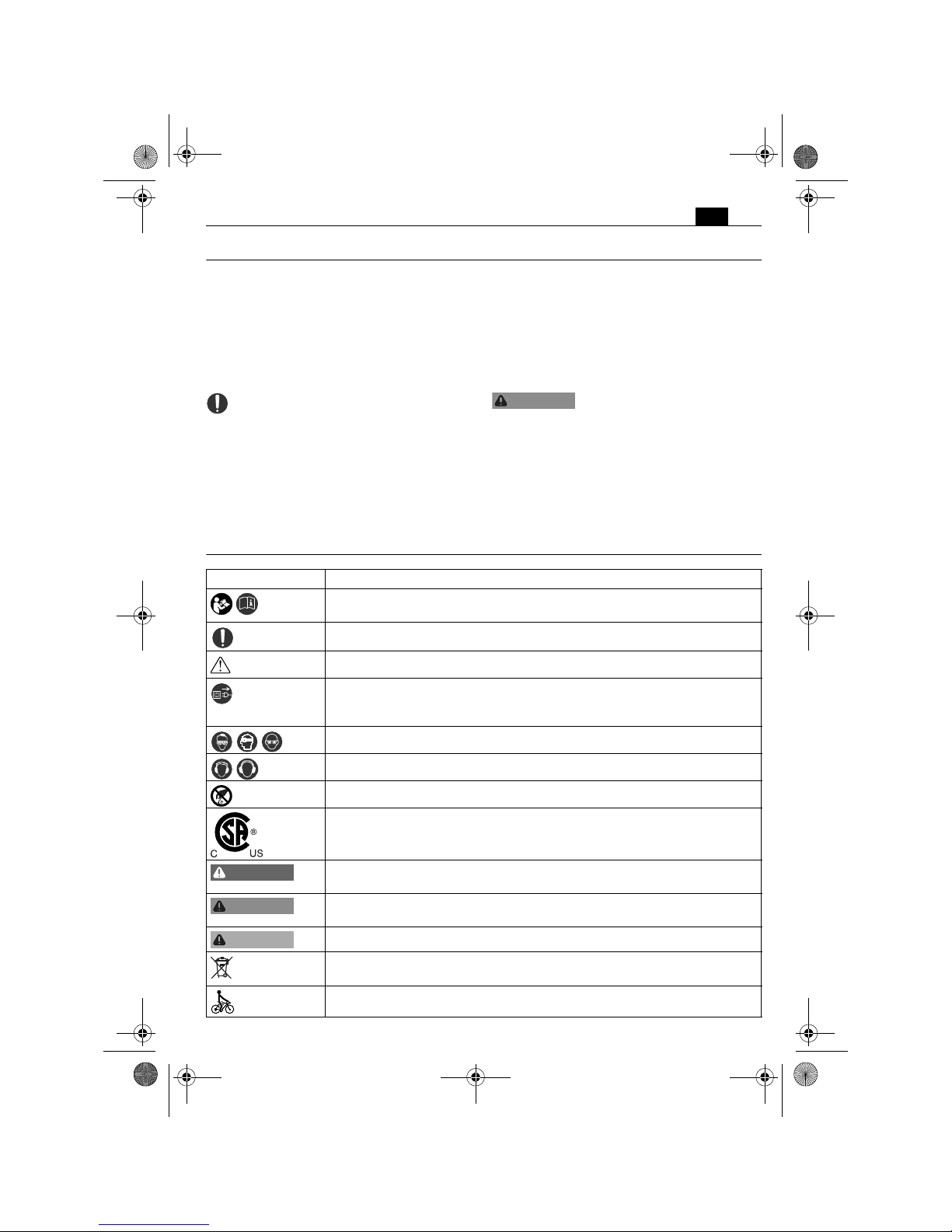
Symbols.
WARNING
Symbol, character Explanation
Make sure to read the enclosed documents such as the Instruction Manual and the General Safety Instructions.
Observe the instructions in the text or graphic opposite!
Observe the instructions in the text or graphic opposite!
Before commencing this working step, pull the power plug out of thesocket. Otherwise there will be danger of injury if the power tool should
start unintentionally.
Use eye protection during operation.
Use ear protection during operation.
Do not touch the rotating parts of the power tool.
This symbol confirms the certification of this product for the USA and
Canada.
This sign warns of a directly imminent, dangerous situation. A false reaction can cause a severe or fatal injury.
This sign indicates a possible dangerous situation that could cause severe
or fatal injury.
This sign warns of a possible dangerous situation that could cause injury.
Worn out power tools and other electrotechnical and electrical products
should be sorted separately for environmentally-friendly recycling.
Low speed
DANGER
WARNING
CAUTION
OBJ_BUCH-0000000130-002.book Page 7 Monday, November 18, 2013 10:38 AM
8
en
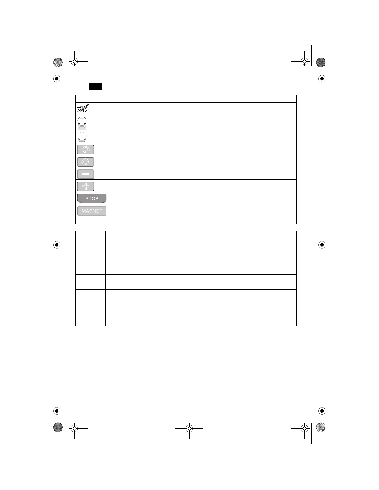
High speed
Magnetic holding power, sufficient
Magnetic holding power, insufficient
Start drill motor. Rotation direction: clockwise
Start drill motor in inch mode. Rotation direction: counterclockwise
Speed reduction in steps
Speed increase in steps
Stop motor
Switches the magnet On/Off
* Value applies for JCM 200 auto in manual machine operation
Symbol, character Explanation
Character Unit of measurement,
national
Explanation
n
0
rpm; /min; min-1; r/min No-load speed
P
W Electrical power
°Angle width
U V Electric voltage
f Hz Frequency
I
A Electric current intensity
m
lbs Mass
l ft, in Length, width, height, depth, diameter or thread
Ø ft, in Diameter of a round part
m, s, kg, A, mm, V, W,
Hz, N, °C, dB, min, m/s
2
Basic and derived units of measurement from the
international system of units SI.
OBJ_BUCH-0000000130-002.book Page 8 Monday, November 18, 2013 10:38 AM
9
en
Technical description and specifications.
Before mounting or replacing cutting tool or accessories, pull the power plug.
This preventive safety measure rules out the danger of injuries through accidental starting of the power tool.
All accessories described or shown in this instruction manual will not be included with yourpower tool.
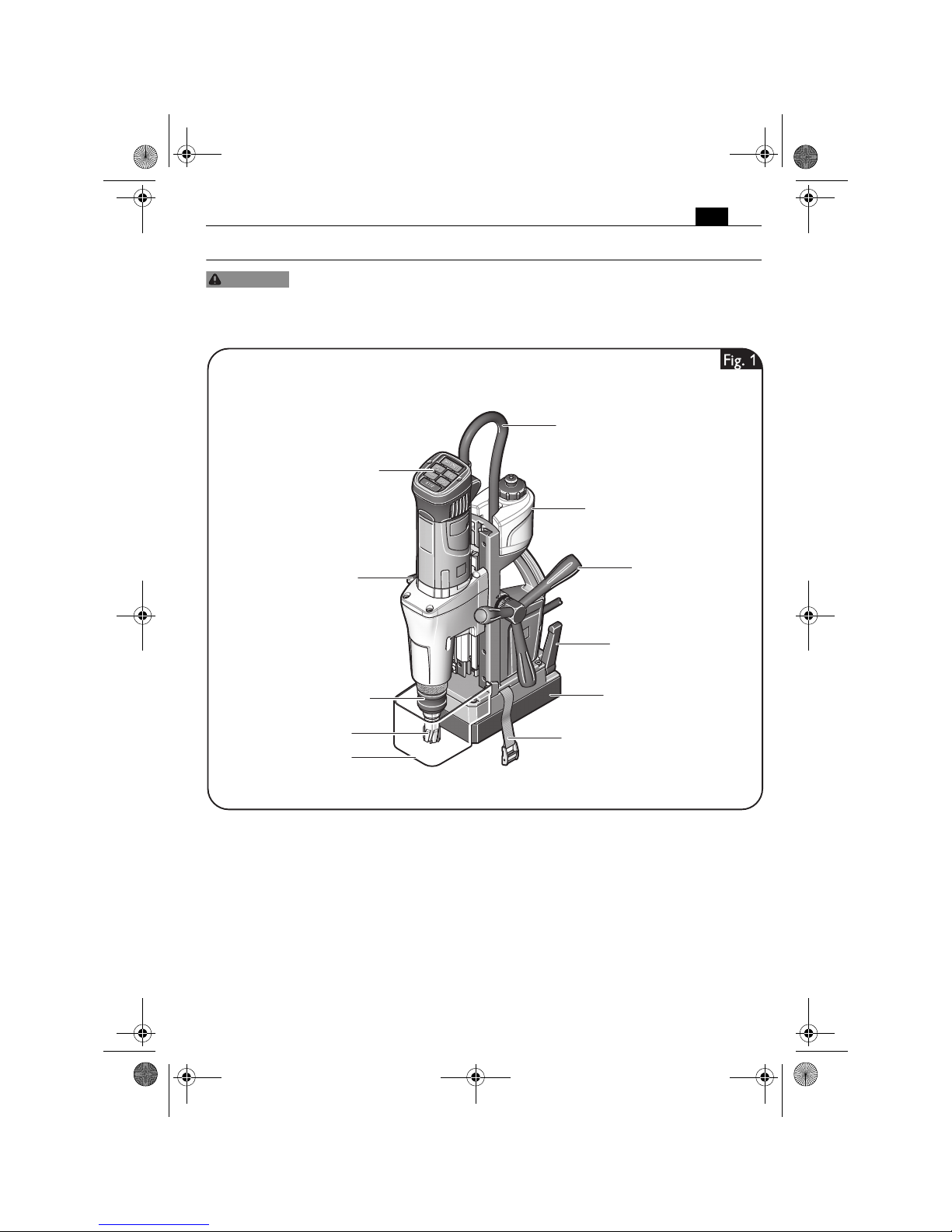
WARNING
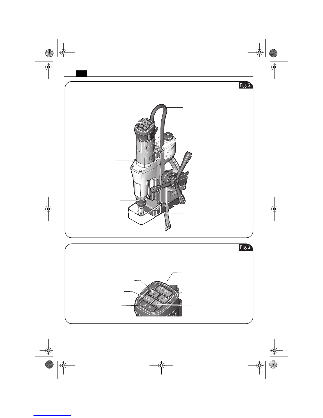
Application tool
Tool holder
Viseo Touch Pad
Drill-motor cable
Coolant container
Magnetic foot
Clamping lever
for fine adjustment
Clamping strap
JCM 200 QX, JCM 200 U, JCM 256 U
Gear switch
Chip guard
Spoke handle
OBJ_BUCH-0000000130-002.book Page 9 Monday, November 18, 2013 10:38 AM
10
en
Viseo Touch Pad
JCM 200 auto
Application tool
Drill-motor cable
Coolant container
Magnetic foot
Clamping strap
Gear switch
Chip guard
Spoke handle
Tool holder
Switches the magnet On/Off
Starts the drill motor
Rotation direction: clockwise
Speed reduction in steps
Starts the drill motor in inch mode
Rotation direction: anticlockwise
Stops the drill motor Speed increase in steps
OBJ_BUCH-0000000130-002.book Page 10 Monday, November 18, 2013 10:38 AM
11
en
Type JCM 200 QX JCM 200 U JCM 200 auto JCM 256 U
Order number 7 270 45 7 270 44 7 270 46 7 270 47
Current consumption 12.5 A 12.5 A 12.5 A 12.6 A
Power input 1200 W 1200 W 1200 W 1350 W
Output 600 W 600 W 600 W 650 W
No-load speed (right rotation)
1. Gear 260 /min 260 /min 260 /min 240 /min
2. Gear 520 /min 520 /min 520 /min 520 /min
No-load speed (left rotation)
1. Gear 185 /min 185 /min 185 /min 170 /min
2. Gear 370 /min 370 /min 370 /min 370 /min
Drilling capacity in steel - TCT
(core drill bit)
7/16 in – 2 in
12 mm – 50 mm
7/16 in – 2 in
12 mm – 50 mm
7/16 in – 2 in
12 mm – 50 mm
7/16 in – 2 5/8 in
12 mm – 65 mm
Drilling capacity in steel - high speed
steel (HSS) (core drill bit)
7/16 in – 1 5/8 in
12 mm – 40 mm
7/16 in – 1 5/8 in
12 mm – 40 mm
7/16 in – 1 5/8 in
12 mm – 40 mm
7/16 in – 1 3/16 in
12 mm – 45 mm
Drilling capacity in steel - high speed
steel (HSS) (twist drill bit)
5/8 in
16 mm
15/16 in
23 mm
15/16 in*
23 mm*
1 in
25 mm
Tapped hole 1/4 in – 5/8 in
M6 – M16
1/4 in – 5/8 in
M6 – M16
1/4 in* – 5/8 in*
M6* – M16*
1/4 in – 6/8 in
M6 – M20
Reamer diameter 5/8 in
16 mm
15/16 in
23 mm
15/16 in*
23 mm*
1 in
25 mm
Counterboring diameter 1 1/4 in
31 mm
2 in
50 mm
2 in*
50 mm*
2 in
50 mm
Weight according to EPTA-Procedure
01/2003
29.48 lbs
(13.4 kg)
31.02 lbs
(14.1 kg)
36.08 lbs
(16.4 kg)
35.86 lbs
(16.3 kg)
Class of protection /I /I /I /I
* Value applies for JCM 200 auto in manual machine operation
OBJ_BUCH-0000000130-002.book Page 11 Monday, November 18, 2013 10:38 AM
12
en
Assembly instructions.
Before mounting or replacing cutting tool or accessories, pull the power plug.
This preventive safety measure rules out the danger of injuries through accidental starting of the power tool.
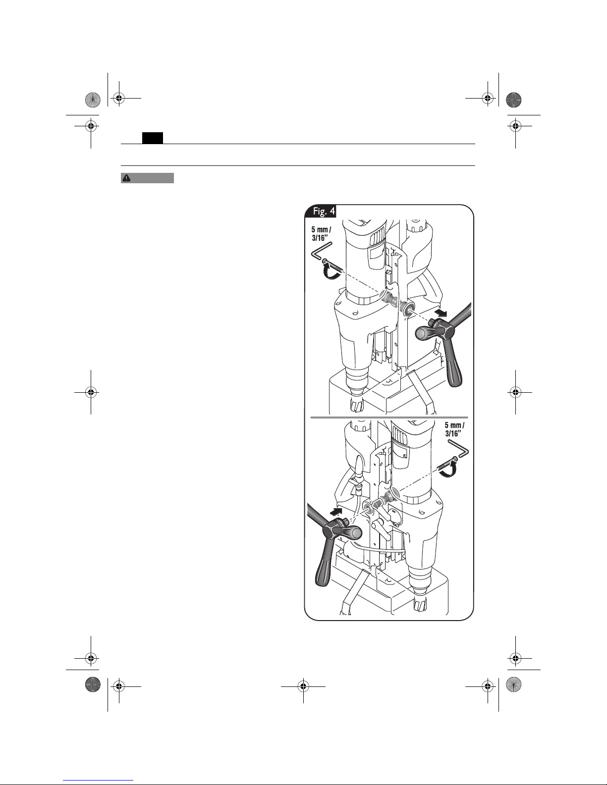
Mounting the spoke handle
(JCM 200 QX, JCM 200 U, JCM 256 U)
(figure 4).
The hub assembly can be mounted on either
side.
Loosen the screw using a hex key.
Remove the spoke handle.
WARNING
OBJ_BUCH-0000000130-002.book Page 12 Monday, November 18, 2013 10:38 AM
13
en
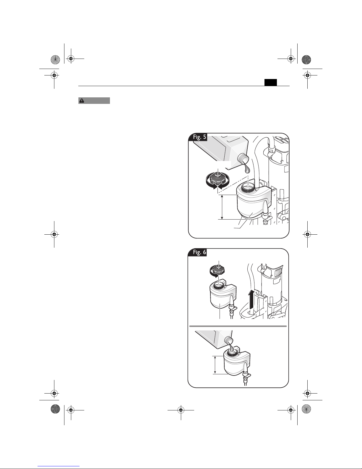
Filling the coolant container.
Prevent the flow of liquid along the cable into the socket outlet or into the core
drill unit, as this can lead to electric shock. Tie a bow in the cable near the plug,
so that any liquid can drip off.
Do not use the magnetic base drill unit if the cooling lubricant system is defective. Check for
proper seal against leaks and for cracks in the hoses. Prevent liquids from entering or penetrating electrical components.
Filling the mounted coolant container
(figure 5)
Unscrew the cap from the coolant container.
Fill in pump-feedable cooling lubricant, e.g.
Slugger cutting oil.
Screw the cap onto the coolant container
again.
Filling the dismounted coolant container
(figure 6)
Pull the empty coolant container out of the
drill stand housing of the magnetic core drill.
Unscrew the cap from the coolant container.
Fill in pump-feedable cooling lubricant, e.g.
Slugger cutting oil.
Screw the cap onto the coolant container
again.
Insert the filled coolant container into the
holder on the drill stand housing intended for
this purpose.
WARNING
Coolant container
Upper closing cap
max. 500 ml
max. 17 fl. OZ.
max. 500 ml
max. 17 fl. OZ.
Coolant container
Upper closing cap
OBJ_BUCH-0000000130-002.book Page 13 Monday, November 18, 2013 10:38 AM
14
en
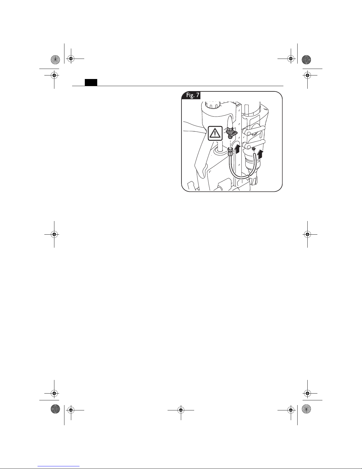
Mounting the coolant hose (figure 7).
Connect the coolant hose.
OBJ_BUCH-0000000130-002.book Page 14 Monday, November 18, 2013 10:38 AM
15
en
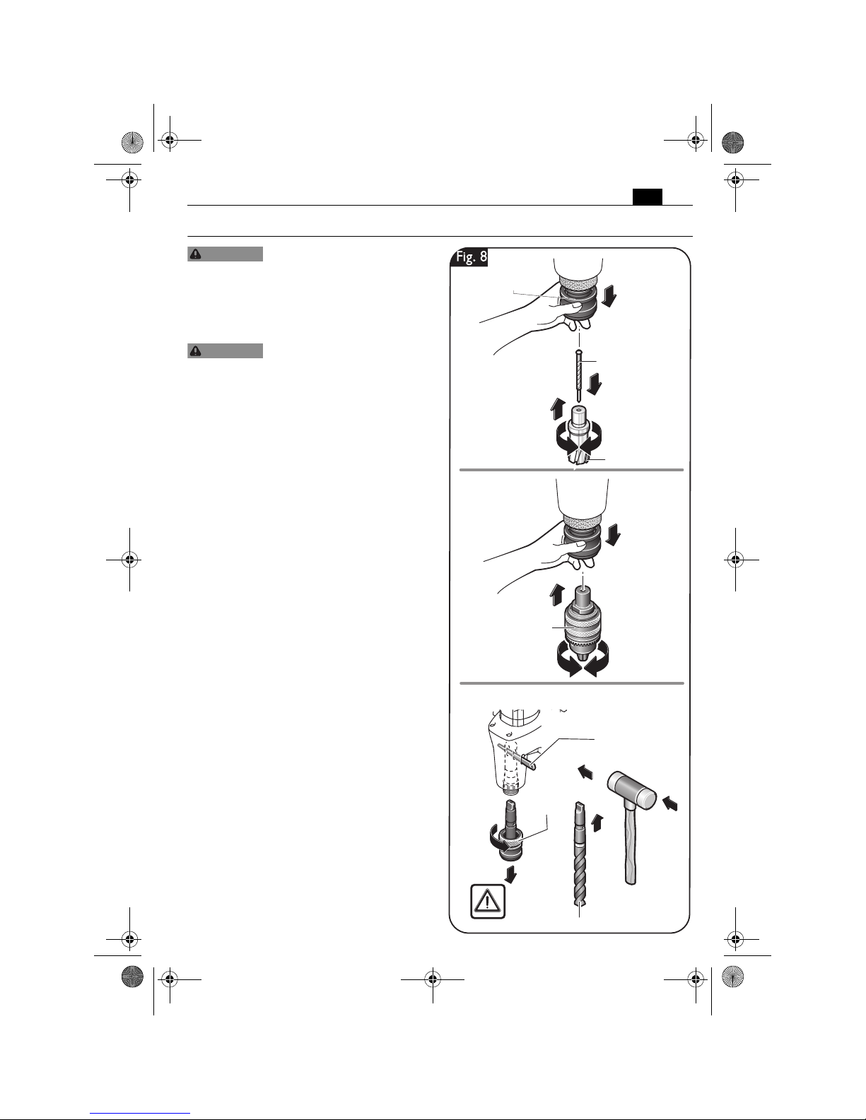
Changing the tool (figure 8).
Secure the power tool with the
safety strap supplied at all
times, especially for work carried out at elevated heights, when drilling horizontally or
above the head. If there is a power loss, or the
power plug is pulled out, the magnetic holding power is not maintained.
Before mounting or replacing
cutting tool or accessories,
pull the power plug. This preventive safety
measure rules out the danger of injuries
through accidental starting of the power tool.
Core drill bit
Insert the pilot pin into the cutter.
Pull the clamping sleeve of the tool holder
down and insert the core drill bit with the
centering pin into the tool holder.
Do not touch the sharp edges of the core drill
bit. Danger of injury.
Drill chuck
Pull the clamping sleeve of the tool holder
down and insert the drill chuck.
Drill bit
The knurled nut has a left-hand thread; turn
clockwise to release!
Loosen the knurled nut and remove the tool
holder by applying a hammer blow to the
positioned drift.
Clean the inside cone of the output shaft and
insert the drill bit.
WARNING
WARNING
MT 3
CM 3
Drill chuck
Drift
Drill bit
Clamping sleeve
JCM 200 U, JCM 200 auto, JCM 256 U
Knurled
nut
Centering pin
Core drill bit
OBJ_BUCH-0000000130-002.book Page 15 Monday, November 18, 2013 10:38 AM

16
en
Working instructions.
Secure the power tool with the safety strap supplied at all times, especially for
work carried out at elevated heights, when drilling horizontally or above the
head. If there is a power loss, or the power plug is pulled out, the magnetic holding power is
not maintained.
Fastening the safety strap (figure 9).
Fasten the machine securely around the
workpiece using the provided safety strap.
For switching the magnet ON
(figure 10).
Please make sure that the contact surfacefor the magnetic base is level, clean and
rust-free. Remove any varnish or primer.
When working, always use the magnetic foot;
pay attention that the magnetic holding
power is sufficient:
Press the Magnet button to start the machine.
– When the green Magnet button on the
control panel lights up permanently, the
magnetic holding power is sufficient and
the power tool can be operated with man-
ual or automatic feed.
– When the Magnet button on the control
panel flashes green, the magnetic holding
power possibly is insufficient and the
power tool must be operated manually
with reduced feed. In this case, the JCM
200 auto may not be operated in automatic
mode.
When working on non-metal materials, suitable clamping devices, such as the vacuum
plate or pipe-drilling fixture, which are available as accessories, must be used.
When working on steel materials with a
material thickness less than 12 mm, the workpiece must be enforced with an additional
steel plate in order to ensure the magnetic
holding power.
The magnetic foot is monitored by means of
a power sensor. If the magnetic foot is defective, the drill motor will not start.
WARNING
Clamping strap
Switches the magnet On/Off
=
=
JCM 200 QX, JCM 200 U, JCM 256 U
JCM 200 auto
OBJ_BUCH-0000000130-002.book Page 16 Monday, November 18, 2013 10:38 AM

17
en
Adjusting the stroke range (figure 11).
Hold the power tool firmly
with one hand when releasing
the two fastening levers.
To move the fastening levers over each other,
pull a fastening lever outward and then turn
the fastening lever in 45° steps.
Loosen both fastening levers with the other
hand.
Adjust the desired stroke range.
Tighten both fastening levers again.
Adjusting the working position
(JCM 256 U) (figure 12).
Release the fine-adjustment clamping lever.
Adjust the desired position. The drill stand
can be moved toward the front or rear on the
magnetic foot, and can be turned toward the
right and left.
Tighten the clamping lever again.
CAUTION
Fig.12
OBJ_BUCH-0000000130-002.book Page 17 Monday, November 18, 2013 10:38 AM

18
en
Activating and deactivating the coolant-lubricant flow (figure 13).
To activate the cooling-lubricant flow,
open the ventilation first and then turn
the flow valve to the position shown.
For switching off or when working
overhead, deactivate the cooling-lubricant flow. Shut the ventilation and turn
the flow valve to the position shown.
When working overhead, use a cooling-lubricant paste from Slugger.
2.
1.
Coolinglubricant paste
Ventilation
Fig.13
OBJ_BUCH-0000000130-002.book Page 18 Monday, November 18, 2013 10:38 AM

19
en
Switching the gear setting
(figure 14).
With the gear switch, you can select the
speed and thus the torque.
Adjust the gear setting only when the
machine is at a complete stop or when the
motor is running down.
Set the switch to gear 1 to work at low speed
with high torque. This setting is suitable for
drilling with large drill bit diameters and for
tapping.
Set the switch to gear 2 to work at h igh spe ed
with low torque. This setting is suitable for
drilling with small drill bit diameters.
Fig.14
Drilling capacity in
steel - TCT
(core drill bit)
Drilling capacity
in steel - high speed
steel (HSS)
(core drill bit)
Drilling capacity in
steel - high speed
steel (HSS)
(twist drill bit)
Tapped hole
JCM 200 U,
JCM 200 QX,
JCM 200 auto
1. Gear 27 – 50 mm
1 1/16 in – 2 in
21 – 40 mm
3/16 in – 1 5/8 in
16 mm – 23 mm
5/8 in – 7/8 in
M6 – M16
1/4 in – 5/8 in
JCM 256 U 1. Gear 27 – 65 mm
1 1/16 in – 2 5/8 in
21 – 45 mm
1 1/16 in – 1 3/16 in
16 – 25 mm
5/8 in – 1 in
M6 – M20
1/4 in – 6/8 in
JCM 200 U,
JCM 200 QX,
JCM 200 auto
2. Gear 12 – 26 mm
7/16 in – 1 1/16in
12 – 20 mm
7/16 in – 3/4 in
1,5 – 15 mm
1/16 in – 5/8 in
-
JCM 256 U 2. Gear 12 – 26 mm
7/16 in – 1 1/16in
12 – 20 mm
7/16 in – 3/4 in
1,5 – 15 mm
1/16 in – 5/8 in
-
Max. diameter
for reaming
Max. diameter for
counterboring
JCM 200 QX 1. Gear ≤ 16 mm
≤ 5/8 in
≤ 31 mm
≤ 1 3/4 in
JCM 200 U,
JCM 200 auto
1. Gear ≤ 23 mm
≤ 7/8 in
≤ 50 mm
≤ 2 in
JCM 256 U 1. Gear ≤ 25 mm
≤ 1 in
≤ 50 mm
≤ 2 in
OBJ_BUCH-0000000130-002.book Page 19 Monday, November 18, 2013 10:38 AM

20
en
Starting and stopping the drill motor
(figure 15).
To start the drill motor with clockwise rotation, press the button with the „ “ symbol.
The drill motor starts with the highest speed.
The last set speed is automatically stored
(Memory Function). To start the power tool
with the last set speed, press and hold the
button with the symbol, and then press
the button with the symbol.
To lower the speed, press the „ “ symbol.
To increase the speed, press the „ “ symbol.
To stop the drill motor, press the „ “
symbol.
Do not stop the drill motor during the drilling
procedure.
To start the drill motor with counterclockwise rotation, press the button with the
„ “ symbol. The drill motor will run as
long as the button is pressed.
When the power supply is disconnected
while the drill motor is running, a protective
circuit prevents automatic restarting of the
drill motor. Restart the drill motor again.
In case of overload, the drill motor automatically stops and must be restarted again.
100l%
85
l%
75
l%
60
l%
50
l%
100
l%
85
l%
75
l%
60
l%
50
l%
Memory Function
Fig.15
OBJ_BUCH-0000000130-002.book Page 20 Monday, November 18, 2013 10:38 AM

21
en
Feed (JCM 200 QX, JCM 200 U,
JCM 256 U) (figure 16).
To generate feed, turn the spoke handle manually while the drill motor is switched on.
The scale can be used with “inch” or with
“cm” graduation.
Feed (JCM 200 auto)
(figure 17).
Automatic feed
Set the spoke handles outward.
Press the button with the „ “ symbol.
The application tool starts to rotate and
moves in the direction of the workpiece. The
power tool is equipped with a bit breakthrough detection. Upon completion of the
drilling procedure, the power tool detects the
break-through, and the drill motor automatically returns to the starting position. The drill
motor does not switch off until in the starting
position.
Do not rotate the spoke handle during automatic feed operation.
Do not use the automatic feed when drilling,
countersinking, tapping and reaming.
Manual feed
Leave the spoke handle in the inner (upright)
position.
To generate feed, turn the spoke handle manually while the drill motor is switched on.
cm
inch
Fig.16
1.
3.
2.
Fig.17
OBJ_BUCH-0000000130-002.book Page 21 Monday, November 18, 2013 10:38 AM

22
en
Feed without spoke handle
(JCM 200 auto) (Fig. 18).
Depending on the application, the feed can
also be actuated from the left-hand side. For
this, apply the drive socket.
To generate feed, turn the drive socket manually while the drill motor is switched on.
Instructions for core drilling.
Do not stop the drill motor during the drilling
procedure.
Only remove the cutting tool from the hole
while the motor is running.
If the carbide tipped cutter should remain
stuck in the material, stop the drill motor and
carefully turn the carbide tipped cutter out
clockwise.
After each drilling operation, remove the
chips and the slug.
Do not touch the chips with your bare
hand. Always use a chip hook.
Danger of burns! The surface
of the magnet can reach high
temperatures. Do not touch the magnet with
your bare hands.
For core drilling in layered material, use a suitable Slugger ID cutter.
When changing a cutting tool, pay attention
not to damage the cutting edges.
30 mm/
1 3/16 in
Fig.18
CAUTION
OBJ_BUCH-0000000130-002.book Page 22 Monday, November 18, 2013 10:38 AM

23
en
Repair and customer service.
Before mounting or replacing cutting tool or accessories, pull the power plug.
This preventive safety measure rules out the danger of injuries through accidental starting of the power tool.
Exchangeable parts
If required, you can change the following
parts yourself:
application tools, coolant container
Drill-motor guide (figure 19).
After several hours of operation, the play in
the drill-motor guide can increase. As a consequence, the drill motor can glide alongside
the drill-motor guide. In automatic machine
operation, this can lead to a malfunction of
the automatic reversing feature. In this case,
retighten all fastening screws of the drillmotor guide correspondingly so that the drill
motor can easily be moved manually, yet does
not glide by itself.
Service.
Have maintenance carried out
only through qualified personnel. Incorrectly mounted cables and components can cause serious injuries. Have the
required service carried out only through an
authorized Slugger repair facility.
When replacing the power
tool's protective cable bushing
or cord between the drill stand and drill
motor is required, this must be carried out by
Slugger or by an authorized Slugger Service
Agent, in order to avoid hazardous situations.
The current spare parts list for this power
tool can be found in the Internet at
www.fein.com.
Cleaning.
Prior to any cleaning or main-
tenance, disconnect the power
tool from the power supply in order to avoid
accidents.
When using in environments
with conductive dust in the air,
such as when cutting metals, this dust can
settle in the interior of the power tool. This
can impair the total insulation of the power
tool. Therefore, regularly blow out the interior
of the power tool from outside via the ventilation openings with dry, oil-free compressed
air; always wear eye protection when doing
this. For additional protection, connect a
residual current device (RCD) on the line side.
WARNING
2,5 mm
3/32 in
Fig.19
Drill-motor
guide
Fastening
screws
WARNING
CAUTION
WARNING
WARNING
OBJ_BUCH-0000000130-002.book Page 23 Monday, November 18, 2013 10:38 AM

24
en
Do not attempt to clean
clogged or dirty ventilation
openings of the power tool with pointed
metal objects; use nonmetal tools or objects
if necessary.
Do not use cleaning agents
and solvents that can cause
damage to plastic parts. These include: Gas-
oline, carbon-tetrachloride, chloric solvents,
ammonia and domestic cleaning agents that
contain ammonia.
Cooling-lubricant system.
Flush the cooling-lubricant system with
water, clean and drain it completely when not
using the machine for periods longer than
two weeks.
Warranty and liability.
The warranty for the product is valid in accordance with the legal regulations in the country
where it is marketed.
Environmental protection, disposal.
Sort scrapped power tools and accessories for environmental-friendly recycling. For further
information, please contact your specialist shop.
CAUTION
CAUTION
OBJ_BUCH-0000000130-002.book Page 24 Monday, November 18, 2013 10:38 AM

25
en
Provided accessories (figure 20).
Drift
Power tool
carrying case
JCM 256 U
JCM 200 QX
JCM 200 U
JCM 200 auto
JCM 200 U
JCM 200 auto
JCM 256 U
JCM 200 U
JCM 200 auto
JCM 256 U
Fig.20
Chip hook
Clamping strap
Chip guard
Chip guard
Centering pin
Tool holder
OBJ_BUCH-0000000130-002.book Page 25 Monday, November 18, 2013 10:38 AM

26
es
es
Para su seguridad.
Lea íntegramente estas
advertencias de peligro e
instrucciones. En caso de no atenerse a las
advertencias de seguridad siguientes, ello
puede ocasionar una descarga eléctrica, un
incendio y/o lesión grave.
Guardar todas las advertencias de peligro e
instrucciones para futuras consultas.
No utilice esta herramienta eléctrica sin
haber leído antes con detenimiento y
haber entendido por completo estas instrucciones de uso, inclusive las ilustraciones,
especificaciones, reglas de seguridad, así
como las indicaciones identificadas con PELIGRO, ADVERTENCIA y PRECAUCIÓN.
Solamente use esta herramienta eléctrica
para realizar los trabajos que el fabricante ha
previsto para la misma. Únicamente utilice
los útiles de corte y accesorios aprobados
por el fabricante.
Observe también las respectivas prescripciones contra accidentes de trabajo vigentes en
su país.
En caso de no atenerse a las instrucciones de
seguridad mencionadas en la documentación
previamente citada, ello puede provocar una
electrocución, incendio y/o lesión grave.
Guarde estas instrucciones de uso para posteriores consultas y entrégueselas al usuario en
caso de prestar o vender la máquina.
GUARDAR ESTAS INSTRUCCIONES EN
UN LUGAR SEGURO.
El término “herramienta eléctrica” empleado
en las siguientes instrucciones de seguridad
se refiere a herramientas eléctricas de
conexión a la red (con línea) y a herramientas eléctricas accionadas por batería (o sea,
sin línea).
Instrucciones generales de
seguridad.
1) Seguridad en el puesto de trabajo
a)Mantenga limpio y bien iluminado su
puesto de trabajo. El desorden y una ilu-
minación deficiente en las áreas de trabajo pueden provocar accidentes.
b) No utilice la herramienta eléctrica en un
entorno con peligro de explosión, en el
que se encuentren combustibles líquidos, gases o material en polvo. Las
herramientas eléctricas producen chispas que pueden llegar a inflamar los
materiales en polvo o vapores.
c) Mantenga alejados a los niños y otras
personas de su puesto de trabajo al
emplear la herramienta eléctrica. Una
distracción le puede hacer perder el
control sobre el aparato.
2) Seguridad eléctrica
a)La clavija del aparato debe correspon-
der al enchufe utilizado. No es admisible
modificar la clavija en forma alguna. No
emplear adaptadores en aparatos dotados con una toma de tierra. Las clavijas
sin modificar adecuadas a los respectivos enchufes reducen el riesgo de una
descarga electrica.
b)Evite que su cuerpo toque partes conec-
tadas a tierra como tuberías, radiadores, cocinas y refrigeradores. El riesgo
a quedar expuesto a una sacudida eléctrica es mayor si su cuerpo tiene contacto con tierra.
c) No exponga las herramientas eléctricas
a la lluvia y evite que penetren líquidos
en su interior. Existe el peligro de recibir
una descarga eléctrica si penetran ciertos líquidos en la herramienta eléctrica.
d)No utilice la línea para transportar o col-
gar el aparato, ni tire de ella para sacar
la clavija de la toma de corriente. Mantenga la línea alejada del calor, aceite,
esquinas cortantes o piezas móviles. Las
líneas dañadas o enredadas pueden provocar una descarga eléctrica.
e) Al trabajar con la herramienta eléctrica a
la intemperie utilice solamente extensiones homologadas para su uso en exteriores. La utilización de una extensión
adecuada para su uso en exteriores
reduce el riesgo de una descarga eléctrica.
f) Si fuese imprescindible utilizar la herra-
mienta eléctrica en un entorno húmedo,
es necesario conectarla a través de un
fusible diferencial. La aplicación de un
fusible diferencial reduce el riesgo a
exponerse a una descarga eléctrica.
ADVERTENCIA
OBJ_BUCH-0000000130-002.book Page 26 Monday, November 18, 2013 10:38 AM

27
es
3) Seguridad de personas
a)Esté atento a lo que hace y emplee la
herramienta eléctrica con prudencia. No
utilice la herramienta eléctrica si estuviese cansado, ni tampoco después de
haber consumido alcohol, drogas o
medicamentos. El no estar atento
durante el uso de una herramienta eléctrica puede provocarle serias lesiones.
b) Utilice un equipo de protección y en todo
caso unas gafas de protección. El riesgo
a lesionarse se reduce considerablemente si, dependiendo del tipo y la aplicación de la herramienta eléctrica
empleada, se utiliza un equipo de protección adecuado como una mascarilla
cubrepolvo, zapatos de seguridad antideslizantes, cubierta, o protectores
auditivos.
c) Evite una puesta en marcha fortuita del
aparato. Asegúrese de que el aparato
esté apagado antes de conectarlo al
enchufe. Si transporta el aparato suje-
tándolo por el switch, o si conecta la clavija al enchufe con el aparato encendido,
ello puede dar lugar a un accidente.
d)Retire las herramientas de ajuste o lla-
ves fijas antes de conectar la herramienta eléctrica. Una herramienta o
llave colocada en una pieza rotante
puede producir lesiones al ponerse a
funcionar.
e) Sea precavido. Trabaje sobre una base
firme y mantenga el equilibrio en todo
momento. Ello le permitirá controlar
mejor la herramienta eléctrica en caso
de presentarse una situación inesperada.
f) Lleve puesta una ropa de trabajo ade-
cuada. No utilice ropa amplia ni joyas.
Mantenga su pelo, ropa y guantes alejados de las piezas móviles. La ropa
suelta, las joyas y el pelo largo se pueden
enganchar con las piezas en movimiento.
g)Siempre que sea posible utilizar unos
equipos de aspiración o captación de
polvo, asegúrese de que éstos estén
apropiadamente conectados y que sean
utilizados correctamente. El empleo de
estos equipos reduce los riesgos derivados del polvo.
4) Trato y uso cuidadoso de herramientas
eléctricas
a) No sobrecargue el aparato. Use la herra-
mienta prevista para el trabajo a realizar. Con la herramienta adecuada podrá
trabajar mejor y más seguro dentro del
margen de potencia indicado.
b)No utilice herramientas con un switch
defectuoso. Las herramientas que no se
puedan encender o apagar son peligrosas y deben hacerse reparar.
c) Saque la clavija de la red antes de rea-
lizar un ajuste en el aparato, cambiar de
accesorio o al guardar el aparato. Esta
medida preventiva reduce el riesgo a
encender accidentalmente el aparato.
d)Guarde las herramientas fuera del
alcance de los niños y de las personas
que no estén familiarizadas con su uso.
Las herramientas utilizadas por personas inexpertas son peligrosas.
e) Cuide sus herramientas eléctricas con
esmero. Controle si funcionan correctamente, sin atascarse, las partes móviles
del aparato, y si existen partes rotas o
deterioradas que pudieran afectar al
funcionamiento de la herramienta. Si la
herramienta eléctrica estuviese defectuosa haga repararla antes de volver a
utilizarla. Muchos de los accidentes se
deben a aparatos con un mantenimiento
deficiente.
f) Mantenga los útiles de corte limpios y
afilados. Los útiles de corte mantenidos
correctamente se dejan guiar y controlar mejor.
g)Utilice herramientas eléctricas, acceso-
rios, útiles, etc. de acuerdo a estas instrucciones y en la manera indicada
específicamente para este aparato.
Considere en ello las condiciones de trabajo y la tarea a realizar. El uso de
herramientas eléctricas para trabajos
diferentes de aquellos para los que han
sido concebidas puede resultar peligroso.
5) Servicio
a)Únicamente haga reparar su herra-
mienta eléctrica por un profesional,
empleando exclusivamente refacciones
originales. Solamente así se mantiene la
seguridad de la herramienta eléctrica.
OBJ_BUCH-0000000130-002.book Page 27 Monday, November 18, 2013 10:38 AM

28
es
Instrucciones de seguridad especiales.
Utilice un equipo de protección. Dependiendo
del trabajo a realizar use una protección para
la cara o lentes de protección. Utilice un protector acústico. Los lentes de protección
deberán ser apropiados para protegerle de los
fragmentos que pudieran salir despedidos al
trabajar. La exposición permanente al ruido
puede provocar sordera.
Cambie inmediatamente una manguera de
protección del cable dañada. Una manguera
de protección del cable defectuosa puede
provocar un sobrecalentamiento de la máquina y causar una desconexión de emergencia.
Antes de comenzar a trabajar monte en la
máquina la guarda contra contacto.
Si en el trabajo a realizar existiese el peligro
de que pueda caerse la herramienta eléctrica,
asegure ésta con la cinta tensora suministrada, especialmente al trabajar a cierta
altura, en elementos verticales, o al trabajar
por encima de la cabeza. En caso de un corte
del fluido eléctrico o al sacar el enchufe de
red, se anula la fuerza magnética de sujeción.
No utilice el depósito de refrigerante si
tuviese que mantener el aparato en posición
vertical o por encima de la cabeza al trabajar
las piezas. Emplee un spray de refrigeración
en estos casos. La penetración de líquido en la
herramienta eléctrica puede ocasionar una
descarga eléctrica.
Evite el contacto con el núcleo de perforación
que el perno de centrado expulsa automáticamente al finalizar el trabajo. Al ser golpeado
por el núcleo, que además puede estar muy
caliente, puede llegar a accidentarse.
Únicamente conecte la herramienta eléctrica
a tomas de corriente provistas de un contacto
de protección reglamentario. Solamente utilice cables de conexión en perfectas condiciones, y unas extensiones provistas de un
contacto de protección sometidas a una inspección periódica. Un cable de protección
defectuoso puede provocar una descarga
eléctrica.
Para no lesionarse, siempre mantenga las
manos, ropa, etc. alejadas de las virutas en
rotación. Las virutas pueden lesionarle. Siem-
pre use la protección contra virutas.
No intente retirar el útil mientras éste esté
girando todavía. Podría lesionarse grave-
mente.
Sujete el aparato por las áreas de agarre aisladas al realizar trabajos en los que el útil
pueda tocar conductores eléctricos ocultos o
el propio cable del aparato. El contacto con
conductores bajo tensión puede hacer que las
partes metálicas del aparato le provoquen una
descarga eléctrica.
Preste atención a los conductores eléctricos y
a las tuberías de agua y gas ocultas. Antes de
comenzar a trabajar explore la zona de trabajo, p. ej., con un detector de metales.
No trabaje materiales que contengan
amianto. El amianto es cancerígeno.
Esta prohibido fijar rótulos o señales a la
herramienta eléctrica con tornillos o remaches. Un aislamiento dañado no le protege de
una electrocución. Emplee etiquetas autoadhesivas.
No use accesorios que no hayan sido especialmente desarrollados u homologados por el
fabricante de la herramienta eléctrica. El
mero hecho de que sea montable un accesorio en su herramienta eléctrica no es garantía
de que su funcionamiento sea seguro.
Limpie periódicamente las rejillas de refrigeración de la herramienta eléctrica empleando
herramientas que no sean de metal. El venti-
lador del motor aspira polvo hacia el interior
de la carcasa. En caso de acumularse polvo de
metal en exceso, ello puede provocar al usuario una descarga eléctrica.
Antes de la puesta en marcha inspeccione si
están dañados el cable de red y el enchufe.
Recomendación: Siempre opere la herramienta eléctrica a través de un interruptor
diferencial (RCD) con una corriente de disparo máxima de 30 mA.
OBJ_BUCH-0000000130-002.book Page 28 Monday, November 18, 2013 10:38 AM

29
es
Tratamiento de materiales en polvo peligrosos.
Al trabajar con herramien-
tas, p. ej., al lijar, pulir,
serrar o realizar otros trabajos con arranque
de material, los polvos que se producen pueden ser nocivos para la salud, autoinflamables o explosivos.
El contacto o inspiración de ciertos materiales
en polvo puede provocar en el usuario, o en
las personas circundantes, reacciones alérgicas
y/o enfermedades respiratorias, cáncer, daños
congénitos u otros trastornos reproductivos.
A continuación, indicamos algunos de estos
materiales junto con los productos químicos
que contienen, cuyo polvo producido al trabajar, puede ser nocivo para la salud:
– Amianto y materiales que contengan
amianto;
– Pinturas que contengan plomo, ciertos
tipos de madera como, p. ej., haya, encino
y roble;
– Minerales y metales;
– Partículas de sílice de ladrillo, concreto y
demás materiales que contengan mineral;
– Los solventes que contienen ciertas pintu-
ras;
– Arsénico, cromo y otros conservadores de
la madera;
– Materiales para combatir parásitos en cas-
cos de botes o barcos;
– Polvos de acero inoxidable, de metales y
de metales no férricos.
Para que la exposición a estos materiales sea
mínima:
– Utilice un equipo de aspiración apropiado
para el polvo producido.
– Use equipos de protección personal como,
por ejemplo, una mascarilla guardapolvo
con un filtro de la clase P2.
– Observe que esté bien ventilado el puesto
de trabajo.
El riesgo derivado de la inspiración de material en polvo depende de la frecuencia con la
que se trabajen estos materiales. Los materiales que contengan amianto solamente deberán ser procesados por especialistas.
El polvo de madera y el de
aleaciones ligeras puede
autoinflamarse o provocar una explosión.
Si en el saco filtrante o en el filtro del aspirador, el polvo caliente producido al lijar se
mezcla con restos de pintura, poliuretano, u
otras materias químicas, puede que ésta se
autoincendie bajo condiciones desfavorables
como, p. ej., el salto de chispas al lijar metales,
la exposición permanente y directa al sol, o
una temperatura ambiente elevada. Para prevenir esta situación:
– Evite que se sobrecalienten la pieza de tra-
bajo y la herramienta eléctrica.
– Vacíe el depósito de polvo con suficiente
antelación.
– Observe las instrucciones de elaboración
del fabricante del material.
– Considere las prescripciones sobre los
materiales a trabajar.
Emisión de ruidos (Indicación de dos cifras según ISO 4871)
ADVERTENCIA
ATE NC I Ó N
Emisión de ruido JCM 200 QX JCM 200 U JCM 200 auto JCM 256 U
Nivel de de presión sonora
L
pA
(re
20 μPa), medido con filtro A en el
puesto de trabajo, en decibelios 82.4 82.4 82.4 82.4
Inseguridad
K
pA
, en decibelios 3 3 3 3
Nivel de potencia acústica
L
wA
(re
1 pW), medido con filtro A, en
decibelios 93.4 93.4 93.4 93.4
Inseguridad
K
wA
, en decibelios 3 3 3 3
Valor pico del nivel de presión
sonora
L
pCpeak
medido con filtro C
en el puesto de trabajo, en decibelios 97.0 97.0 97.0 97.0
OBJ_BUCH-0000000130-002.book Page 29 Monday, November 18, 2013 10:38 AM

30
es
Extensiones.
En caso de utilizar una
extensión, la longitud y la
sección de la línea deberá ser la correcta
para el trabajo a realizar para evitar una caída de tensión en la línea, una reducción de la
potencia, y el sobrecalentamiento de la herramienta eléctrica. De lo contrario, se presen-
tan peligros de origen eléctrico en la
extensión y en la herramienta eléctrica, además de reducirse sus prestaciones.
Longitudes y secciones del cable recomendadas para las extensiones al trabajar con una
tensión alterna monofásica de 120 V,
teniendo conectado solamente un JCM 200
QX, JCM 200 U, JCM 200 auto, JCM 256 U:
Utilización reglamentaria de la herramienta eléctrica:
Unidad de taladrado para taladrar con coronas
perforadoras y brocas, para rimar, avellanar y
roscar en lugares cubiertos, materiales con
superficies magnetizables con los útiles y
accesorios autorizados por Slugger.
Alimentación de la herramienta eléctrica con un grupo electrógeno.
Esta herramienta eléctrica es apta además
para ser utilizada con grupos electrógenos de alterna siempre que dispongan de suficiente potencia y cumplan los requisitos
según norma ISO 8528 para la clase de ejecución G2. Deberá prestarse especial atención a
no sobrepasar el coeficiente de distorsión
máximo del 10 % establecido en dicha norma.
En caso de duda consulte los datos del grupo
utilizado por Ud.
Esta prohibido conectar la
herramienta eléctrica a
generadores de corriente cuya tensión en
vacío sea superior a la tensión indicada en la
placa de características de la herramienta eléctrica.
Inseguridad
K
pCpeak
, en decibelios 3 3 3 3
Promedio de vibraciones (taladrado con coronas)
– m/s
2
– ft/s
2
< 2.5
8.3
< 2.5
8.3
< 2.5
8.3
< 2.5
8.3
Inseguridad
K
, en
– m/s
2
– ft/s
2
1.5
4.9
1.5
4.9
1.5
4.9
1.5
4.9
OBSERVACIÓN: la suma de los valores emitidos medidos, considerando la inseguridad respectiva, representa el límite superior que puede alcanzarse en las mediciones.
¡Utilizar unos protectores acústicos!
Valores de medición determinados según normativa del producto pertinente.
Emisión de ruido JCM 200 QX JCM 200 U JCM 200 auto JCM 256 U
ADVERTENCIA
Longitud de la línea
en pies
Longitud de la línea
en m
≤ 100 100
–200
200
–300
≤ 30 30
– 6060–100
Calibre A.W.G. del
cable, mín.
Sección del cable en
mm
2
, mín.
16 14 12 1.5 2.5 4
ADVERTENCIA
OBJ_BUCH-0000000130-002.book Page 30 Monday, November 18, 2013 10:38 AM

31
es
Simbología.
Símbolo Definición
Es imprescindible leer los documentos que se adjuntan, como las instrucciones de servicio y las instrucciones generales de seguridad.
¡Seguir las instrucciones indicadas al margen!
¡Seguir las instrucciones indicadas al margen!
Antes de realizar el paso de trabajo descrito, sacar el enchufe de la red. En
caso contrario, podría accidentarse al ponerse en marcha fortuitamente la
herramienta eléctrica.
Al trabajar protegerse los ojos.
Al trabajar utilizar un protector acústico.
No tocar las piezas en rotación de la herramienta eléctrica.
Este símbolo confirma que este producto ha sido certificado en USA y
Canadá.
Este símbolo advierte sobre una situación peligrosa inminente. Un comportamiento incorrecto puede dar lugar a una lesión grave o incluso mortal.
Este símbolo advierte sobre una situación peligrosa que puede comportar
lesiones graves o mortales.
Este símbolo advierte sobre una situación peligrosa en la que pudiera
lesionarse.
Acumular por separado las herramientas eléctricas y demás productos
electrotécnicos y eléctricos inservibles y someterlos a un reciclaje ecológico.
Baja velocidad
Alta velocidad
Fuerza de sujeción magnética, suficiente
Fuerza de sujeción magnética, insuficiente
Arranque del motor de taladrar. Giro a derechas
Arranque del motor de taladrar con pulsador. Giro a izquierdas
Reducción escalonada de la velocidad
Aumento escalonado de la velocidad
Detención del motor
PELIGRO
ADVERTENCIA
ATE NC I Ó N
OBJ_BUCH-0000000130-002.book Page 31 Monday, November 18, 2013 10:38 AM

32
es
Conexión/desconexión del imán
* Valor válido para JCM 200 auto en modo de operación manual
Símbolo Definición
Símbolo Unidad nacional Definición
n
0
rpm; /min; min-1; r/min Revoluciones en vacío
P
W Unidad de medida de la potencia
° Unidad de medida del ángulo
U V Unidad de medida de la tensión eléctrica
f Hz Unidad de medida de la frecuencia
I
A Unidad de medida de la intensidad
m
lbs Unidad de medida de la masa
l ft, in Unidad de medida para la longitud, ancho, altura, pro-
fundidad, diámetro o roscas
Ø ft, in Diámetro de una pieza redonda
m, s, kg, A, mm, V, W,
Hz, N, °C, dB, min, m/s
2
Unidades básicas y unidades derivadas del sistema
internacional de unidades SI.
OBJ_BUCH-0000000130-002.book Page 32 Monday, November 18, 2013 10:38 AM

33
es
Descripción técnica y especificaciones.
Saque la clavija del enchufe antes de montar o cambiar los útiles y accesorios. Esta medida de seguridad preventiva evita los accidentes que pudieran
presentarse en caso de una puesta en marcha involuntaria.
El material de serie suministrado con su herramienta eléctrica puede que no corresponda en
su totalidad al material descrito o mostrado en estas instrucciones de servicio.
ADVERTENCIA
Útil
Viseo Touch Pad
Línea del motor de taladrar
Depósito de
refrigerante
Base magnética
Palanca de bloqueo
de ajuste fino
Cinta tensora
JCM 200 QX, JCM 200 U, JCM 256 U
Selector de
velocidad
Palanca
Guarda contra virutas
OBJ_BUCH-0000000130-002.book Page 33 Monday, November 18, 2013 10:38 AM

34
es
Viseo Touch Pad
JCM 200 auto
Línea del motor de taladrar
Útil
Depósito de
refrigerante
Base magnética
Cinta tensora
Selector de
velocidad
Palanca
Guarda contra virutas
Conexión y desconexión
el imán
Arranque del motor de taladrar.
Sentido de giro a derechas
Reducción escalonada de
la velocidad
Arranque del motor de taladrar
con pulsador.
Sentido de giro a izquierdas
Detención del motor
de taladrar
Aumento escalonado de
la velocidad
OBJ_BUCH-0000000130-002.book Page 34 Monday, November 18, 2013 10:38 AM

35
es
Tipo JCM 200 QX JCM 200 U JCM 200 auto JCM 256 U
Nº de referencia 7 270 45 7 270 44 7 270 46 7 270 47
Corriente absorbida 12.5 A 12.5 A 12.5 A 12.6 A
Potencia absorbida 1200 W 1200 W 1200 W 1350 W
Potencia útil 600 W 600 W 600 W 650 W
Revoluciones en vacío (giro a derechas)
1ª velocidad 260 rpm 260 rpm 260 rpm 240 rpm
2ª velocidad 520 rpm 520 rpm 520 rpm 520 rpm
Revoluciones en vacío (giro a izquierdas)
1ª velocidad 185 rpm 185 rpm 185 rpm 170 rpm
2ª velocidad 370 rpm 370 rpm 370 rpm 370 rpm
Diámetro de taladro en acero - metal
duro (corona perforadora)
7/16 in – 2 in
12 mm – 50 mm
7/16 in – 2 in
12 mm – 50 mm
7/16 in – 2 in
12 mm – 50 mm
7/16 in – 2 5/8 in
12 mm – 65 mm
Diámetro de taladro en acero - metal
duro (corona perforadora)
7/16 in – 1 5/8 in
12 mm – 40 mm
7/16 in – 1 5/8 in
12 mm – 40 mm
7/16 in – 1 5/8 in
12 mm – 40 mm
7/16 in – 1 3/16 in
12 mm – 45 mm
Diámetro de taladro en acero - acero de
corte de alto rendimiento (broca helicoidal)
5/8 in
16 mm
15/16 in
23 mm
15/16 in*
23 mm*
1 in
25 mm
Taladro para roscar 1/4 in – 5/8 in
M6 – M16
1/4 in – 5/8 in
M6 – M16
1/4 in* – 5/8 in*
M6* – M16*
1/4 in – 6/8 in
M6 – M20
Diámetro de rima 5/8 in
16 mm
15/16 in
23 mm
15/16 in*
23 mm*
1 in
25 mm
Diámetro avellanar 1 1/4 in
31 mm
2 in
50 mm
2 in*
50 mm*
2 in
50 mm
Peso según EPTA-Procedure 01/2003 29.48 lbs
(13.4 kg)
31.02 lbs
(14.1 kg)
36.08 lbs
(16.4 kg)
35.86 lbs
(16.3 kg)
Clase de protección /I /I /I /I
* Valor válido para JCM 200 auto en modo de operación manual
OBJ_BUCH-0000000130-002.book Page 35 Monday, November 18, 2013 10:38 AM

36
es
Instrucciones de montaje.
Saque la clavija del enchufe antes de montar o cambiar los útiles y accesorios. Esta medida de seguridad preventiva evita los accidentes que pudieran
presentarse en caso de una puesta en marcha involuntaria.
Montaje de la palanca
(JCM 200 QX, JCM 200 U, JCM 256 U)
(Figura 4).
Es posible acoplar la palanca al lado que Ud.
prefiera.
Afloje el tornillo con una llave Allen.
Retire la palanca.
ADVERTENCIA
OBJ_BUCH-0000000130-002.book Page 36 Monday, November 18, 2013 10:38 AM

37
es
Llenado del depósito de refrigerante.
Evite que el líquido que escurre por la línea llegue a penetrar en el enchufe
o en la unidad de taladrado, ya que podría exponerse a una descarga eléctrica. Haga un bucle en la línea, antes del enchufe, para permitir que el líquido gotee de la línea.
No use la unidad de taladrado si el sistema de refrigeración no trabaja correctamente. Cheque
que no haya fugas y que las mangueras no tengan fisuras. Evite que el líquido penetre en las
partes eléctricas.
Llenado del depósito de refrigerante, montado
(Figura 5)
Desenrosque la tapa de cierre del depósito de
refrigerante.
Llene líquido lubricante refrigerante apropiado para ser bombeado, p. ej., aceite de
corte Slugger.
Vuelva a cerrar el tapón del depósito de refrigerante.
Llenado del depósito de refrigerante, desmontado (Figura 6)
Saque el depósito de refrigerante vacío de la
carcasa del soporte de taladrar de la unidad de
taladrado.
Desenrosque la tapa de cierre del depósito de
refrigerante.
Llene líquido lubricante refrigerante apropiado para ser bombeado, p. ej., aceite de
corte Slugger.
Vuelva a cerrar el tapón del depósito de refrigerante.
Una vez llenado, monte el depósito de refrigerante en el soporte previsto para tal fin en
la carcasa del soporte de taladrar.
ADVERTENCIA
Depósito de
refrigerante
Tapón superior
max. 500 ml
max. 17 fl. OZ.
max. 500 ml
max. 17 fl. OZ.
Depósito de refrigerante
Tapón superior
OBJ_BUCH-0000000130-002.book Page 37 Monday, November 18, 2013 10:38 AM

38
es
Montaje de la manguera de refrigerante (Figura 7).
Conecte la manguera de refrigerante.
OBJ_BUCH-0000000130-002.book Page 38 Monday, November 18, 2013 10:38 AM

39
es
Cambio de útil (Figura 8).
Si en el trabajo a realizar
existiese el peligro de que
pueda caerse la herramienta eléctrica, asegure ésta con la cinta tensora suministrada,
especialmente al trabajar a cierta altura, en
elementos verticales, o al trabajar por encima
de la cabeza. En caso de un corte del fluido
eléctrico o al sacar el enchufe de red, se anula
la fuerza magnética de sujeción.
Saque la clavija del enchufe
antes de montar o cambiar
los útiles y accesorios. Esta medida de seguri-
dad preventiva evita los accidentes que pudieran presentarse en caso de una puesta en
marcha involuntaria.
Corona perforadora
Pase el perno de centrado por la corona perforadora.
Jale hacia abajo el casquillo tensor del portaútiles y aloje en el mismo la corona perforadora junto con el perno de centrado.
No toque los filos cortantes de la corona perforadora. Podría lesionarse.
Broquero
Jale hacia abajo el casquillo tensor del portaútiles y aloje en el mismo el broquero.
Broca
!La tuerca de bloqueo es de rosca a izquierdas, girarla a derechas para aflojarla!
Afloje la tuerca de bloqueo y emplee la cuña
extractora para desmontar el portaútiles.
Limpie el cono interior del eje motriz y
monte la broca.
ADVERTENCIA
ADVERTENCIA
MT 3
CM 3
Portabrocas
Cuña extractora
Broca
Casquillo tensor
JCM 200 U, JCM 200 auto, JCM 256 U
Anillo
moleteado
Perno de centrado
largo
Corona
perforadora
OBJ_BUCH-0000000130-002.book Page 39 Monday, November 18, 2013 10:38 AM

40
es
Instrucciones para la operación.
Si en el trabajo a realizar existiese el peligro de que pueda caerse la herra-
mienta eléctrica, asegure ésta con la cinta tensora suministrada, especialmente al trabajar a cierta altura, en elementos verticales, o al trabajar por encima de la
cabeza. En caso de un corte del fluido eléctrico o al sacar el enchufe de red, se anula la fuerza
magnética de sujeción.
Sujeción de la cinta tensora
(Figura 9).
Asegure la máquina sobre la pieza de trabajo
con la cinta tensora suministrada.
Conexión del imán (Figura 10).
Preste atención a que la superficie a la que
pretende fijar la base magnética sea plana y
esté limpia y exenta de óxido. Desprenda
las capas de pintura o emplastecido.
Siempre trabaje empleando la base magnética,
cuidando que la fuerza de sujeción de ésta sea
suficiente.
Para conectar el imán accione la tecla Magnet.
– Si la tecla verde Magnet del panel de
mando se enciende permanentemente,
ello indica que es suficiente la fuerza de
sujeción magnética para poder trabajar con
la herramienta eléctrica tanto con avance
manual como con avance automático.
– Si la tecla verde Magnet del panel de
mando parpadea, es probable que no sea
suficiente la fuerza de sujeción magnética
por lo que la herramienta eléctrica deberá
funcionar con avance manual, aplicando
una fuerza reducida. En este caso, la JCM
200 auto no deberá funcionar en el modo
automático.
Al trabajar materiales que no sean magnéticos
deberán usarse unos dispositivos de sujeción
apropiados que puede adquirir como accesorio, como p. ej., una placa de vacío o un dispositivo para taladrar tubos.
Al trabajar materiales de acero de un espesor
menor a 12 mm, la pieza de trabajo deberá
reforzarse desde abajo con una placa de acero
adicional para que la fuerza de sujeción magnética sea suficiente.
El funcionamiento de la base magnética es
supervisada por un sensor de corriente. Si la
base magnética está defectuosa no se pone en
marcha el motor de taladrar.
ADVERTENCIA
Cinta tensora
Conexión y desconexión del imán
=
=
JCM 200 QX, JCM 200 U, JCM 256 U
JCM 200 auto
OBJ_BUCH-0000000130-002.book Page 40 Monday, November 18, 2013 10:38 AM

41
es
Ajuste del recorrido (Figura 11).
Al aflojar ambas palancas de
sujeción agarre bien con una
mano la herramienta eléctrica por el motor de
taladrar.
Para poder girar las palancas de sujeción de
manera que no se crucen, jale hacia afuera la
palanca de sujeción y vaya girándola en pasos
de 45°.
Afloje ambas palancas de sujeción con la otra
mano.
Ajuste el recorrido deseado.
Vuelva a apretar ambas palancas de sujeción.
Ajuste de la posición de trabajo
(JCM 256 U) (Figura 12).
Afloje la palanca de bloqueo del ajuste fino.
Ajuste la posición deseada. El soporte de taladrar puede desplazarse sobre la base magnética hacia delante y hacia atrás y puede girarse
además hacia la derecha e izquierda.
Vuelva a apretar la palanca de bloqueo.
ATE NC I Ó N
Fig.12
OBJ_BUCH-0000000130-002.book Page 41 Monday, November 18, 2013 10:38 AM

42
es
Conexión y desconexión del refrigerante (Figura 13).
Para dejar circular el refrigerante abra
primero el purgador y gire la llave de
paso a la posición mostrada.
Al desconectar el aparato o realizar
trabajos por encima de la cabeza corte
el paso de refrigerante. Cierre el purgador y gire la llave de paso a la posi-
ción mostrada.
Al realizar trabajos por encima de la cabeza
emplee pasta refrigerante Slugger.
2.
1.
Pasta de
refrigeración
Purgado
Fig.13
OBJ_BUCH-0000000130-002.book Page 42 Monday, November 18, 2013 10:38 AM

43
es
Conmutación de la etapa velocidad
(figura 14).
El selector de velocidad le permite seleccionar
las revoluciones y, con ello, el torque.
Seleccione la etapa velocidad, ya sea con el
aparato detenido, o estando éste en marcha
por inercia tras su desconexión.
Seleccione la velocidad 1 para trabajar a baja
velocidad con un torque elevado. Este ajuste
es apropiado para realizar taladros grandes y
para roscar.
Seleccione la velocidad 2 para trabajar a alta
velocidad con torque reducido. Este ajuste es
apropiado para realizar taladros pequeños.
Fig.14
Diámetro de taladro
en acero - metal
duro (corona
perforadora)
Diámetro de taladro
en acero - metal
duro (corona
perforadora)
Diámetro de taladro
en acero - acero de
corte de alto
rendimiento
(broca helicoidal)
Taladro para roscar
JCM 200 U,
JCM 200 QX,
JCM 200 auto
1ª velocidad
27 – 50 mm
1 1/16 in – 2 in
21 – 40 mm
3/16 in – 1 5/8 in
16 mm – 23 mm
5/8 in – 7/8 in
M6 – M16
1/4 in – 5/8 in
JCM 256 U 1ª veloci-
dad
27 – 65 mm
1 1/16 in – 2 5/8 in
21 – 45 mm
1 1/16 in – 1 3/16 in
16 – 25 mm
5/8 in – 1 in
M6 – M20
1/4 in – 6/8 in
JCM 200 U,
JCM 200 QX,
JCM 200 auto
2ª velocidad
12 – 26 mm
7/16 in – 1 1/16in
12 – 20 mm
7/16 in – 3/4 in
1,5 – 15 mm
1/16 in – 5/8 in
-
JCM 256 U 2ª veloci-
dad
12 – 26 mm
7/16 in – 1 1/16in
12 – 20 mm
7/16 in – 3/4 in
1,5 – 15 mm
1/16 in – 5/8 in
-
Ø máx.
rimar
Ø máx. avellanar
JCM 200 QX 1ª veloci-
dad
≤ 16 mm
≤ 5/8 in
≤ 31 mm
≤ 1 3/4 in
JCM 200 U,
JCM 200 auto
1ª velocidad
≤ 23 mm
≤ 7/8 in
≤ 50 mm
≤ 2 in
JCM 256 U 1ª veloci-
dad
≤ 25 mm
≤ 1 in
≤ 50 mm
≤ 2 in
OBJ_BUCH-0000000130-002.book Page 43 Monday, November 18, 2013 10:38 AM

44
es
Encendido y apagado del motor de
taladrar (Figura 15).
Para arrancar el motor de taladrar con giro a
derechas, pulse la tecla con el símbolo „ “.
El motor de taladrar comienza a funcionar a la
velocidad máxima.
La última velocidad ajustada es memorizada
automáticamente (Memory Function). Para
dejar funcionar la herramienta eléctrica a la
velocidad últimamente ajustada, pulse y mantenga pulsada la tecla con el símbolo , y
pulse entonces la tecla con el símbolo .
Para reducir la velocidad pulse la tecla „ “.
Para aumentar la velocidad pulse la tecla
„“.
Para detener el motor de taladrar pulse la
tecla „ “.
No detenga el motor de taladrar durante la
perforación.
Para arrancar el motor de taladrar con giro a
izquierdas, pulse la tecla con el símbolo
„ “. El motor de taladrar funciona mientras
se tenga pulsada la tecla.
Si la alimentación eléctrica se corta estando el
motor de taladrar en marcha, un circuito de
protección se encarga de evitar que éste se
ponga automáticamente en marcha al volver a
alimentarlo. Vuelva a conectar el motor de
taladrar.
En caso de sobrecargar el motor de taladrar
éste se desconecta y tiene que arrancarse de
nuevo.
100l%
85
l%
75
l%
60
l%
50
l%
100
l%
85
l%
75
l%
60
l%
50
l%
Memory Function
Fig.15
OBJ_BUCH-0000000130-002.book Page 44 Monday, November 18, 2013 10:38 AM

45
es
Avance (JCM 200 QX, JCM 200 U,
JCM 256 U) (figura 16).
Avance el motor de taladrar conectado
girando a mano la palanca.
La escala la puede Ud. utilizar con la unidad de
medida en “inch” o en “cm”.
Avance (JCM 200 auto) (figura 17).
Avance automático
Oriente hacia afuera las agarraderas de la
palanca.
Pulse la tecla con el símbolo „ “.
El útil comienza a girar y va aproximándose a
la pieza de trabajo. La herramienta eléctrica
dispone de un sistema que detecta cuando
traspasa la broca el material. Al concluirse el
proceso de taladrado, la herramienta eléctrica
detecta cuando es traspasado el material y el
motor de taladrar retorna automáticamente a
la posición inicial. El motor de taladrar no se
desconecta hasta alcanzar la posición inicial.
No gire a mano la palanca durante el avance
automático.
No use el avance automático al taladrar con
brocas helicoidales, ni al avellanar, roscar o
rimar.
Avance manual
Deje en la posición interior las agarraderas de
la palanca.
Avance el motor de taladrar conectado
girando a mano la palanca.
cm
inch
Fig.16
1.
3.
2.
Fig.17
OBJ_BUCH-0000000130-002.book Page 45 Monday, November 18, 2013 10:38 AM

46
es
Avance sin la palanca (JCM 200 auto)
(figura 18).
Si el trabajo a realizar así lo exigiese el avance
puede realizarse también por el lado
izquierdo. Para ello acople la llave de vaso.
Avance el motor de taladrar conectado
girando a mano la llave de vaso.
Indicaciones para taladrar con coronas.
No detenga el motor de taladrar durante la
perforación.
Únicamente sacar la corona de la perforación
con el motor en marcha.
Si la corona perforadora llega a atascarse en el
material, detenga el motor de taladrar, y vaya
sacando la corona perforadora girándola con
cuidado en sentido contrario a las agujas del
reloj.
Al terminar de taladrar retire las virutas y el
núcleo resultante de la perforación.
No toque las virutas directamente con la
mano. Siempre realice esto auxiliándose
de un gancho.
¡Peligro de quemadura! La
superficie del imán puede
alcanzar temperaturas muy elevadas. No
toque el imán directamente con las manos.
Al taladrar material compuesto de varias capas
utilice una corona perforadora Slugger ID
apropiada para ello.
Al cambiar la broca no dañe sus filos.
30 mm/
1 3/16 in
Fig.18
ATE NC I Ó N
OBJ_BUCH-0000000130-002.book Page 46 Monday, November 18, 2013 10:38 AM

47
es
Reparación y servicio técnico.
Saque la clavija del enchufe antes de montar o cambiar los útiles y accesorios. Esta medida de seguridad preventiva evita los accidentes que pudieran
presentarse en caso de una puesta en marcha involuntaria.
Piezas sustituibles.
Si fuese preciso, puede sustituir Ud. mismo
las piezas siguientes:
Útiles, depósito de refrigerante
Guía del motor de taladrar
(figura 19).
Con el uso puede llegar a aumentar la holgura
en la guía del motor de taladrar. Esto puede
dar lugar a que el motor de taladrar se deslice
por sí solo a lo largo de la guía. Al trabajar en
el modo automático puede que ello afecte al
retorno automático. En ese caso, apretar convenientemente todos los tornillos de sujeción
de la guía del motor de taladrar de manera
que éste pueda desplazarse manualmente con
suavidad, pero sin que deslice por sí solo.
Servicio técnico.
Únicamente deje realizar
los trabajos de manteni-
miento por un profesional. Las líneas y com-
ponentes mal montados pueden suponer un
grave peligro, Deje efectuar el servicio requerido por un servicio técnico Slugger.
En caso de que se dañe la línea
de la herramienta eléctrica es
necesario sustituirla por una línea de refacción
original adquirible a través de uno de los servicios técnicos Slugger.
La lista de piezas de refacción actual para esta
herramienta eléctrica la encuentra en internet
bajo www.fein.com.
Limpieza.
Con el fin de evitar acciden-
tes, saque de la alimentación la clavija de la herramienta eléctrica
antes de realizar en la misma cualquier tipo
de trabajo de limpieza o de mantenimiento.
Si el aire ambiente con-
tiene material en polvo
conductor, p. ej., al trabajar metales, puede
que este material llegue a depositarse en el
interior de la herramienta eléctrica. Ello
puede mermar la eficacia del aislamiento de
protección de la herramienta eléctrica. Por
ello, se recomienda soplar con regularidad
desde afuera, por las rejillas de refrigeración,
el interior de la herramienta eléctrica con aire
comprimido seco y exento de aceite, utilizando en ello siempre una protección para los
ojos. Intercale un interruptor diferencial (FI)
como medida de protección adicional.
ADVERTENCIA
2,5 mm
3/32 in
Fig.19
Guía del
motor de
taladrar
Tornillos de
sujeción
ADVERTENCIA
ATE NC I Ó N
ADVERTENCIA
ADVERTENCIA
OBJ_BUCH-0000000130-002.book Page 47 Monday, November 18, 2013 10:38 AM

48
es
No intente limpiar las rejillas
de refrigeración de la herramienta eléctrica con objetos metálicos en
punta, emplee para ello objetos que no sean
de metal.
No aplique agentes de lim-
pieza ni disolventes que
pudieran atacar a las piezas de plástico.
Algunos de estos agentes son: gasolina, tetracloruro de carbono, disolventes cloratados,
amoniaco y detergentes domésticos que contengan amoniaco.
Circuito de refrigeración.
Enjuague el circuito de refrigeración con agua,
límpielo, y vacíelo completamente si tiene
previsto no utilizar la máquina durante más de
dos semanas.
Garantía.
La garantía del producto se realiza de acuerdo a las regulaciones legales vigentes en el país de
adquisición.
Protección del medio ambiente, eliminación.
Las herramientas eléctricas y los accesorios inservibles deberán entregarse a los puntos encargados de su reciclaje ecológico. Para más informaciones consulte a su comercio especializado
habitual.
ATE NC I Ó N
ATE NC I Ó N
OBJ_BUCH-0000000130-002.book Page 48 Monday, November 18, 2013 10:38 AM

49
es
Accesorios incluidos en el suministro (figura 20).
Cuña extractora
Maletín de
transporte
JCM 256 U
JCM 200 QX
JCM 200 U
JCM 200 auto
JCM 200 U
JCM 200 auto
JCM 256 U
JCM 200 U
JCM 200 auto
JCM 256 U
Fig.20
Cinta tensora
Cinta tensora
Guarda contra virutas
Guarda contra virutas
Perno de centrado largo
OBJ_BUCH-0000000130-002.book Page 49 Monday, November 18, 2013 10:38 AM
 Loading...