

Page 1
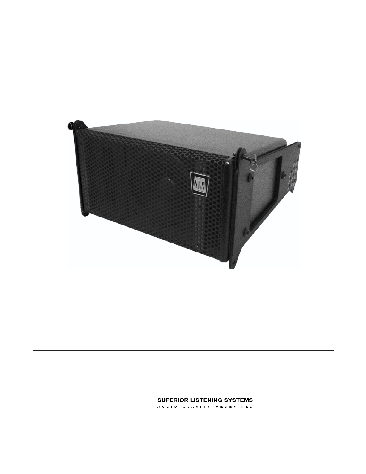
LS6500 Line Array
Assembly Guide
1650 W. Jackson Ozark, MO 65721 (417) 883-4549Rev: 805
Page 2

LS6500 Assembly Guide
Introduction
SLS line array rigging is designed to provide a quick method of flying and shaping line arrays. is Guide
serves as an overview and provides useful hints regarding array construction. Please read in its entirety before
assembling any rigging.
Safety Responsibilities and Liability
All information in this guide is meant only for the purpose of rigging below the SLS supplied Rigging
Frame. All other rigging is considered part of the venue and/or end-user supplied equipment and is not
addressed in this guide. SLS assumes that a working knowledge of accepted rigging practices and safety will
be applied to all rigging materials and practices employed. is guide is not a comprehensive source for
rigging in general. e user must assume all responsibility for the appropriate use of SLS supplied rigging
hardware and follow at a minimum all applicable laws and regulations in force for each venue.
e weakest component determines the safety of the entire rigging assembly. Prior to flying the array, always
inspect all hardware components for wear, deformations, corrosion and missing or damaged parts. Also
inspect the venue attachment points for wear and confirm that the points are suitably load rated for the
suspended array.
No information contained in this guide is intended as a warranty on the part of SLS. Anyone using this
information assumes all liability arising from it’s use. Product abuse, use of the product not in accordance
with SLS instructions or use in an application which the product has not been designed for is not covered
under any SLS warranty nor is SLS liable for any loss or damage.
Users in other countries should not assume that local regulations are based upon North American practices.
Users should consult with local regulatory authorities for specific codes and/or guidelines.
Replacement Parts
All defective components should be replaced with an SLS approved part. Contact the factory directly at
(417) 883-4549 to obtain approved replacement parts. SLS is not responsible for problems caused by using
non SLS supplied parts for the SLS supplied portion of the rigging.
Page 3
LS6500 Assembly Guide (1 of 5)
Note!
LS6500 array components are designed for flown
applications only. For ground-stack applications, use
the LS8695v2-series systems, which share identical
driver components with the LS6500 system.
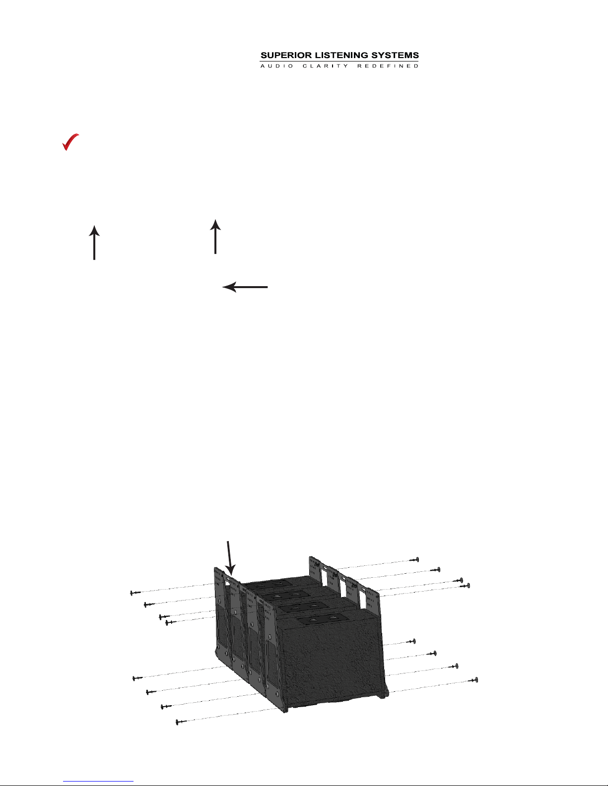
Hardware Billet
Select one LS6500 element to serve as the top element in your
line array design. Remove the pivoting rear billet arms by
removing the cotter assembly. Retain cotter pins and billet
arms as spares.
Assembly:
“O” degree hole
Assemble the LS6500 line array elements in groups of four or
less by laying them face down and pinning the front two points
and the two rear billets at the ‘0’ degree position. Use the
supplied black positive locking pins. Re-position the box
groupings vertically. Make sure the LS6500 with the removed
billets is on top of the grouping.
Page 4
LS6500 Assembly Guide (2 of 5)
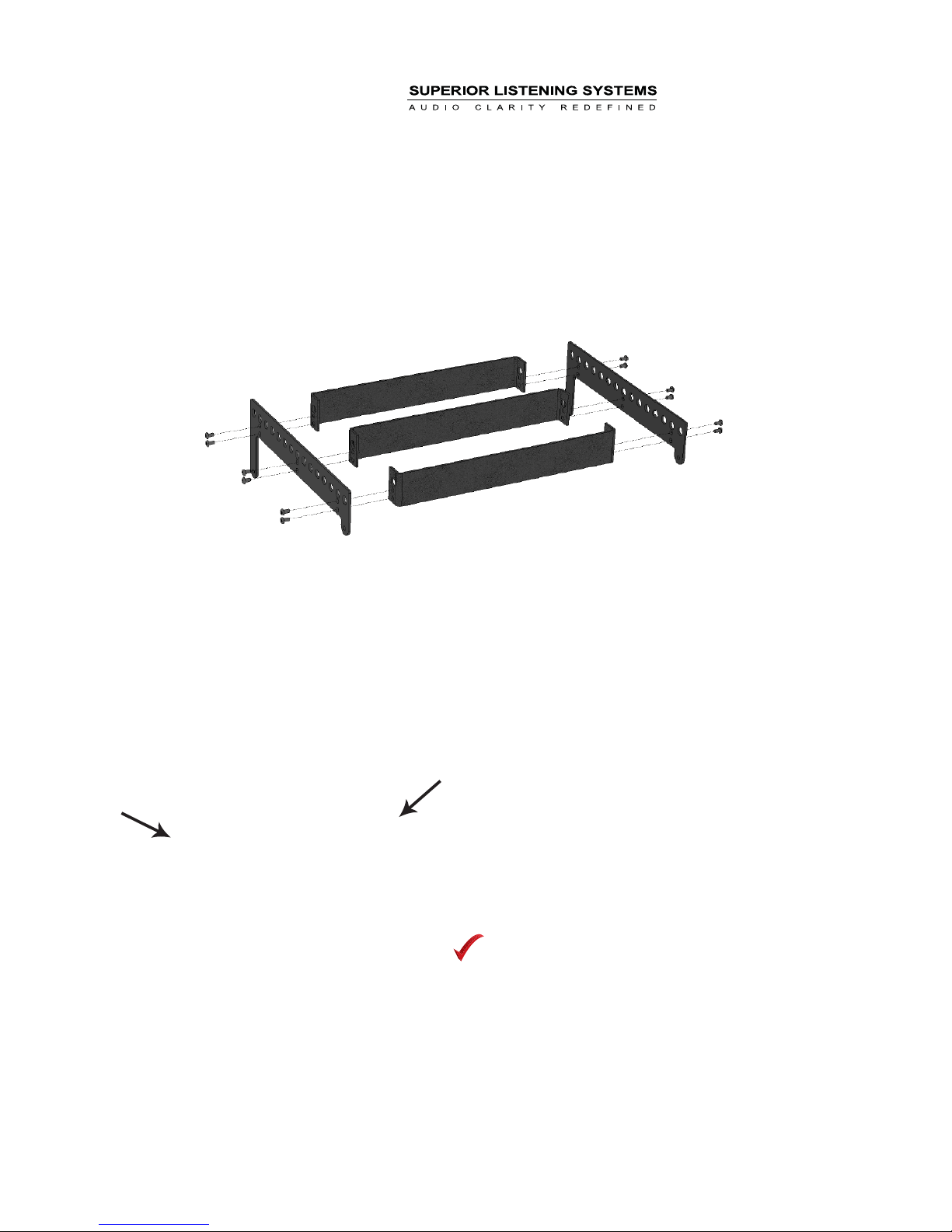
Assemble the RLA/3-BB rigging frame.
Attach the frame to the LS6500 without the rear billets
(previously removed in step 1) using the supplied positive
locking pins (the long extentions of the RLA/3-BB attach to the
rear of the top element in place of the removed rotating billets)
Note!
Use of the optional
SLS road cases store
the LS6500 line
array elements in
this position already.
Page 5
LS6500 Assembly Guide (3 of 5)
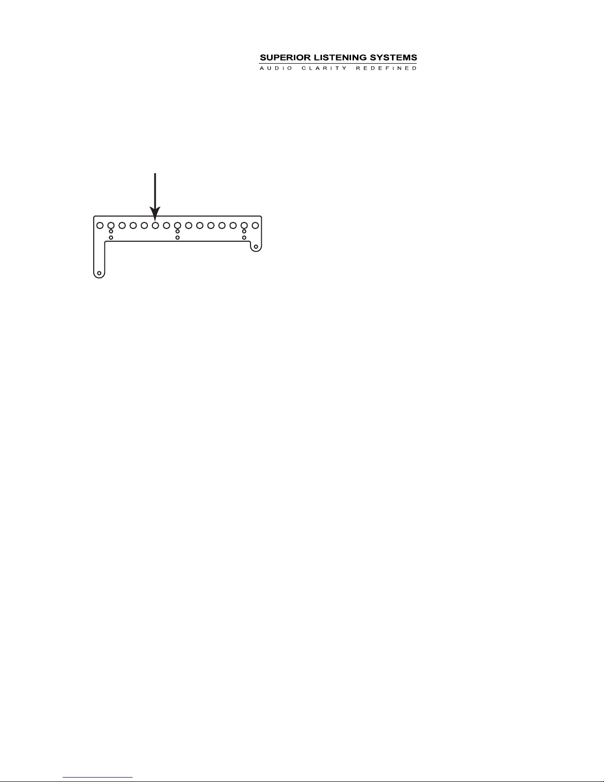
Rigging Points (15 options)
Attach the Rigging Frame to your house rigging on the hole
number calculated by LASS and raise the four LS6500’s to a
comfortable working height. Set the inter-element splay angles
between the array elements, based on the results of your
LASS model. Lift from the bottom to close the articulation
angles as necessary, pinning at the appropriate angle point on
each side (the back pins can be pinned either from the outside
of the rigging plates or from the inside to improve astetics).
Page 6
LS6500 Assembly Guide (4 of 5)
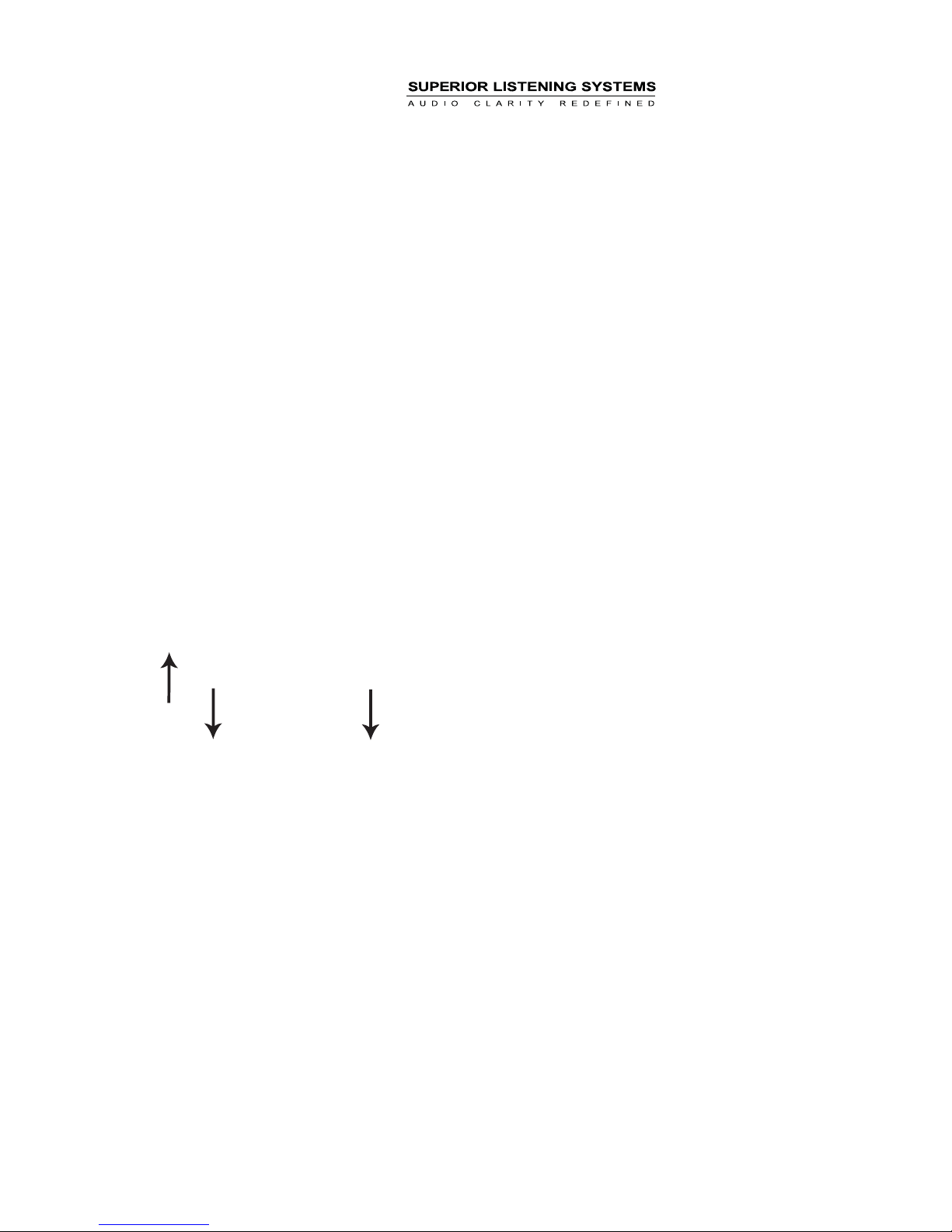
Further raise the array and move the 2nd group of LS6500 line
array elements underneath the flown section. Lower the flown
array and land the elements onto the ground stacked LS6500
group, lining up the front billets. Attach the two front pins
through these front billets, then attach the two rear points
through the splay angle calculated by LASS for that box (you
will most likely have to further lower the flown elements to do
this).
Page 7
LS6500 Assembly Guide (5 of 5)
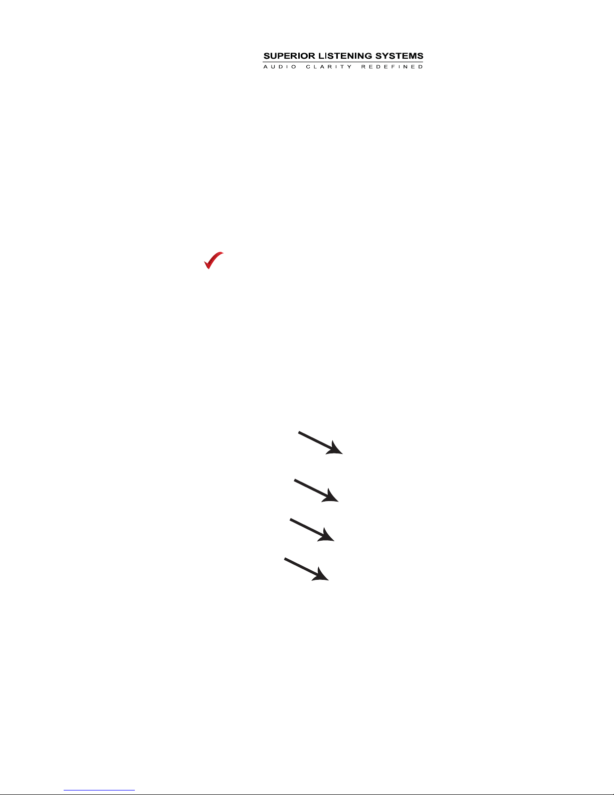
Raise the rigging frame back to a comfortable working height
and adjust the splay angles for all of the second block of
elements. Continue as necessary until the array is complete.
Note!
The Rigging for the
LS6500 system is not
to exceed (24)
LS6500 boxes per
Rigging Frame.
Page 8
LS6500 System Specifcations
Product Specifications
Sensitivity (1W/1M) - Low Freq.
High Freq.
Horizontal Coverage Angle -6dB
Vertical Coverage Angle
Power Handling - Low Freq.
High Freq.
Recommended Amp Power for Max Output
Low Freq.
High Freq.
Max SPL (calculated) 1 Meter - Low Freq.
High Freq.
Nominal Impedance - Low Freq.
High Freq.
Crossover Frequency
Transducers - Low Freq.
High Freq.
Input
Dimensions
Enclosure
Weight
Rigging
Optional Accessories
Finish Options
1
85Hz - 20,000HzOperating Range
2
91dB
101dB
3
110 Degrees
Defined by height and configuration of the
array
4
100W (28 Volts) AES/2
145W (32 Volts) IEC Short Term
46W (18 Volts) IEC Long Term
35W (15.6 Volts) AES/2
200 Watts @ 8 ohms
150 Watts @ 8 ohms
5
111dB Cont. / 117dB Peak
118dB Cont. / 123dB Peak
8 Ohms
7 Ohms
DSP Settings Provided
6.5” Bass/Midrange
PRD500 Ribbon
NL4 x2 (Pair 1 = LF, Pair 2 = HF)
Barrier strip for I version
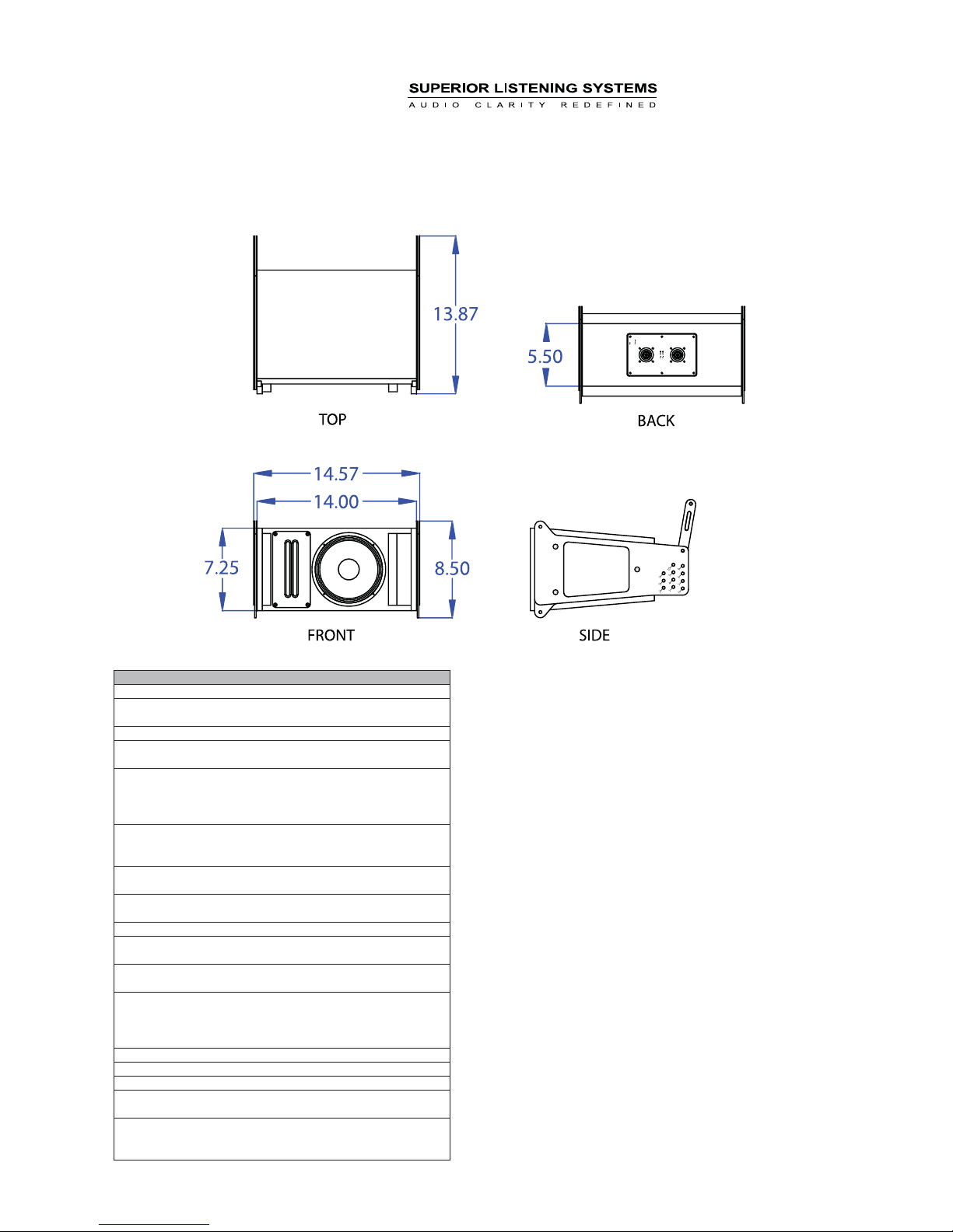
7.25” (18.4cm) H (front side)
5.5” (14cm) H (rear side)
14” (35.6cm) W
10” (25.4cm) D
13ply Baltic Birch
20lbs (9kg) Shipping 26lbs (11.8kg)
All array rigging is included
RLA/3-BB - Rigging Frame
RC-LS6500 Road Case (holds 8 LS6500s)
Black Latex
White Latex (w/ white rigging)
Paintable Natural Finish (w/ black rigging)
1. LF at -10dB, HF -6dB at 40kHz on-axis however response above
20kHz is limited by air absorption and DSP sampling rates in typical PA
applications.
2. Full bandwidth pink noise is applied and amplified to a level and
measured at the loudspeaker terminals - corresponding to 1 Watt as
referenced to the loudspeakers nominal impedance. SPL is measured in
an anechoic environment in the loudspeakers far field. Data is
extrapolated to 1 Meters distance from the loudspeaker.
3. Averaged from 1000Hz to 10kHz
4. AES established with ambient temperature at 22C in accordance with
AES/2-1984 standard. IEC stated in RMS voltage according to IEC 268-5
5. Typical SPL for one box only, for array SPL refer to LASS calculations.
Ribbon SPL calculated from IEC long term and short term
 Loading...