

Page 1

HT805 Series
HT805S - HT805C - HT805T - HT805W
Owner’s Manual
1650 W. Jackson Ozark, MO 65721 (417) 883-4549Rev: 602
Page 2
HT805 Series Owner’s Manual Page 2
Important Safety Instructions
CAUTION
To reduce the risk of electric shock, do not remove the back panel of the HT805W There are no user-serviceable
parts inside. Refer servicing to SLS Loudspeakers or qualified personnel.
General Safety
- Read and follow all warnings, operating and safety instructions in this manual and on the unit.
- Do not use the HT805W near bathtubs, sinks, swimming pools, or other locations where water is present.
- The speakers should be positioned firmly on a level surface. Make sure that the supporting object can
handle the load weight of the speaker.
- The line voltage selection switch must be set for the correct AC voltage present in the region of use
(115VAC or 230VAC). Operating the speaker outside these voltages or opposite of the selector switch
setting may damage the electronics.
- For continued protection against risk of fire, replace only with same type of fuse and rating for operational
voltage selection.
- Do not place the HT805W near heat sources such as stoves, heat registers, radiators, or other appliances
that produce heat.
- Power supply cords should be placed so that they will not be pinched by objects being placed on or
against them.
- During extended periods of non-use, the power cord should be unplugged from the outlet.
- Do not expose the HT805W to rain or moisture. Fire or electrical shock may result.
Compliance
This device complies with part 15 of the FCC Rules. Operation is subject to the following two conditions: (1) This
device may not cause harmful interference, and (2) this device must accept any interference received, including
interference that may cause undesired operation
1650 W. Jackson Ozark, MO 65721 (417) 883-4549Rev: 602
Page 3
HT805 Series Owner’s Manual Page 3
Introduction
Welcome to SLS
Thank you for choosing SLS Loudspeakers! SLS Loudspeakers is a leader in digital amplification and ribbon
technology allowing for a new level of sound reproduction, clarity, and definition. Various technologies and components within the HT805 Series are proprietary to SLS and protected under letters patent. Should you need to
contact SLS you can visit our website at www.slsaudio.com or contact our headquarters:
SLS Loudspeakers
1650 W. Jackson
Ozark, MO 65721
866-395-5345 (Toll Free)
417-883-4549
Unpacking
The HT805 Series loudspeakers are individually shipped in heavy-duty cardboard boxes and are protected inside
by foam packing material.
Step 1: Cut sealing tape on bottom or top end, fold the carton flaps back and invert box and contents.
Step 2: Carefully lift the carton clear of inner contents.
Note: do not cut through carton with sharp objects, as you might damage cabinet finish.
We suggest you retain the packaging for possible future use
CAUTION
The speakers should be positioned firmly on a level surface. Make sure that the supporting object can
handle the load weight of the speaker. If a third party mounting bracket is used, confirm that the bracket is
firmly mounted to the structure. Serious injury can occur from dislodged speakers.
1650 W. Jackson Ozark, MO 65721 (417) 883-4549Rev: 602
Page 4
HT805 Series Owner’s Manual Page 4
General Use and Operation
Loudspeaker Positioning
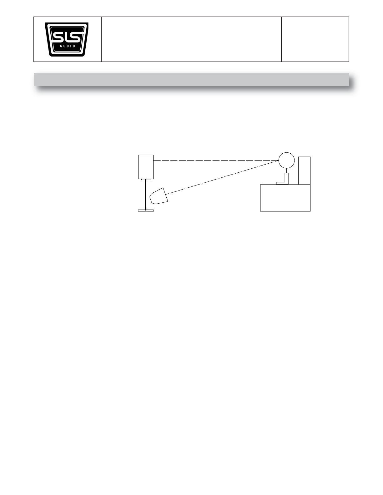
The HT805 Series (except the subwoofer) has a very defined vertical dispersion, which helps prevent interaction
with the floor and ceiling and extends the nearfield listening area. It is important to set the speakers so the ribbon is
approximately at the ear level of the listener(s). The speaker may also be tilted for proper aiming relative to the
height that the speaker is placed.
The HT805S model should be used with a well damped speaker stand or placed on a braced shelf to achieve the
correct height. The best speaker stands are usually hollow steel that are filled with either sand or lead shot. The
TM
cabinet also has a provision for a third party wall mount bracket such as the MultiMount
MM-022 from Allen
Products. The speaker should maintain at least a 6” clearance from the rear wall for proper operation of the bass
port.
The HT805C model comes with a tray for vertical ribbon alignment when it is placed below ear level (such as
underneath a plasma screen). The HT805C can be moved front to back on this tray to adjust the vertical angle of
the cabinet. The cabinet also has a provision for a third party wall mount bracket such as the MultiMount TM
MM-022 from Allen Products. The HT805C may also be used in the upright position with a speaker stand. In this
configuration the ribbon should be rotated 90 degrees.
The HT805T versions are built to the correct height of a typical listening position. They should be placed on the
floor and not be angled vertically. They are provided with adjustable feet for stability and leveling on carpet or hard
surfaces.
The HT805W subwoofer(s) should be placed near or between the front line of speakers. Placing it in a corner will
produce more bass but the sound may loose clarity. We recommend spending some time experimenting with the
best location using the phase and volume level on the subwoofer to determine the best combination for your
particular room and preferences. A shortcut to accomplish this is to temporary place the subwoofer at your primary
listening location. Listen at multiple areas in your room where you could place the subwoofer. Listen to music for
clarity and balance in the bass tones or listen to the noise source in your Home Theater receiver - processor for
smoothness and maximum extension. If you find a spot that you like, move the subwoofer to that spot and the
sound will be matched at your primary listening location. This also can be done when multiple subwoofers are used
in larger rooms. Try to pick spots that are asymmetrical to the room dimensions as it will help overcome some
effects of low frequency room resonances.
1650 W. Jackson Ozark, MO 65721 (417) 883-4549Rev: 602
Page 5
HT805 Series Owner’s Manual Page 5
Loudspeaker Positioning (cont.)
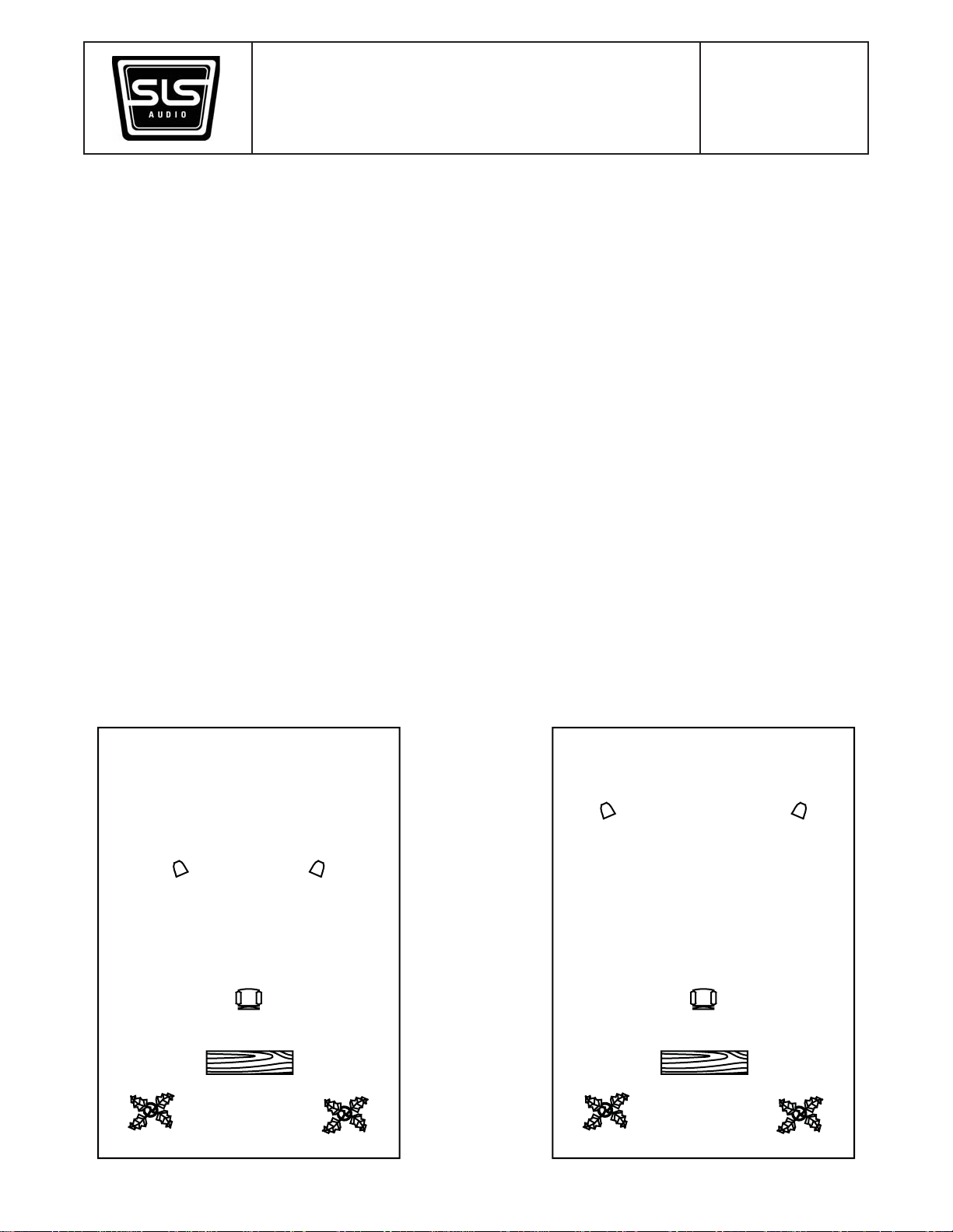
For the best stereo imaging setups, position the speakers and the listening area at approximately the corners of an
equilateral triangle. The larger the triangle, the bigger the soundstage but a less clearly defined center image. The
room will also play an increasing role in the sound. The smaller the triangle, the more immediate the presentation
but with a smaller soundstage. We encourage you to experiment within the following guidelines.
- The speakers should be distanced away from the rear wall at least 6” to allow for proper operation of the
bass port, however for the best presentation in your room the distance between the loudspeaker and the
rd
rear wall should be 1/3
needs to be placed close to the rear wall, it should be treated with a sound absorbing material.
- The listening position should be 2/3
- The speaker position relative to the room’s side walls should not be within 33 percent of the distance to
the back wall in order to smooth room nodes. For an example if the speaker is 4ft from the back wall it
should be no more then 3ft or greater then 5.3ft from the side wall.
the length of the room. If this is not practical try 1/5th the distance. If the speaker
rds
of the way into the room.
- It is also recommended to toe in the left and right speakers so that the ribbon axis is aimed at a point
slightly behind the center of the listening area.
Speakers at 1/3 distance from rear wall
Optimum Setup
Speakers at 1/5 distance from rear wall
2nd Choice Setup
1650 W. Jackson Ozark, MO 65721 (417) 883-4549Rev: 602
Page 6
HT805 Series Owner’s Manual Page 6
Loudspeaker Positioning (cont.)
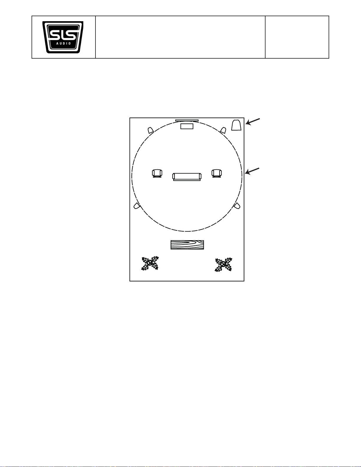
In home theater setups it is best to try and keep all the speakers at an equal distance from the listening position. If
this is not possible, use the level and delay controls on the electronics you are using to level match and time align
the signal from each speaker location. You may use the “Large” speaker setting on all HT805 series models.
HT805W Subwoofer
Virtual Circle where speakers
are placed
Ribbon Rotation
Whatever vertical orientation the speaker ends up in make sure the ribbons rectangular opening is always long
ways up. This provides the best horizontal coverage for the listening area. If the ribbon needs to be rotated,
remove the four screws and gently lift the unit out. Rotate it 90 degrees, place it back in the cabinet and replace the
four screws.
Audio Connection
The HT805 Series (except subwoofer) come standard with dual binding posts that are bi-wire capable. In a normal
setup, attach the positive and negative speaker wire ends to either set of binding posts (red is normally positive,
black negative). The gold plated links that are already attached to the binding posts will route the signal to both the
woofers and the ribbon. If bi-wiring is preferred, remove the links and run 2 pairs of separate cables between the
speaker and amplifier. The ribbon is the top set of binding posts, the woofer(s) the bottom set. Depending on the
cable used, this can sometimes improve resolution of low-level detail. No additional equipment is needed to bi-wire
as removing the links does not bypass the internal crossover network.
1650 W. Jackson Ozark, MO 65721 (417) 883-4549Rev: 602
Page 7
HT805 Series Owner’s Manual Page 7
Audio Connection (cont.)
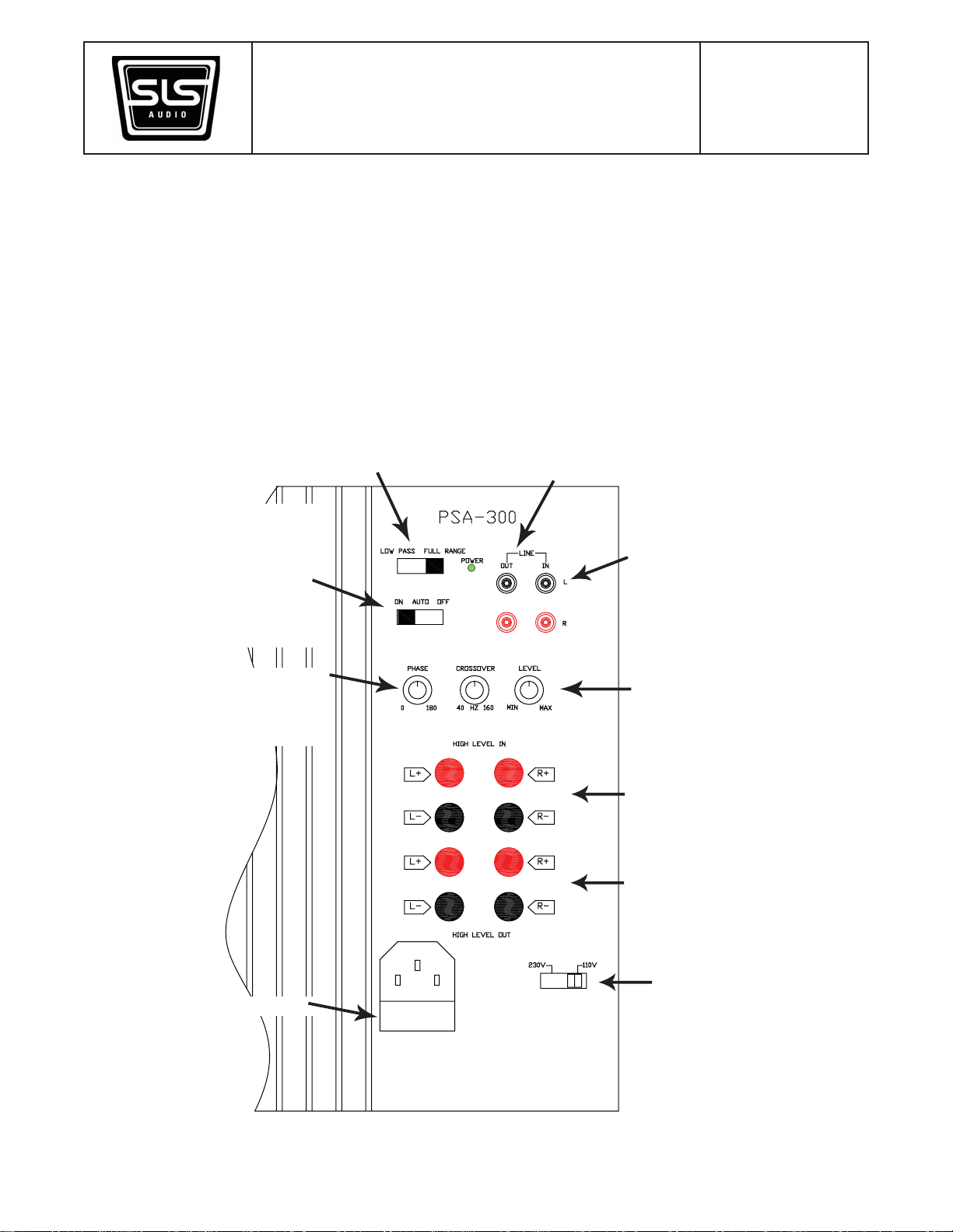
The HT805W subwoofer will accept both line level signals via RCA jacks or speaker level signals from an amplifier
via the binding posts. Do not use a mixture of line level and speaker level connections. Whenever possible, use
the line level connections.
Use of the Full Range setting uses your receiver - processor to control the crossover point between the subwoofer
and satellites. Alternatively, use the Low Pass when
connected to a normal stereo output or when your
receiver - processor settings give unsatifactory results.
Low Pass will engage the crossover knob for high
frequency cut-off adjustment (typically set around 80Hz
when used with the HT Series Satellites)
Power switch for subwoofer
“On” will always apply power, “Auto” will
engage the sense circuit turning off the
subwoofer when no signal is present after a
period of about 5 mins. When signal is
present at the inputs, the subwoofer will
automatically turn on.
Unaltered pass-through output signal (exactly
matches input signal) Used for optional
additional subwoofers or in the case of a line
level stereo output, they would go to the input
of the amplifer for the satellites
Input received from dedicated subwoofer
output on source electronics or a line level
normal stereo output. A dedicated
subwoofer output can use either the left
or right inputs.
Continuously variable phase control.
Adjustments can provide a better blend
between the subwoofer and satellites
when they are remotely located from each
other.
Fuse Holder
Volume adjustment of subwoofer used to
blend in with the satellites
Alternate input (from amplifier powering
stereo pair of speakers)
80Hz high pass filtered output signal
(goes directly to satellite speakers)
Line Voltage Selector Switch
1650 W. Jackson Ozark, MO 65721 (417) 883-4549Rev: 602
Page 8
HT805 Series Owner’s Manual Page 8
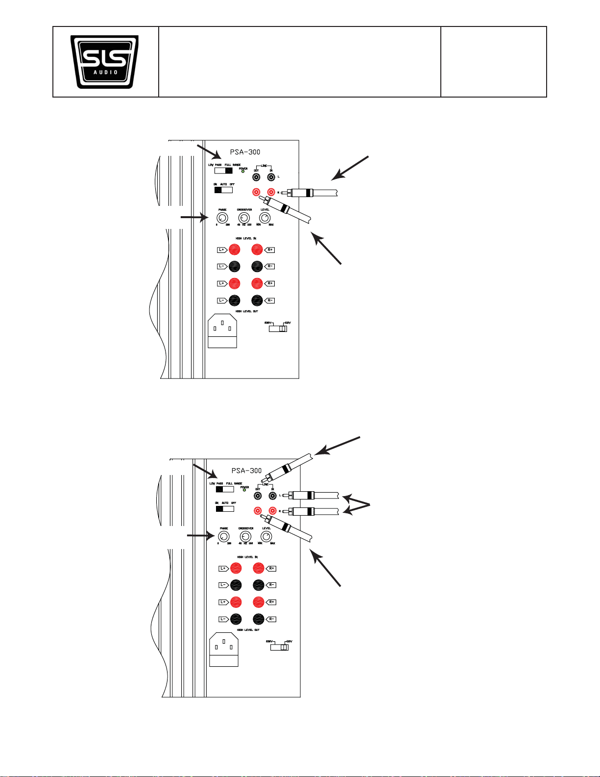
Connection Diagram using a dedicated subwoofer output
Switch set to FULL RANGE
Adjust level and phase
(crossover disabled)
Input signal from dedicated subwoofer
output on receiver - processor
Output signal to optional 2nd subwoofer
Connection Diagram using a line level stereo output
Output signal to amplifier powering the
satellites
Switch set to LOW PASS
Adjust crossover, level and
phase
Stereo line level signal from preamplifier
(preferabley a 2
from preamplifiers that have two outputs,
the 1st output would go directly to the
amplifier powering the satellites. A “Y”
cable at the preamplifer for each channel
can also be used to accomplish the same
purpose)
Output signal to amplifier powering the
satellites
1650 W. Jackson Ozark, MO 65721 (417) 883-4549Rev: 602
nd
independent signal
Page 9
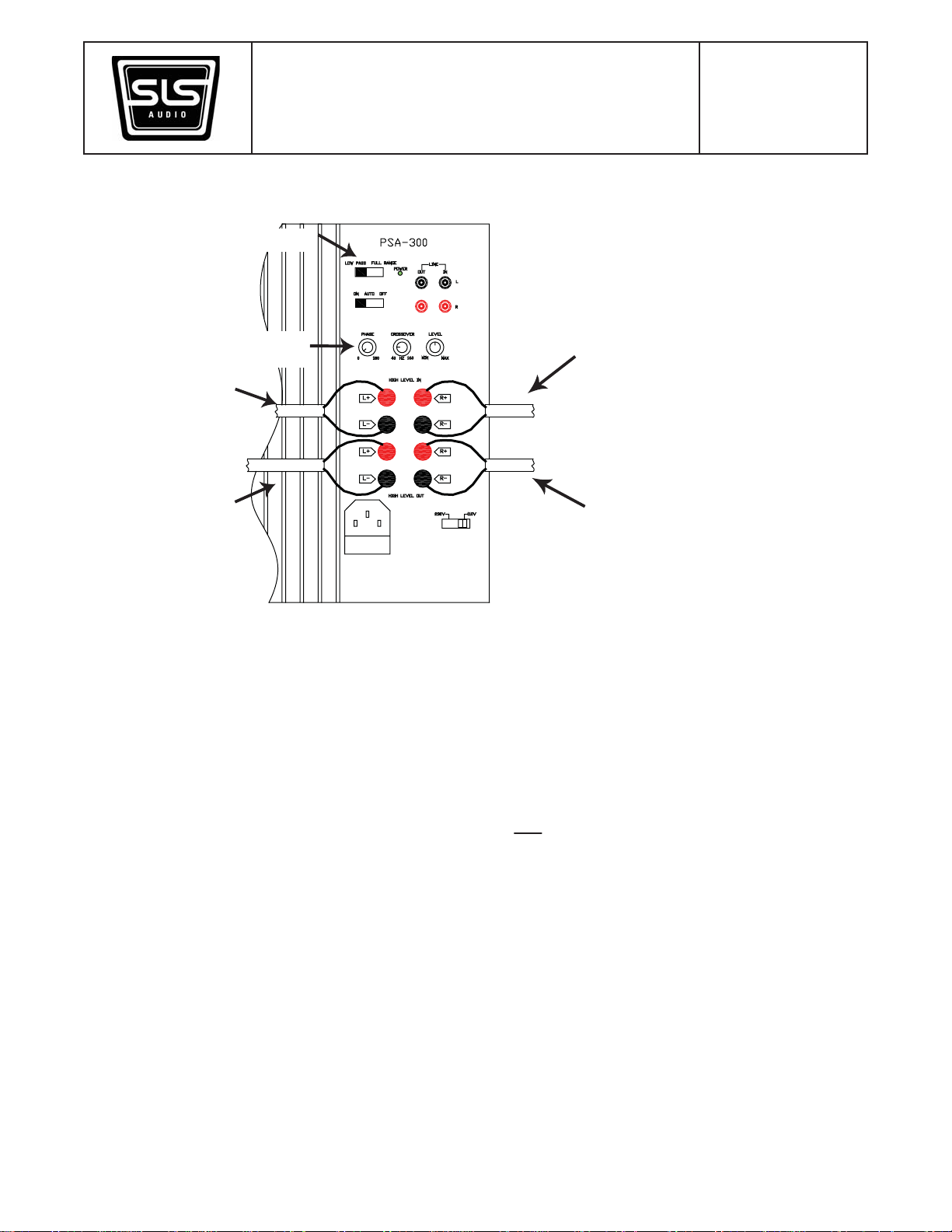
Connection Diagram using a speaker level stereo output
Switch set to LOW PASS
HT805 Series Owner’s Manual Page 9
Adjust crossover, level and
phase
Input signal from speaker
output of receiver or
power amplifier
80Hz High Pass Output
signal directly to satellites
Input signal from speaker output of
receiver or power amplifier
80Hz High Pass Output signal
directly to satellites
Stray Magnetic Fields
The ribbon used in the HT805 series does not produce any stray magnetic fields however the high performance
woofers used in the designs do create a small field. We recommend that all susceptible display devices maintain at
least 12” clearance from the speaker enclosures. These would not
include Plasma, projection or LCD televisions.
Those technologies are immune to magnetic interference.
Finish Care
All cabinets in the HT805 series feature high quality finishes. Care for them as you would any piece of fine furniture.
Break In
The HT805 series benefits from a 24 hour break-in period at reasonable sound level before reaching optimum
sound quality.
1650 W. Jackson Ozark, MO 65721 (417) 883-4549Rev: 602
Page 10
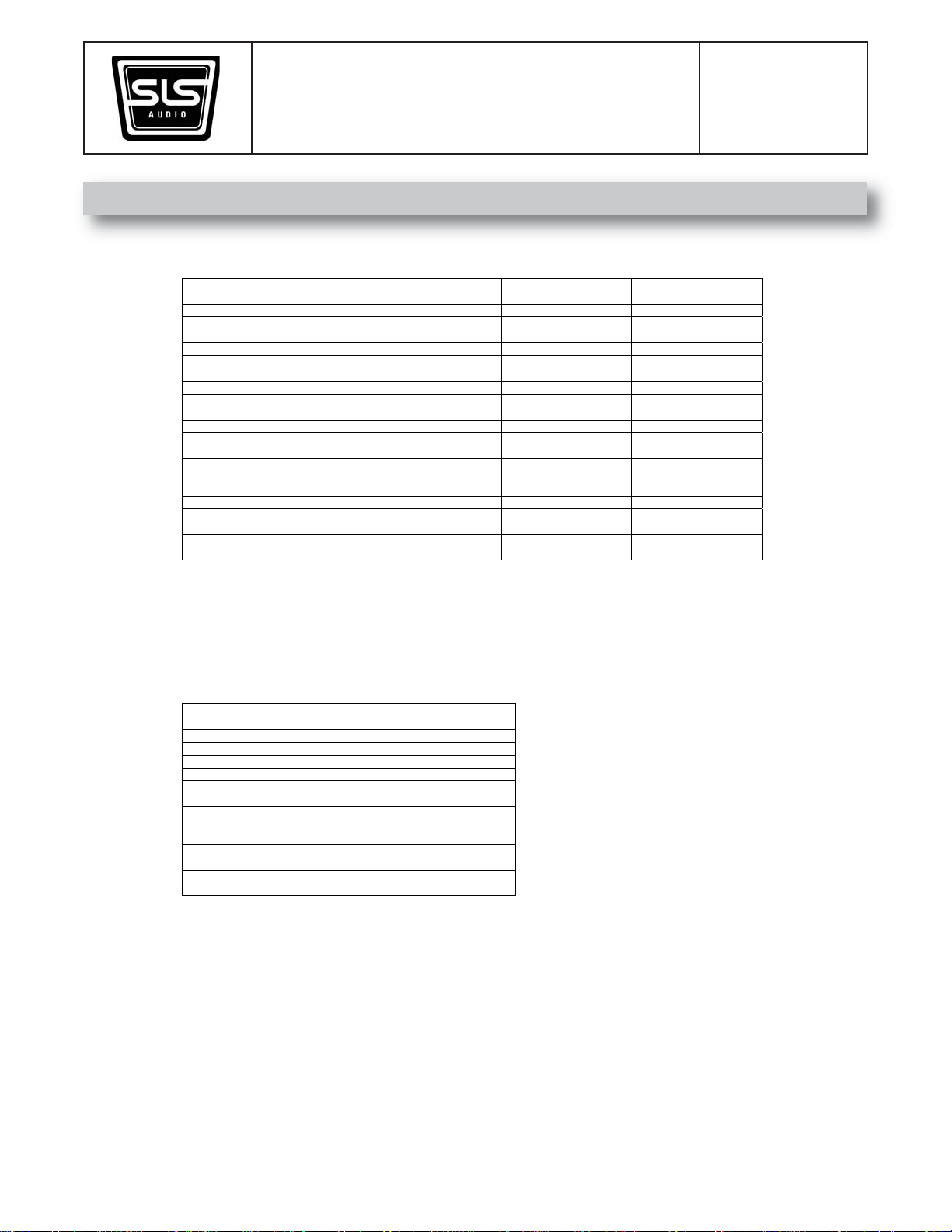
4. Specifications
Horizontal Coverage Angle -6dB 120 Degrees 120 Degrees 120 Degrees
Vertical Coverage Angle -6dB 30 Degrees 30 Degrees 30 Degrees
Max SPL(calculated) @ 1 Meter 111dB Cont. / 117dB Peak 117dB Cont. / 123dB Peak 117dB Cont. / 123dB Peak
Recommended Amp Power for Max Output 250 Watts 500 Watts 500 Watts
HT805 Series Owner’s Manual Page 10
Model HT805S HT805C HT805T
Operating Range 44 – 40,000Hz 52 – 40,000Hz 30 – 40,000Hz
Sensitivity (1W/1m) 90dB 93dB 93dB
Power Handling 125 Watts RMS 250 Watts RMS 250 Watts RMS
Nominal Impedance 8 Ohms 4 Ohms 4 Ohms
Crossover Frequency 1500Hz Passive 1500Hz Passive 1500Hz Passive
Transducers – High Freq. PRD500 Ribbon PRD500 Ribbon PRD500 Ribbon
Low Freq. 8” Woofer 8” Woofer x2 8” Woofer x2
Dimensions
Mounting
Finish Options
Dual Binding Posts in Bi-
Input
Wire Configuration
19” (48.3cm)H
10.5” (26.7cm)W
11.25” (28.6cm)D
Weight 25lbs (11.3kg) 40lbs (18kg) 66lbs (30kg)
Attachment Point for 3
Party Hardware
Rosenut, Cherry and
High Gloss Black
Dual Binding Posts in BiWire Configuration
10.5” (26.7cm)H
27” (68.5cm)W
11.25” (28.6cm)D
rd
Attachment Point for 3rd
Party Hardware
Rosenut, Cherry and
High Gloss Black
Dual Binding Posts in BiWire Configuration
45” (114.3cm)H
10.5” (26.7cm)W
12.5” (31.8cm)D
Floor Standing Only
Rosenut, Cherry and
High Gloss Black
Model HT805W
Max SPL(calculated) @ 1 Meter 115dB Cont. / 121dB Peak
Operating Ran ge 28 – 160 Hz
Amp Power 300 Watts
Crossover Frequency 50Hz – 160Hz Variable
Transducer 12” High Excursion Poly-cone
Input/Output Connections
Dimensions
Mounting Floor Standing Only
Finish Options
Low Level RCA L/R
Speaker Level Binding Post L/R
18” (45.7cm)H
15.25” (38.7cm)W
18.5” (47cm)D
Weight 60lbs (27kg)
Rosenut, Cherry and
High Gloss Black
1650 W. Jackson Ozark, MO 65721 (417) 883-4549Rev: 602
 Loading...