

Page 1
Attention, Consult
Accompanying Documents
Alternating Current
Attention, Dangerous Voltages
Earth (Ground)
EXPLANATION OF SYMBOLS
Direct Current
CONDOR DC POWER SUPPLIES INC.
2311 STATHAM PKWY
OXNARD, CA 93033 + 805-486-4565
Internet: www.condorpower.com
MODEL NUMBERS: GPC40A, GPC40B, GPC40D, and GPC40-X, where X represents the output voltage, which may be
any number from 3.3 through 28. Models may or may not be followed by suffix –XXX and/or G, where XXX may be any
number from 001 thru 999. The –XXX suffix are used for value added configurations that have no impact on safety and
suffix G indicates compliance to RoHS.
RATINGS:
Input: 100-240 V ac, 1.3 A, 50/60 Hz
Outputs: 40 W max or see table for standard output voltage models.
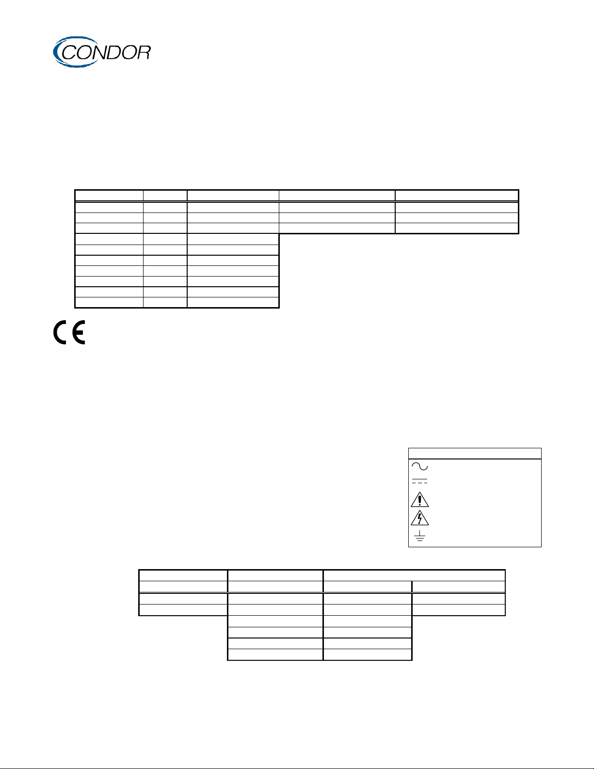
Model Watts1 Output #1 Output #2 Output #3
GPC40A 40 +5.1 V dc 4 A +12 V dc 2 A -12 V dc 0.4 A
GPC40B 40 +5.1 V dc 4 A +15 V dc 2 A -15 V dc 0.4 A
GPC40D 40 +5.1 V dc 4 A +24 V dc 1 A -12 V dc 0.4 A
GPC40-3.3 26.4 3.3 V dc 8 A
Notes:
GPC40-5 40 5.0 V dc 8 A
1. Maximum continuous output power at 50 °C - Total
GPC40-9 40 9.0 V dc 4.4 A
of all Outputs.
GPC40-12 40 12.0 V dc 3.4 A
2. Maximum Relative Humidity 96 %, no condensation.
GPC40-15 40 15.0 V dc 2.7 A
3. Storage: -40 to +85 °C. Units should be allowed to warm-up
GPC40-24 40 24.0 V dc 1.7 A
under non-condensing conditions before application of power.
GPC40-28 40 28.0 V dc 1.5 A
SAFETY DECLARATION: Condor DC Power Supplies, Inc. declares under our sole responsibility that all
models listed above are in conformity with the applicable requirements of EN 60950-1 following the provisions of
the Low Voltage Directive 73/23/EEC. All models are Certified to be in compliance with the applicable
requirements of UL 60950-1, CSA 22.2 No. 60950-1-03 (L3M1), and EN 60950-1 for Pollution Degree 2 environment and
Class I TN-S power systems. The output(s) of these supplies meet the requirements for SELV and are not an energy hazard.
GROUNDING: The Earth (Ground) terminal must be bonded to Protective Earth in the end application. Using this terminal
for the end product protective earthing terminal is not recommended. A separate dedicated protective earthing point should
be used.
SPACINGS: Creepage and clearance distances from primary circuits to ground and secondary circuits, as defined in the
applicable safety standards, must be maintained after installation to preserve the intended safety.
TEMPERATURES: The maximum operating temperatures of certain safety
components, as defined in the applicable safety standards, must not be exceeded after
installation to preserve the intended safety. The output power, ambient air temperature
and the availability, amount, direction and/or restriction of airflow influence the
temperatures of these components.
WARNING! RISK OF FIRE! A blown fuse is an indication of catastrophic failure of
circuit component(s). Repair must be performed by Condor authorized personnel. Fuse
F1 must be replaced with F 2 A 250 V (fast blow), UL Listed and CSA Certified type.
WARNING! SHOCK HAZARD! Dangerous voltages are present on some
components and printed wiring traces.
C O N N E C T I O N S
Multi-Output Models Single Output Models
J1 AC Input J2 DC Outputs J2 DC Output J3
1) Line 1) Output 2 (+) 1) Output 1 (+) 1) + Sense
3) Neutral 2) Output 1 (+) 2) Output 1 (+) 2) Com Sense
CAUTION:
3) Output 1 (+) 3) Output 1 (+)
Do not exceed 5 A per contact on J2. 4) Common 4) Common
5) Common 5) Common
6) Output 3 (-) 6) Common
Mating Connectors: Amp P/N 640250-3 Amp P/N 640250-6 Amp P/N 640250-6 Amp MTA100 Series
Contacts: Amp P/N 770476-1 Amp P/N 770476-1 Amp P/N 770476-1
Condor DC Power Supplies Inc. wil l not be liable for the safety, reliability or performance of these power supplies i f a) any changes, modifications or repairs are carried out by other than
authorized agents of Condor DC Power Suppli es Inc., or b) the i nstallation of the supply is not in accordance with these installation instructions and the applicable UL, CSA, EN/IEC safety
standards.
41-32579-0001 Rev. G 11/03/05
GPC40 SERIES
INSTALLATION INSTRUCTIONS
 Loading...