

Page 1
SL Power Electronics, Corp..
6050 King Dr. Bldg. A
VENTURA, CA 93003 + 805-486-4565
INSTALLATION INSTRUCTIONS
GLM50 SINGLE OUTPUT SERIES
MODEL NUMBERS: GLC50-X-YYYG, where X represents the output voltage which may be any number from 3.3 thru
48, -YYY represents Value Added Options not related to Safety and G represents compliance to RoHS. Model may be
followed by suffix –C for chassis & cover option.
R A T I N G S
Input: 100-240 VAC, 1.4 A, 50/60 Hz
Output:
Model Watts1 Output Model Watts1 Output
GLM50-3.3 26.4 +3.3VDC 8A GLM50-15 50 +15VDC 3.3A
GLM50-5 40 +5.1VDC 8A GLM50-24 50 +24VDC 2.1A
GLM50-12 50 +12VDC 4.2A GLM50-28 50 +28VDC 1.8A
Notes:
1. -C option requires 24 cfm minimum airflow for full rated output power.
2. Maximum operating ambient is 50°C.
3. Maximum Relative Humidity 96%, no condensation.
CERTIFICATION: All models are Certified to be in compliance with the applicable requirements of
UL/CSA/EN/IEC 60601-1.
CLASSIFICATION:
(In accordance with sub-
clause 5 of IEC 601-1)
(5.1) Protection against electric shock = Class I
(5.2) Degree of protection against electric shock = Signal output or intermediate
(5.3) Protection against harmful ingress of water = Ordinary (no protection)
(5.5) Have not been evaluated for use in the presence of a flammable anaesthetic
mixture with air, oxygen, or nitrous oxide. This evaluation is to be made
on the end equipment by the OEM.
(5.6) Mode of operation = Continuous
SAFETY DECLARATION:
that all models listed above are in conformity with the applicable requirements of EN60950 following the
provisions of the Low Voltage Directive 2006/95/EC.
SL Power Electronics Corp (SLPE). declares under our sole responsibility
GROUNDING: The Protective Earth (ground) terminal must be bonded to Protective Earth
in the host equipment. Using the Protective Earth terminal on the supply for grounding the host
equipment is not recommended. A separate dedicated grounding point should be used.
OUTPUTS: Output common should be connected to Protective Earth in the end application. The
output is intended for Protectively Earthed Signal Output and Intermediate Circuits only. The output is
not acceptable for patient connection without additional isolation. The DC output is SELV under normal
and single fault conditions.
OVERVOLTAGE PROTECTION: The output is monitored for an overvoltage condition. In some
applications where an overvoltage condition could result in a hazard as defined in applicable safety
standards, redundant or additional overvoltage protection may be required. Consult factory for details.
CAUTION: When performing Dielectric Strength Tests, catastrophic failure of the unit may result if a
Dielectric Strength test voltage greater than 1800 V ac is applied between primary and secondary
circuits. The components providing isolation from primary to secondary cannot be tested while installed
in the power supply without overstressing basic (primary to ground) insulation. All isolating
components are individually 100 % tested at 4800 V ac prior to installation.
41-34648-0001 Rev. E 3/28/08
Page 1 of 2
Page 2
ISOLATION: The creepage distance between primary and ground is 4 mm minimum; between primary
and secondary circuits is 8 mm minimum. Secondary to ground creepage is not defined or controlled.
The output common is bypassed to ground using a 2200 pF 1 kV capacitor. The required creepage and
clearance distances from primary circuits to ground and secondary circuits must be maintained after
installation to preserve the intended safety.
TEMPERATURES: The maximum operating temperatures of certain safety components, as defined in
the applicable safety standards, must not be exceeded after installation to preserve the intended safety.
The output power, ambient air temperature and the availability, amount, direction and/or restriction of
airflow influence the temperatures of these components.
OVERCURRENT PROTECTION: The internal fuse is located in the phase lead only. EN 60601-1
requires that both supply leads (phase and neutral) be protected against overcurrent. Complete
overcurrent protection must be provided in the host equipment. Fuse ratings must not exceed that
specified for the internal fuse, must meet the requirements of EN 60601-1, and be acceptable for the
country in which the host equipment is to be installed.
WARNING! RISK OF FIRE! A blown internal fuse is an indication of catastrophic failure of circuit
component(s). Refer to fuse marking on the supply for rating. Repair must be performed by SLPE
authorized personnel.
WARNING! SHOCK HAZARD! Dangerous voltages are present on some components, printed wiring
traces and heatsinks.
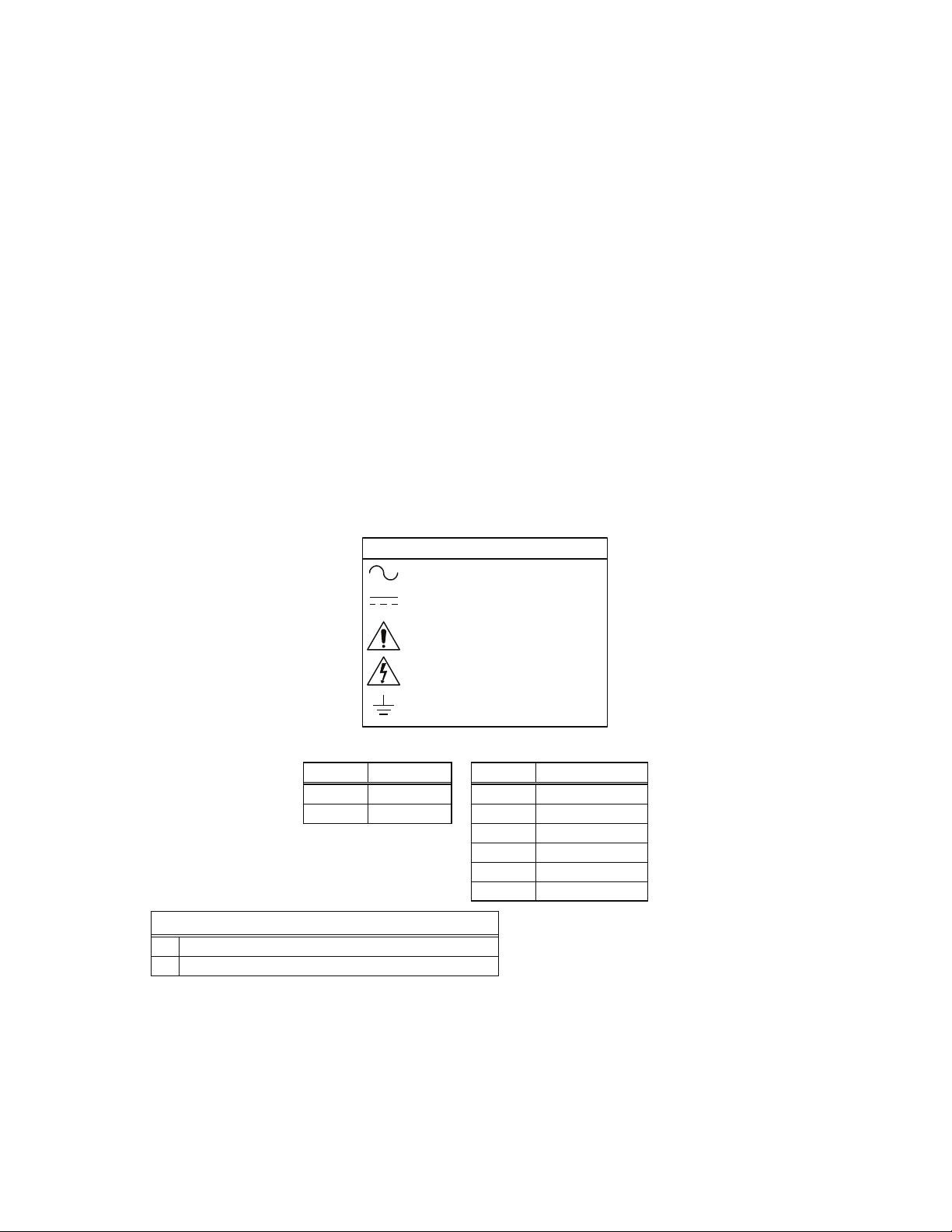
EXPLANATION OF SYMBOLS
Alternating Current
Direct Current
Attention, Consult
Accompanying Documents
Attention, Dangerous Voltages
Earth (Ground)
C O N N E C T I O N S
J1 Pin AC Input
1 Line 1 Output #1 (+)
3 Neutral 2 Output #1 (+)
3 Output #1 (+)
4 Return
5 Return
RECOMMENDED MATING CONNECTORS
J1 Amp Housing 640250-3 Contact 770522
J2 Amp Housing 640250-6 Contact 770522
SLPE. will not be liable for the safety, reliability or performance of these power supplies if a) any changes, modifications or repairs are carried out by other than authorized agents of
SLPE., or b) the installation of the supply is not in accordance with these installation instructions and the applicable UL, CSA, and EN/IEC safety standards.
41-34648-0001 Rev. E 3/28/08
6 Return
J2 Pin DC Output
Do not exceed 5 Amps per contact.
CAUTION
Page 2 of 2
 Loading...