

Page 1
Code No. 0816555
INSTALLATION INSTRUCTIONS FOR DUAL-FLUSH FLUSHOMETERS
Rev. 2 (08/12)
WES-111
Exposed Closet
Flushometer
for 1-1/2 Top Spud
EXPOSED TOP SPUD
1½” WATER CLOSET
• MODEL 111
• MODEL 113
• MODEL 115
• MODEL 116
EXPOSED REAR SPUD
1½” WATER CLOSET
• MODEL 120
Unless otherwise noted, Sloan Valve Company warrants this product, manufactured and sold
for commercial or industrial uses, to be free from defects in material and workmanship for
a period of three (3) years (one (1) year for special finishes, SF faucets, PWT electronics
and 30 days for PWT software) from date of first purchase. During this period, Sloan Valve
Company will, at its option, repair, replace, or refund the purchase price of any product which
fails to conform with this warranty under normal use and service. This shall be the sole and
exclusive remedy under this warranty. Products must be returned to Sloan Valve Company,
at customer’s cost. No claims will be allowed for labor, transportation or other costs. This
warranty extends only to persons or organizations who purchase Sloan Valve Company’s
products directly from Sloan Valve Company for purpose of resale. This warranty does not
cover the life of the batteries.
THERE ARE NO WARRANTIES WHICH EXTEND BEYOND THE DESCRIPTION ON
THE FACE HEREOF. IN NO EVENT IS SLOAN VALVE COMPANY RESPONSIBLE
FOR ANY CONSEQUENTIAL DAMAGES OF ANY MEASURE WHATSOEVER.
PRIOR TO INSTALLATION
Before you install the flushometer, be sure the items listed below are installed.
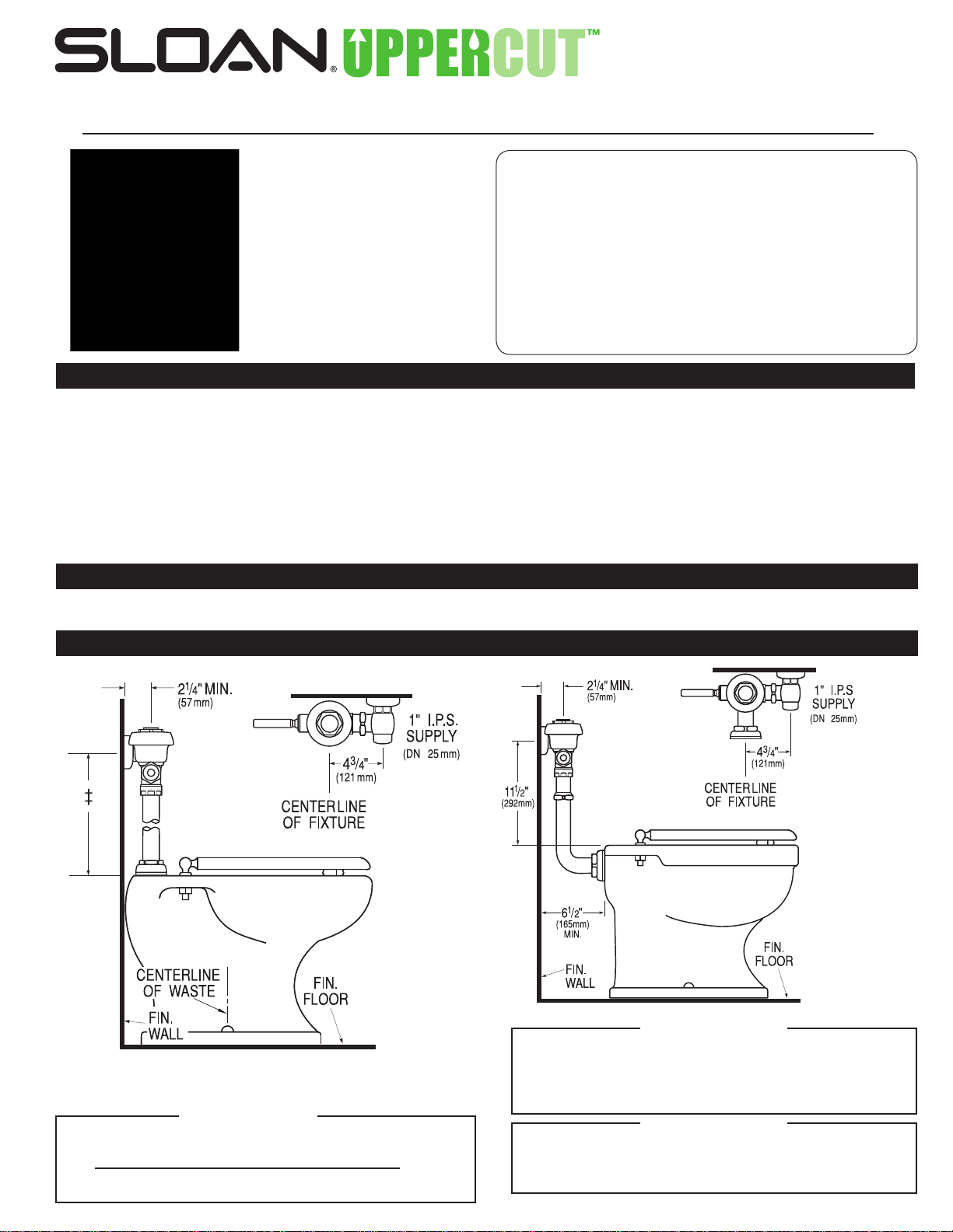
Also, refer to the rough-in diagram below.
• Closet fixture
• Drain line
• Water supply line
IMPORTANT:
• ALLPLUMBINGSHOULDBEINSTALLEDINACCORDANCE
WITH APPLICABLE CODES AND REGULATIONS.
• WATERSUPPLYLINESMUSTBESIZEDTOPROVIDEAN
ADEQUATE VOLUME OF WATER FOR EACH FIXTURE.
• FLUSHALLWATERLINESPRIORTOMAKING
CONNECTIONS.
Sloan’s flushometers are designed to operate with 10 to 100 psi (69 to 689
kPa) of water pressure.
TO THE VALVE IS DETERMINED BY THE TYPE OF FIXTURE
SELECTED.
requirements. Most Low Consumption water closets (1.6 gpf/6.0 Lpf) require a
minimum flowing pressure of 25 psi (172 kPa).
TOOLS REQUIRED FOR INSTALLATION
• Straight blade screwdriver
• Sloan A-50 Super-Wrench™, Sloan A-109 Plier Wrench or smooth jawed spud wrench
ROUGH-IN
MODEL 120MODELS 111, 113, 114, 115, 116
LIMITED WARRANTY
THE MINIMUM PRESSURE REQUIRED
Consult fixture manufacturer for minimum pressure
‡ Model 111 – 11½” (292 mm)
Model 113 – 16” (406 mm)
Model 114 – 34⅜” (873 mm)
Model 115 – 24” (610 mm)
Model 116 – 27” (686 mm)
!!! IMPORTANT !!!
When mounted on an ADA accessible bowl, the rough-in to the supply
inlet should be no higher than 37½” or the handle will exceed maximum
New ADAAG Guidelines allow for Split or Offset Grab Bars, check with
height allowances under ADA guidelines.
local authorities or reference section 604.5.2 of ADAAG.
!!! IMPORTANT !!!
Protect the chrome or special finish of Sloan Flushometers — DO
NOT USE toothed tools to install or service these valves. Use a
Sloan A-50 Super-Wrench™, Sloan A-109 Plier Wrench or smooth
jawed spud wrench to secure all couplings. Also see “Care and
Cleaning” section of this manual.
!!! IMPORTANT !!!
This product contains mechanical and/or electrical components
that are subject to normal wear. These components should be
checked on a regular basis and replaced as needed to maintain
the valve’s performance.
Page 2
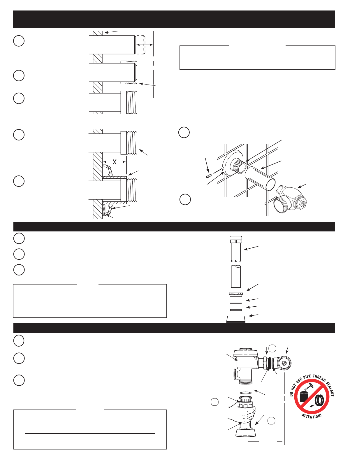
1 - INSTALL OPTIONAL SWEAT SOLDER ADAPTER (ONLY IF YOUR SUPPLY PIPE DOES NOT
HAVE MALE THREAD)
FINISHED WALL
Measure from finished wall to
A
C/L of fixture spud. Cut pipe
1⁄” (32 mm) shorter than this
measurement. Chamfer O.D.
and I.D. of water supply pipe.
Slide threaded adapter fully
B
onto pipe.
Sweat solder the adapter to pipe.
C
Measure from finished wall
A
to first thread of adapter
or threaded supply pipe
(dimension “X”). Cut cover
tube to this length.
Slide cover tube over pipe.
B
Slide wall flange over cover
tube until against wall.
WATER SUPPLY PIPE
WATER
SUPPLY PIPE
SWEAT
SOLDER ADAPTER
COVER TUBE
WALL
FLANGE
SET SCREW
1-1/4”
(32 mm)
SWEAT
SOLDER
ADAPTER
C/L OF
FIXTURE
SPUD
!!! IMPORTANT !!!
WITH THE EXCEPTION OF THE CONTROL STOP INLET, DO
NOT USE PIPE SEALANT OR PLUMBING GREASE ON ANY
Thread Control Stop onto pipe. Tighten
C
with a wrench.
SET SCREW
SUPPLY
FLANGE
Tighten Set Screw with a 1/16”
D
VALVE COMPONENT OR COUPLING!
IRON PIPE NIPPLE OR
COPPER PIPE WITH SWEAT
SOLDER ADAPTER
COVER TUBE
BAK-CHEK
CONTROL STOP
hex wrench. DO NOT install Vandal
Resistant Stop Cap at this time.
3-INSTALLVACUUMBREAKERCONNECTION
®
Slide spud coupling, nylon slip gasket, rubber gasket and spud flange
A
over vacuum breaker tube.
Insert tube into fixture spud.
B
Hand tighten spud coupling onto fixture spud.
C
NOTE
Follow instructions on bag of high back pressure vacuum
breaker kit included with flushometer: insert baffle into
groove of vacuum breaker sack; insert sack in vacuum
breaker tube; and place friction ring on top of sack.
4 - INSTALL FLUSHOMETER
Lubricate tailpiece o-ring with water. Insert adjustable tailpiece into
A
control stop. Tighten tailpiece coupling by hand.
Align flushometer directly above the vacuum breaker flush connection
B
by sliding the flushometer body IN or OUT as needed. Tighten vacuum
breaker coupling by hand.
Align flushometer body and securely tighten first the tailpiece coupling
C
(1), then the vacuum breaker coupling (2), and finally the spud
coupling
shown.
MAXIMUM adjustment of Sloan adjustable tailpiece is
½” (13 mm) IN or OUT from the standard 4¾” (121 mm)
(centerline of flushometer to centerline of control stop).
If roughing-in measurement exceeds 5¼” (133 mm), a
(3). Use a wrench to tighten these couplings in the order
NOTE
longer tail may be supplied.
FLUSHOMETER
BODY
VACUUM
BREAKER
COUPLING
2
VACUUM
BREAKER
FLUSH
CONNECTION
VACUUM
BREAKER TUBE
SPUD
COUPLING
NYLON SLIP
GASKET
RUBBER GASKET
SPUD FLANGE
TAILPIECE
COUPLING
1
O-RING
ADJUSTABLE TAILPIECE
C/L
FIXTURE
G-44
FRICTION
RING
SPUD
COUPLING
3
4-3/4”
(121 mm)
±1/2”
(13 mm)
CONTROL
STOP
C/L
SUPPLY
Page 3

5-INSTALLDUAL-FLUSHHANDLEASSEMBLYANDGASKET(IFNOTALREADYINSTALLED)
Install Handle
A
with “line”
indicator on
Label facing
“UP.”
HANDLE ASSEMBLY
HANDLE
COUPLING
A-31
GASKET
6 - FLUSH OUT SUPPLY LINE
Make sure control stop is
A
CLOSED and remove flushometer
outer cover.
Remove inside cover and lift out Inside
B
parts assembly.
Tighten Handle Coupling securely.
B
Reinstall outside and inside cover wrench
C
tight. Open control stop to flush supply
line. Close control stop and remove
outside and inside cover.
D
Reinstall inside parts assembly, inside
cover and outside cover wrench tight.
7 - ADJUST CONTROL STOP AND INSTALL VANDAL RESISTANT STOP CAP
Open control stop
A
COUNTERCLOCKWISE
one FULL turn from
closed position.
Activate flushometer.
B
Adjust control stop after each flush until the rate of flow delivered
C
properly cleanses the fixture.
TURN COUNTER-
CLOCKWISE TO OPEN
TURN CLOCKWISE
TO CLOSE
SLOAN’S FLUSHOMETERS ARE ENGINEERED FOR QUIET
OPERATION. EXCESSIVE WATER FLOW CREATES NOISE,
WHILE TOO LITTLE WATER FLOW MAY NOT SATISFY THE
NEEDS OF THE FIXTURE. PROPER ADJUSTMENT IS MADE
WHEN PLUMBING FIXTURE IS CLEANSED AFTER EACH
FLUSH WITHOUT SPLASHING WATER OUT FROM THE LIP
AND A QUIET FLUSHING CYCLE IS ACHIEVED.
Thread plastic sleeve onto stop
D
bonnet until snug (hand tighten only;
do not use pliers or a wrench).
E
Place metal stop cap over plastic
sleeve. Use palm of hand to push or
“pop” Stop cap over fingers of plastic
sleeve. Stop cap should spin freely.
!!!IMPORTANT!!!
H-700-A BAK CHEK
CONTROL
STOP BONNET
CONTROL STOP CAP
®
CONTROL STOP
PLASTIC SLEEVE
8 - INSTALL DUAL-FLUSH INSTRUCTION PLATES (RECOMMENDED PLATE LOCATIONS)
Install Plate
B
Install Plate centered
A
over flush valve.
on stall door.
Page 4

VANDAL RESISTANT CONTROL STOP CAP
REMOVAL
Use a large flat screwdriver as a lever to remove the cap from the
control stop. Insert the screwdriver blade between the bottom
edge of the cap and the flat surface of the control stop body
as shown. Push the screwdriver handle straight back toward
the wall to gently lift the cap. If necessary, work the
screwdriver around the diameter of the cap until you can
grasp the cap and lift it completely off the sleeve. The
sleeve should remain attached to the bonnet of the control stop.
TROUBLESHOOTING GUIDE
1. Flushometer does not function (no flush).
A. Control stop or main valve is closed. Open control stop or main valve.
B. Handle assembly is damaged. Replace handle (WES-212).
C. Relief valve is damaged. Replace performance kit.
2. Volume of water is not sufficient to siphon fixture.
A. Control stop is not open wide enough. Adjust control stop for desired delivery
of water volume.
B. Dual-filtered diaphragm assembly is damaged. Replace performance kit.
C. Incorrect dual-filtered diaphragm assembly is installed in flushometer; for
instance, urinal assembly inside a closet flushometer, or low consumption
assembly inside a higher consumption fixture. Determine the flush volume
required by the fixture and replace performance kit. Use valve label and
markings on fixture for reference.
D. Water supply volume or pressure is inadequate. If no gauges are available to
properly measure supply pressure or volume of water at the flushometer, then
remove the relief valve from the dual-filtered diaphragm assembly, reassemble
the flushometer and completely open the control stop.
• If the fixture siphons, more water volume is required. Install a higher
flushing volume performance Kit.
REGULATIONS PROHIBIT THE USE OF HIGHER FLUSHING
VOLUMES THAN LISTED ON FIXTURE OR FLUSHOMETER.
• If the fixture does not siphon or if a low consumption flush is required,
steps must be taken to increase the water supply pressure and/or volume.
Contact the fixture manufacturer for minimum water supply requirements
of the fixture.
3. Length of flush is too short (short flush).
A. Dual-filtered diaphragm assembly is damaged. Replace performance kit.
B. Handle assembly is damaged. Replace handle (WES-212).
IMPORTANT — LAWS AND
CARE AND CLEANING
DO NOT use abrasive or chemical cleaners (including chlorine bleach) to
clean flushometers that may dull the luster and attack the chrome or special
decorative finishes. Use ONLY mild soap and water, then wipe dry with clean
cloth or towel.
While cleaning the bathroom tile, protect the flushometer from any splattering
of cleaner. Acids and cleaning fluids will discolor or remove chrome plating.
C. Incorrect dual-filtered diaphragm assembly is installed in flushometer; for
instance, urinal assembly inside a closet flushometer, or low consumption
assembly inside a higher consumption fixture. Determine the flush volume
required by the fixture and replace performance kit. Use valve label and
markings on fixture for reference.
4. Length of flush is too long (long flush) or continuous.
A. Metering bypass hole in diaphragm is clogged. Remove the dual-filtered
diaphragm assembly. Remove the primary and secondary filter rings from the
diaphragm and wash under running water. Replace performance kit if cleaning
does not correct the problem.
B. Diaphragm or relief valve is damaged. Replace performance kit.
C. Incorrect dual-filtered diaphragm assembly is installed in flushometer; for
instance, closet assembly inside a urinal flushometer, or water saver assembly
inside a low consumption flushometer. Determine the flush volume required
by the fixture and replace the performance kit. Use valve label and markings
on fixture for reference.
D. Inside cover is damaged. Replace inside cover (A-71).
E. Supply line water pressure has dropped and is not sufficient to close the
valve. Close control stop until pressure is restored.
5. Chattering noise is heard during flush.
A. Inside cover is damaged. Replace inside cover (A-71).
6. Handle Leaks.
A. Handle seal or assembly is damaged. Replace handle (WES-212).
If assistance is required, please contact Sloan Technical Support at:
1-888-SLOAN-14 (1-888-756-2614)
or visit us online at: www.sloanvalve.com
PARTS LIST
2
6
3
7
1
Item Part Description
No. No.
1 † Valve Assembly
2 WES-212 ADA Compliant Dual-Flush Handle Assembly
3 H-700-A Bak-Chek
4 V-600-AA 1-1/2” (38 mm) x 9” (229 mm) Vacuum Breaker Assembly ‡
5 F-5-A 1-1/2” (38 mm) Spud Coupling Assembly
6 H-633-AA 1” (25 mm) Sweat Solder Kit with Cast Set Screw Flange
7 WES-13 Wall Plates (2) – English
WES-18 Wall Plates (2) – Spanish
† Part number varies with valve model variation; consult factory.
‡ Length varies with valve model variation; consult factory.
®
Control Stop
For optimum water conservation and flushometer performance, use only
Genuine Sloan Parts.
Manufactured in the U.S.A. by Sloan Valve Company under one or more of the
following patents: U.S. Pats. 5,295,655; 5,505,427; 5,542,718; 5,558,120;
4
5,564,460; 5,649,686; 5,730,415; 7,607,635. Other Pats. Pending.
BAK-CHEK
®
, PARA-FLO®, PERMEX®, TURBO-FLO®. Additional patent(s)
pending.
NOTE: The information contained in this document is subject to change without notice.
5
SLOANHEADQUARTERS•10500SEYMOURAVENUE•FRANKLINPARK,IL60131
Phone: 1-800-9-VALVE-9 • Fax: 1-800-447-8329 or 1-847-671-4380 • www.sloanvalve.com
© 2012 SLOAN VALVE COMPANY Code No. 0816555 – Rev. 2 (08/12)
 Loading...