

Page 1
Code No. 0816301
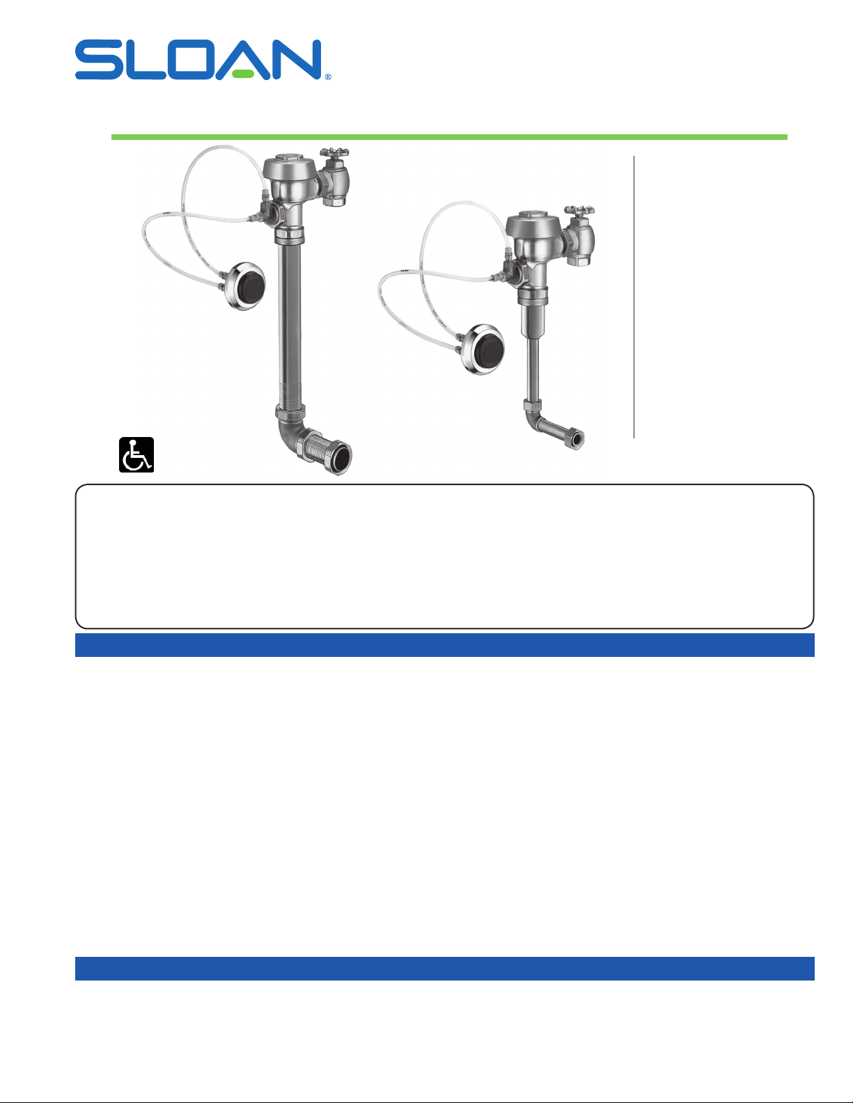
INSTALLATION INSTRUCTIONS FOR SLOAN SERIES 900 HYDRAULIC FLUSHING
SYSTEM — ROYAL® AND REGAL® XL CONCEALED CLOSET AND URINAL INSTALLATIONS
Concealed Closet Flushometer
1-1/2” (38 mm) Back Spud
MODEL 940
MODEL 952
Concealed Closet Flushometer
No-Flush Connection
MODEL 950
Concealed Closet Flushometer
1-1/2” (38 mm) Top Spud
MODEL 953
Concealed Urinal Flushometer
1-1/4” (32 mm) Back Spud
MODEL 990
Concealed Urinal Flushometer
3/4” (19 mm) Back Spud
Model 952
Model 995
MODEL 995
Rev. 5 (10/17)
LIMITED WARRANTY
Unless otherwise noted, Sloan Valve Company warrants this product, manufactured and sold for commercial or industrial uses, to be free from defects in material and
workmanship for a period of three (3) years (one (1) year for special finishes, SF faucets, PWT electronics and 30 days for PWT software) from date of first purchase. During
this period, Sloan Valve Company will, at its option, repair, replace, or refund the purchase price of any product which fails to conform with this warranty under normal use
and service. This shall be the sole and exclusive remedy under this warranty. Products must be returned to Sloan Valve Company, at customer’s cost. No claims will be
allowed for labor, transportation or other costs. This warranty extends only to persons or organizations who purchase Sloan Valve Company’s products directly from Sloan
Valve Company for purpose of resale. This warranty does not cover the life of the batteries.
THERE ARE NO WARRANTIES WHICH EXTEND BEYOND THE DESCRIPTION ON THE FACE HEREOF. IN NO EVENT IS SLOAN VALVE
COMPANY RESPONSIBLE FOR ANY CONSEQUENTIAL DAMAGES OF ANY MEASURE WHATSOEVER.
PRIOR TO INSTALLATION
Prior to installing the Sloan Flushometer, install the items listed below as
illustrated in the Rough-in Diagrams on Pages 2 and 3.
• Bore a 2” (51 mm) hole in wall for piping, if required.
• Install closet or urinal xture.
• Install 1-1/2” (38 mm) drain line (NOT supplied by Sloan).
• Install water supply line.
• Bore a 1-1/2” (38 mm) hole in wall for Hydraulic Push Button Actuator.
• For Model HY-72-A Push Button Actuator, install an electrical box at the
Push Button Actuator location.
NOTE: MAXIMUM DISTANCE FROM BUTTON TO VALVE IS 20’
(LONGER TUBING REQUIRED)
Important:
• INSTALL ALL PLUMBING IN ACCORDANCE WITH APPLICABLE
CODES AND REGULATIONS.
• WATER SUPPLY LINES MUST BE SIZED TO PROVIDE AN ADEQUATE
VOLUME OF WATER FOR EACH FIXTURE.
• FLUSH ALL WATER LINES PRIOR TO MAKING CONNECTIONS.
Sloan Royal and Regal XL Flushometers are designed to operate with 15
to 80 psi (103 to 552 kPa) of water pressure. THE MINIMUM PRESSURE
REQUIRED TO THE VALVE IS DETERMINED BY THE TYPE OF
FIXTURE SELECTED. Consult xture manufacturer for minimum pressure
requirements.
Most Low Consumption water closets (1.6 gpf/6.0 Lpf) require a minimum
owing pressure of 25 psi (172 kPa).
IMPORTANT: With the exception of Control Stop Inlet, DO NOT use
pipe thread sealant or plumbing grease on valve components or
couplings!
Protect the chrome or special finish of this Flushometer — DO NOT
use toothed tools to install or service the valve. Also, see “Care and
Cleaning” section of this manual.
TOOLS REQUIRED FOR INSTALLATION
• Straight blade (athead) screwdriver
• 5/64” hex wrench
• Sloan A-50 Super-Wrench™, Sloan A-109 Plier Wrench or smooth jawed spud wrench
• Parker Tube Cutter (PTC)
Page 2
VALVE ROUGH-INS
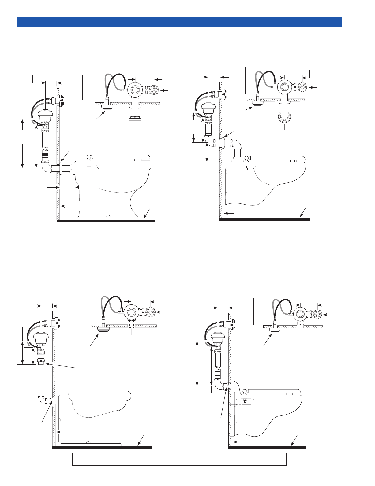
MODEL 940-1.6 — Low Consumption, 1.6 gpf (6.0 Lpf)
MODEL 940 — Water Saver, 3.5 gpf (13.2 Lpf)
1-1/2” (38 mm)
OPENING
2-1/4” (57 mm) MIN.
14-1/2”
(368 mm)
13”
(330 mm)
4” (102 mm)
IN WALL
PUSH BUTTON
(LOCATION
OPTIONAL)
2” (51 mm)
OPENING IN WALL
FIN. WALL
CENTERLINE
OF FIXTURE
(121 mm)
FIN.
FLOOR
4-3/4”
1” I.P.S.
(25 mm DN)
WATER
SUPPLY
MODEL 953-1.6 — Low Consumption, 1.6 gpf (6.0 Lpf)
MODEL 953 — Water Saver, 3.5 gpf (13.2 Lpf)
2-1/4”
(57 mm)
MIN.
9”
(229 mm)
7-1/2”
(191 mm)
5”
(127 mm)
1-1/2” (38 mm)
OPENING
IN WALL
PUSH BUTTON
(LOCATION
OPTIONAL)
2” (51 mm)
OPENING IN WALL
FIN. WALL
CENTERLINE
OF FIXTURE
4-3/4”
(121 mm)
1” I.P.S.
(25 mm DN)
WATER
SUPPLY
FIN.
FLOOR
MODEL 950-1.6 — Low Consumption, 1.6 gpf (6.0 Lpf)
MODEL 950 — Water Saver, 3.5 gpf (13.2 Lpf)
Note: Also for use with Flushing Rim Floor Drains and Squat Toilets.
Note: Valve can be located in ceiling above xture.
1-1/2” (38 mm)
OPENING
2-1/4” (57 mm) MIN.
3”
(76 mm)
1-1/2”
(38 mm)
2” (51 mm)
OPENING IN
WALL
IN WALL
PUSH BUTTON
(LOCATION
OPTIONAL)
1” FEMALE I.P.S.
(25 mm DN)
OUTLET
FIN. WALL
CENTERLINE
OF FIXTURE
F-22
FIN.
FLOOR
4-3/4”
(121 mm)
1” I.P.S.
(25 mm DN)
WATER
SUPPLY
MODEL 952-1.6 — Low Consumption, 1.6 gpf (6.0 Lpf)
MODEL 952 — Water Saver, 3.5 gpf (13.2 Lpf)
1-1/2” (38 mm)
OPENING
2-1/4” (57 mm) MIN.
14-1/2”
(368 mm)
13”
(330 mm)
2” (51 mm)
OPENING
IN WALL
IN WALL
PUSH BUTTON
(LOCATION
OPTIONAL)
FIN. WALL
CENTERLINE
OF FIXTURE
FLOOR
4-3/4”
(121 mm)
1” I.P.S.
(25 mm DN)
WATER
SUPPLY
FIN.
Note: Water Closet Valves with “-2.4” Model Designation deliver 2.4 gpf (9.0 Lpf).
2
Page 3
VALVE ROUGH-INS (CONTINUED)
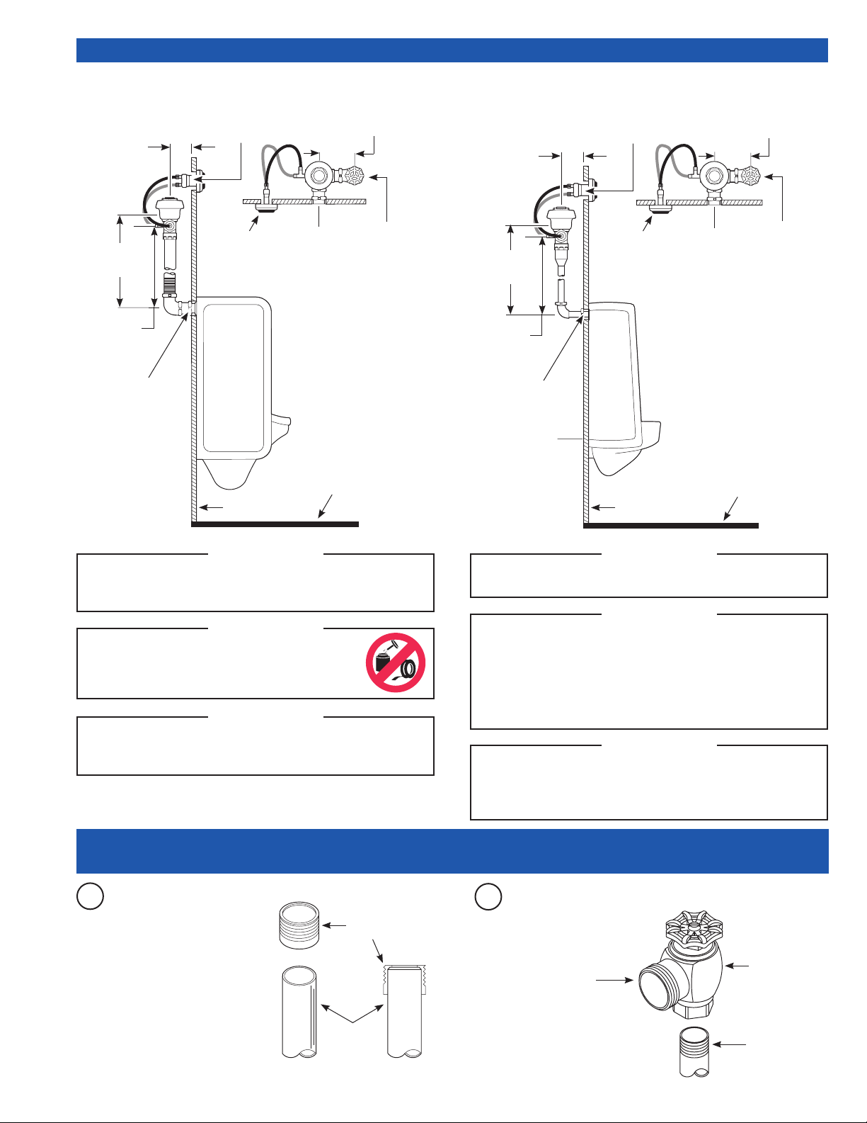
MODEL 990-1.0 — Low Consumption, 1.0 gpf (3.8 Lpf)
MODEL 990-1.5 — Water Saver, 1.5 gpf (5.7 Lpf)
MODEL 990 — Standard, 3.5 gpf (13.2 Lpf)
1-1/2” (38 mm)
2-1/4”
(57 mm)
MIN.
OPENING IN WALL
4-3/4”
(121 mm)
MODEL 995-0.5 — 0.5 gpf (1.9 Lpf)
MODEL 995-1.0 — Low Consumption, 1.0 gpf (3.8 Lpf)
MODEL 995 — Water Saver, 1.5 gpf (5.7 Lpf)
1-1/2” (38 mm)
2-1/4”
(57 mm)
MIN.
OPENING IN WALL
4-3/4”
(121 mm)
1” I.P.S.
(25 mm DN)
WATER
SUPPLY
FIN.
14-1/2”
(368 mm)
13”
(330 mm)
2” (51 mm)
OPENING IN WALL
PUSH BUTTON
(LOCATION
OPTIONAL)
FIN. WALL
!!! IMPORTANT !!!
CENTERLINE
OF FIXTURE
FLOOR
Carefully read this manual to ensure proper product
installation and longevity. Also, please visit our website www.sloan.com to
download our most recent documentation for this product.
!!! IMPORTANT !!!
With the exception of the Control Stop Inlet,
do NOT use pipe thread sealant or plumbing grease on valve
components or couplings.
!!! IMPORTANT !!!
This product contains mechanical and/or electrical components that are subject
to normal wear. These components should be checked on a regular basis and
replaced as needed to maintain the valve’s performance.
3/4” I.P.S.
(20 mm DN)
WATER
SUPPLY
FIN.
FLOOR
13-1/2”
(343 mm)
12”
(305 mm)
2” (51 mm)
OPENING IN WALL
PUSH BUTTON
(LOCATION
OPTIONAL)
FIN. WALL
!!! IMPORTANT !!!
CENTERLINE
OF FIXTURE
When ordering, specify the model variation required. Note: Water Closet Valves
with “-2.4” Model Designation deliver 2.4 gpf (9.0 Lpf).
!!! IMPORTANT !!!
Protect the chrome or special nish of Sloan Flushometers. Do NOT use toothed
tools to install or service valves. Use a Sloan A-50 Super Wrench™,
Sloan A-109 Plier Wrench or smooth jawed spud wrench to secure couplings.
See “Care and Cleaning” section of this manual.
Never open the Control Stop to where the ow from the valve exceeds the ow
capability of the xture. In the event of a valve failure, the xture must be able
to accommodate a continuous ow from the valve.
!!! IMPORTANT !!!
If you have questions about how to install your Sloan Flushometer, consult
your local Sloan Representative, or call the Sloan Installation Engineering
Department at:
1-888-SLOAN-14 (1-888-756-2614)
1- INSTALL OPTIONAL SWEAT SOLDER ADAPTER (ONLY IF YOUR SUPPLY PIPE DOES
NOT HAVE A MALE THREAD) AND INSTALL CONTROL STOP
For Sweat Solder applications,
A
slide Threaded Adapter onto
water supply pipe until end
of pipe rests against shoulder
of Adapter. Sweat solder the
Adapter to water supply pipe.
THREADED
ADAPTER
WATER
SUPPLY
PIPE
3
Install the Sloan Bak-
B
Chek
®
Control Stop to
the water supply line with
the outlet positioned as
required.
OUTLET
BAK-CHEK®
CONTROL STOP
IRON PIPE NIPPLE
OR COPPER PIPE
WITH SWEAT
SOLDER ADAPTER
Page 4
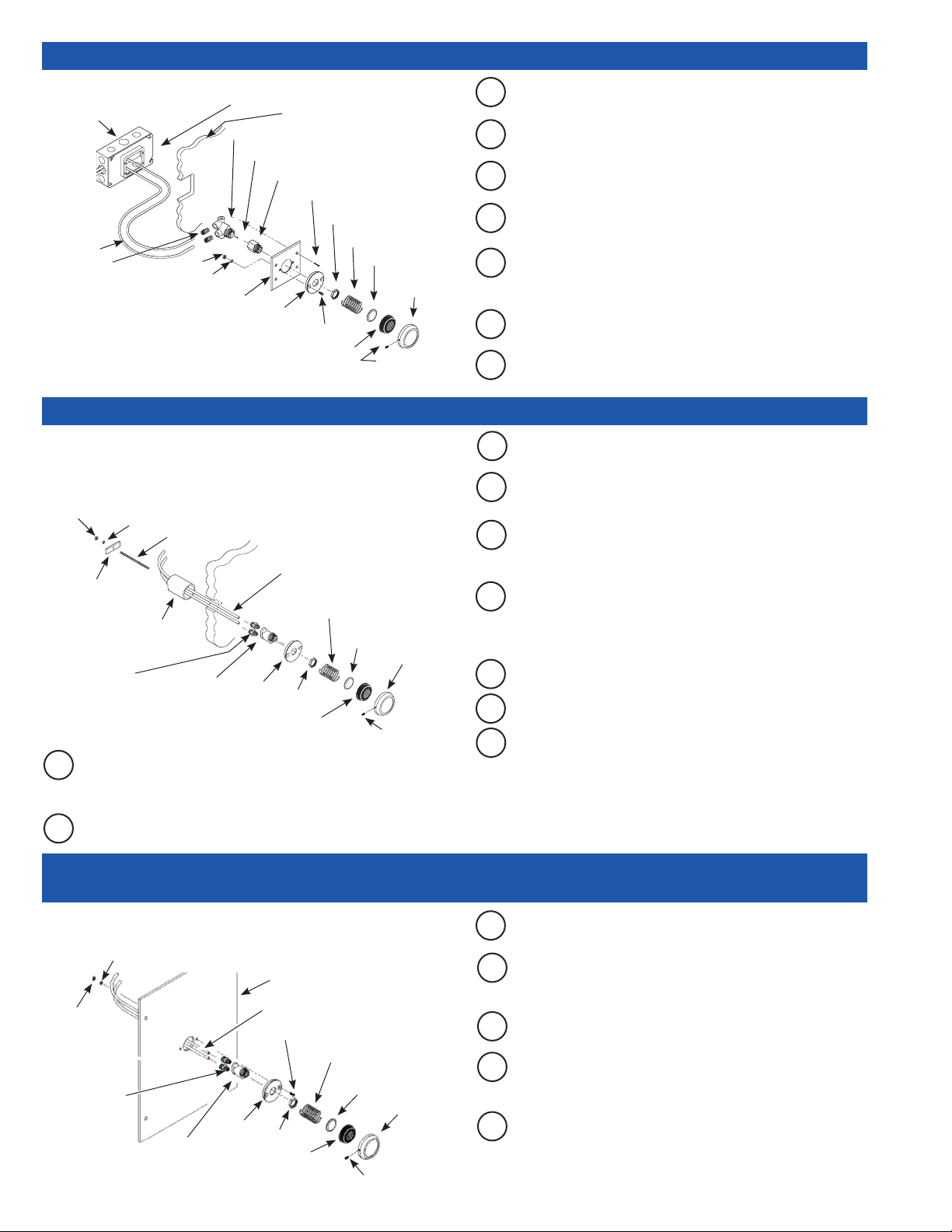
2A - INSTALL HY-72-A SIDE WALL (SW VARIATION) PUSH BUTTON ACTUATOR
UNIVERSAL
(2) GANG
ELEC. BOX
1-5/8” D x
4-1/2” H x
6-13/16”
W (NOT
SUPPLIED
BY SLOAN)
PLASTIC
TUBING
CONNECT
FITTINGS (2)
QUICK
(2) GANG ELEC. BOX DEVICE COVER 3/4” RAISED
x 4-3/4” H x 7-1/16” W (NOT SUPPLIED BY SLOAN)
WALL
ACTUATOR
EXTENSION STEM
EXTENSION ADAPTER
COVER PLATE SCREWS (4)
NUT
NUTS (2)
LOCKWASHERS (2)
COVER PLATE
WALL FLANGE
FLATHEAD SCREWS (2)
PUSH BUTTON
SPRING
BRASS INSERT
BUTTON
FLANGE
SETSCREW
Mount Wall Flange onto Cover Plate using (2) Flathead Screws,
A
Lockwashers and Nuts provided. Tighten Fasteners securely.
Insert Extension Stem into Extension Adapter and thread Extension
B
Adapter onto Push Button Actuator.
Insert threaded end of Push Button Actuator Assembly through
C
Cover Plate Assembly. Fasten to Plate with Nut. Tighten securely.
Place Brass Insert into black Push Button. Concave side of Brass
D
Insert must face outward of Push Button.
E
Insert black Push Button into Button Flange. Place Spring against
Brass Insert of Push Button. Install Push Button Assembly onto
Wall Flange. Secure with Setscrew located on Button Flange.
Attach Plastic Tubing. See: Steps to Attach Plastic Tubing (Page 5).
F
Mount Cover Plate Assembly onto electrical box cover using the
G
four (4) Screws provided.
2B - INSTALL HY-33-A FIXTURE WALL (FW VARIATION) PUSH BUTTON ACTUATOR
Note: The HY-33-A Fixture Wall may be installed directly onto xture wall
where access behind wall is available. If rear access is not available,
HY-33-A may be installed onto a Sloan Easy Access Wall Box Assembly.
Parts for both installations are included with the HY-33-A Push Button.
NUT
RETAINING
BAR
SPACER SLEEVE —
USE ONLY IF WALL
THICKNESS IS LESS
FITTINGS (2)
A
LOCKWASHER
THREADED
ROD
PLASTIC TUBING
WALL
SPRING
BRASS
INSERT
THAN 2” (51 mm)
QUICK
CONNECT
PUSH BUTTON
ACTUATOR
WALL
FLANGE
NUT
PUSH BUTTON
BUTTON
FLANGE
SETSCREW
If not already completed, bore a 1-1/2” (38 mm) diameter hole in
wall for the Push Button Actuator. Refer to the Rough-in drawings
on Pages 2 and 3.
B
Screw Threaded Rod into back of Push Button Actuator.
Insert threaded end of Push Button Actuator into Wall Flange and
C
install Nut. Tighten Nut securely.
D
Place Brass Insert into black Push Button. Concave side of Brass
Insert must face outward of Push Button.
E
Insert black Push Button into Button Flange. Place Spring against
Brass Insert of Push Button. Install Push Button Assembly onto
Wall Flange. Secure with Setscrew located on Button Flange.
F
If Spacer Sleeve is required, from behind wall, run Plastic Tubing
through Sleeve (notched end of Sleeve toward rear) and through
Wall. Spacer Sleeve is only required if wall thickness is less than
2” (51 mm).
Attach Plastic Tubing. See: Steps to Attach Plastic Tubing (Page 5).
G
H
Insert Push Button Assembly into the 1-1/2” (38 mm) wall hole.
I
From behind wall, slide Spacer Sleeve (if required) over Threaded
Rod and rest it against rear of wall. Slide Retaining Bar onto
Threaded Rod and into slots of Sleeve (if required), or against wall
if Sleeve is not required. Install Lockwasher and Nut onto Threaded
Rod. Tighten securely. Carefully cut excess Threaded Rod, making
certain to not damage Plastic Tubing.
2C - INSTALL HY-33-A FIXTURE WALL (FW VARIATION) WITH WALL BOX PUSH BUTTON
ACTUATOR
Note: Sloan WB-1-A easy access wall box is designed for use with
HY-33-A and HY-108-A Actuators.
LOCKWASHERS (2)
WALL BOX COVER PLATE
NUTS (2)
QUICK CONNECT
FITTINGS (2)
PUSH
BUTTON
ACTUATOR
WALL
FLANGE
PLASTIC TUBING
FLATHEAD SCREWS (2)
NUT
PUSH BUTTON
SPRING
BRASS
INSERT
SETSCREW
BUTTON
FLANGE
A
Insert threaded end of Push Button Actuator through Wall Flange
and install Nut. Tighten Nut securely.
B
Mount Wall Flange and Push Button Actuator to Wall Box Cover
Plate using Flathead Screws, Lockwashers and Nuts provided.
Tighten fasteners securely.
Place Brass Insert into black Push Button. Concave side of Brass
C
Insert must face outward of Push Button.
D
Insert black Push Button into Button Flange. Place Spring against
Brass Insert of Push Button. Install Push Button Assembly onto
Wall Flange. Secure with Setscrew located on Button Flange.
E
Attach Plastic Tubing. See: Steps to Attach Plastic Tubing (Page 5).
4
Page 5
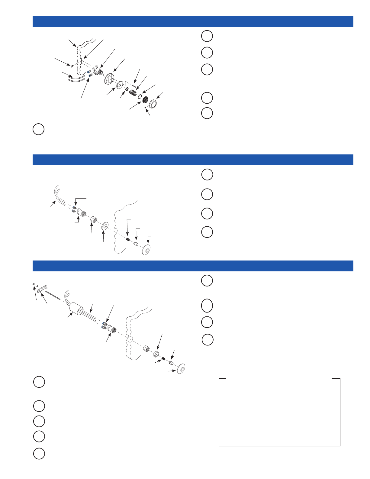
2D - INSTALL HY-49-A METAL PARTITION (MP VARIATION) PUSH BUTTON ACTUATOR
METAL
PARTITION
CLIP
NUTS (2)
COVER PLATE
MOUNTING HOLE
PUSH BUTTON ACTUATOR
COVER PLATE
Insert threaded end of Push Button Actuator through Cover Plate
B
and Wall Flange and install Nut. Tighten Nut securely.
Attach Plastic Tubing. See: Steps to Attach Plastic Tubing (below).
C
PLASTIC
TUBING
WALL
QUICK CONNECT
FITTINGS (2)
Using Cover Plate as a template, drill two 3/16” (5 mm) Cover
A
FLANGE
PUSH BUTTON
FLATHEAD SCREWS (2)
NUT
SPRING
BRASS INSERT
SETSCREW
BUTTON
FLANGE
Insert Flathead Screws through Wall Flange and Cover Plate
D
mounting holes. Mount Wall Flange and Cover Plate to metal
partition using Flathead Screws provided. Tighten fasteners
securely.
Place Brass Insert into black Push Button. Concave side of Brass
E
Insert must face outward of Push Button.
Insert black Push Button into Button Flange. Place Spring against
F
Brass Insert of Push Button. Install Push Button Assembly onto
Wall Flange. Secure with Setscrew located on Button Flange.
Plate Mounting holes and cut opening for Push Button Actuator
into the metal partition. Install Clip Nuts with threaded side toward
back.
2E - INSTALL HY-108-A METAL BUTTON – PANEL MOUNT (MBPM VARIATION)
Note: Use HY-108-A (MBPM) on punched stainless steel plates
and security xtures with front access.
QUICK
PLASTIC
TUBING
PUSH BUTTON
ACTUATOR
ACTUATOR
ASSEMBLY NUT
CONNECT
FITTINGS (2)
PANEL
SPRING
METAL BUTTON
WASHER
BUTTON FLANGE
Attach Plastic Tubing to Push Button Actuator. See: Steps to Attach
A
Plastic Tubing (below).
Thread Actuator Assembly Nut onto threaded end of Push Button
B
Actuator.
Slide Spring over Metal Push Button until it snaps into place.
C
Insert Metal Push Button into Button Flange.
From front of panel, insert Button Flange Assembly into hole of
D
panel. Behind panel, place Washer over threads of Button Flange.
Thread Button Flange onto Actuator. Tighten Flange securely.
2F - INSTALL HY-100-A METAL BUTTON – FIXTURE WALL (MBFW VARIATION)
Note: Behind wall access required to install HY-100-A (MBFW)
LOCKWASHER
NUT
RETAINING
BAR
SPACER SLEEVE —
USE ONLY IF WALL
THICKNESS IS LESS
THAN 2” (51 mm)
If not already completed, bore a 1-1/2” (38 mm) diameter hole in
A
THREADED ROD
PLASTIC
TUBING
PUSH
BUTTON
ACTUATOR
QUICK
CONNECT
FITTINGS (2)
ACTUATOR
ASSEMBLY
NUT
WALL
SPRING
BUTTON FLANGE
wall for the Push Button Actuator. Refer to the Rough-in drawings
on Pages 2 and 3.
Screw Threaded Rod into back of Push Button Actuator.
B
Thread Actuator Assembly Nut onto end of Push Button Actuator.
C
Slide Spring over Metal Push Button until it snaps into place.
D
Insert Metal Push Button into Button Flange.
SPACER
RING
METAL
BUTTON
F
From behind wall, run Plastic Tubing through optional Spacer
Sleeve (notched end of sleeve toward rear) and wall. Spacer
Sleeve only required if wall thickness is less than 2” (51 mm).
Attach Plastic Tubing. See: Steps to Attach Plastic Tubing (below).
G
Insert Push Button Assembly into the 1-1/2” (38 mm) wall hole.
H
From behind wall, slide Spacer Sleeve (if required) over Threaded
I
Rod and rest it against rear of wall. Slide Retaining Bar onto
Threaded Rod and into slots of Sleeve (if required), or against wall
if Sleeve is not required. Install Lockwasher and Nut onto Threaded
Rod. Tighten securely. Carefully cut excess Threaded Rod, making
certain to not damage Plastic Tubing.
STEPS TO ATTACH PLASTIC TUBING
(1) The Push Button Actuator is connected to the Flushometer
Body by two Plastic Tubes, Yellow and Blue. Match color
of the Tubes to color on the Actuator.
(2) Cut off excess Plastic Tubing leaving 3” to 4”
(76 to 102 mm) of slack when Push Button Actuator is
installed.
(3) Slide plastic tubing into its corresponding valve actuator
tting. Pull tubing to make sure connection is secure.
(tubing can be removed by pressing on blue/yellow
connection button to release.)
E
Place Spacer Ring over threads of Button Flange and thread
Button Flange Assembly into Actuator Assembly Nut.
5
Page 6
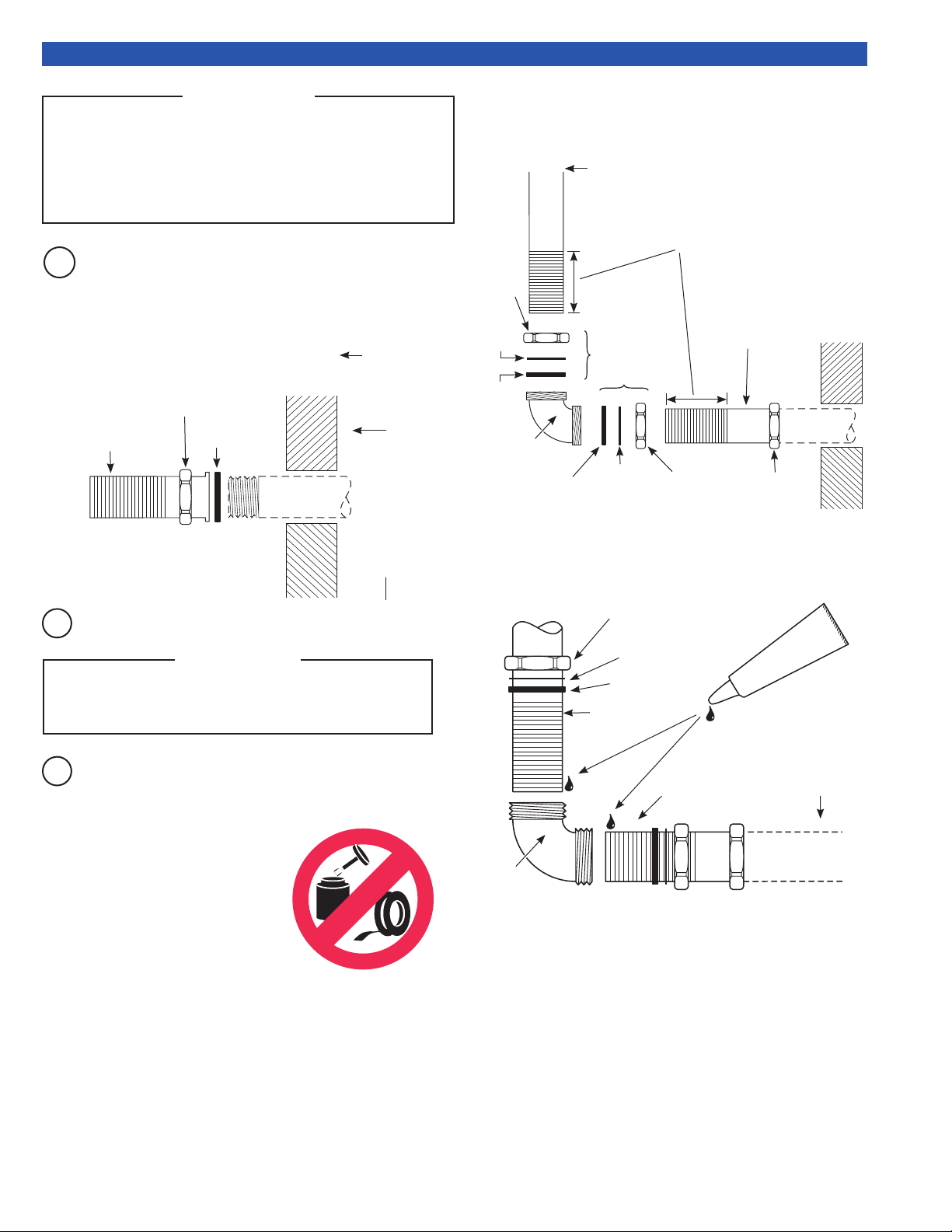
3- INSTALL VACUUM BREAKER FLUSH CONNECTION
NOTE
Sloan Prison Flushometers are designed to connect to a stainless
steel prison fixture in the chase behind the wall. A 1-1/2” (38 mm)
pipe connection (NOT supplied by Sloan) must be used to connect
the fixture inlet from the wall to the flush connection. For urinals
using a Model 613 or 9613 valve, a 3/4” (19 mm) pipe connection
must be used to connect the fixture inlet from the wall to the flush
connection.
Secure anged end of F-100 Flush Connection to the 1-1/2”
A
(38 mm) pipe using a 1-1/2” F-2-A Coupling Nut with S-21 Gasket.
Tighten securely.
For urinals using a Model 613 or 9613 Valve, secure anged
end of F-15-A Flush Connection to the 3/4” (19 mm) pipe using a
3/4” F-2-AW slip joint coupling (Rubber Gasket, Nylon Slip Gasket and
Coupling Nut). Tighten securely.
F-2-A
COUPLING NUT
F-100 FLUSH CONNECTION*
(SUPPLIED 3-1/4” LONG)
Cut Vacuum Breaker and Flush Connection tubes to length.
B
S-21 GASKET
!!! IMPORTANT !!!
FIXTURE SIDE
OF WALL
1-1/2”OR 3/4”
I.P.S. PIPE
CONNECTION
(NOT SUPPLIED
BY SLOAN)
IMPORTANT: WHEN CUTTING SCORED TUBES TO
FIT, ALWAYS KEEP AT LEAST 1-1/4” (32 MM) OF
SCORING TO ASSURE PROPER ENGAGEMENT
WITH COMPRESSION COUPLING.
Slide the Coupling Nut, Nylon Slip Gasket and Rubber Gasket onto
C
the Vacuum Breaker and Flush Connection tubes.
Install Slip Elbow (Figure 2)
Connect scored ends of vacuum breaker tube and F-100/F-102 ush
connection to the elbow using coupling, slip gasket and rubber compression
gasket. After applying Loctite® to scored ends, tighten securely.
VACUUM
COUPLING
NUT
NYLON
SLIP
GASKET
RUBBER
GASKET
ELBOW
Figure 2
RUBBER
GASKET
BREAKER
SLIP JOINT
COUPLING
NYLON
SLIP
GASKET
IMPORTANT: WHEN CUTTING SCORED
TUBES TO FIT, ALWAYS KEEP AT
LEAST 1-1/4” (32 mm) OF SCORING TO
ASSURE PROPER ENGAGEMENT WITH
COMPRESSION COUPLING.
F-100 FLUSH
CONNECTION
COUPLING
NUT
F-2-A
COUPLING NUT
IMPORTANT: Before inserting the scored ends into the Elbow,
apply several drops of Loctite (supplied by Sloan) to the scored
ends of the tubes (Figure 3). This sealant helps prevent separation
under high-pressure conditions. DO NOT use any other pipe
sealant or lubricant on this connection.
COUPLING
NUT
NYLON
SLIP
GASKET
RUBBER
GASKET
VACUUM
BREAKER
Apply Loctite to
scored ends of
tubes
F-100 FLUSH CONNECTION
1-1/2” OR
3/4” I.P.S. PIPE
CONNECTION
(NOT SUPPLIED
BY SLOAN)
6
ELBOW
Figure 3
Loctite can also be used to secure Push Button Flange. See
Sealant package for details.
Page 7
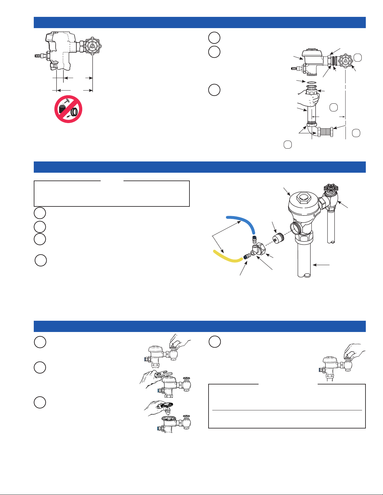
4 - INSTALL FLUSHOMETER
Maximum adjustment of Sloan Adjustable
Tailpiece is 1/2” (13 mm) IN or OUT from
the standard 4-3/4” (121 mm) (centerline
of Flushometer to centerline of Control
Stop). If rough-in measurement exceeds
5-1/4” (133 mm), consult factory for longer
4-1/4”
(108 mm)
5-1/4”
(133 mm)
MIN.
MAX.
tailpiece.
IMPORTANT: Use a Sloan A-50 Super-
Wrench™, Sloan A-109 Plier Wrench
or smooth jawed spud wrench to secure
all couplings. This will eliminate damage
to chrome or special nish that normally
occurs when slip-joint pliers, pipe wrenches
or other “toothed” tools are used.
5 - INSTALL VALVE ACTUATOR
NOTE
TUBING MUST BE CONNECTED TO PROPER VALVE ACTUATOR. YELLOW
TUBE MUST BE CONNECTED TO YELLOW/”O” FITTING AND BLUE TUBE
MUST BE CONNECTED TO BLUE/”L” FITTING.
Insert Actuator Cartridge into Flushometer Valve Body.
A
Install Valve Actuator Housing onto Flushometer Valve Body.
B
Tighten Housing Nut with a wrench.
C
Cut excess Tubing so that there will be 3” to 4” (76 to 102 mm) of
slack when connected to Valve Actuator.
PLASTIC
TUBING
Insert Adjustable Tailpiece into Control Stop. Lubricate O-ring seal
A
with water. Hand tighten Tailpiece Coupling.
Align Flushometer
B
Body on top of
FLUSHOMETER
BODY
Vacuum Breaker
Flush Connection.
Hand tighten Vacuum
Breaker Coupling.
Align Flushometer
C
Body. Using a wrench,
securely tighten
couplings in order
given: (1) Tailpiece
Coupling, (2) Vacuum
Breaker Coupling, (3)
Slip Joint Couplings
and (4) Spud Coupling.
FLUSHOMETER VALVE BODY
HY-83-A
ACTUATOR
CARTRIDGE
G-44
FRICTION
RING
VACUUM
BREAKER
FLUSH
CONNECTION
WITH
REPAIR KIT
SLIP JOINT
COUPLINGS
3
C/L
FIXTURE
O-RING
ADJUSTABLE
TAILPIECE
VACUUM
BREAKER
COUPLING
2
4-3/4”
(121 mm)
TAILPIECE
COUPLING
1
CONTROL
STOP
SPUD
COUPLING
4
C/L
SUPPLY
BAK-CHEK®
CONTROL STOP
Slide colored plastic tubing into its corresponding colored valve
D
actuator tting. Pull tubing to make sure connection is secure.
(Tubing can be removed by pressing on blue/yellow connection
button to release.)
QUICK CONNECT FITTINGS
(2)
6 - FLUSH OUT SUPPLY LINE AND ADJUST CONTROL STOP
Adjust Control Stop to meet ow rate
A
Shut off Control Stop by turning handle
CLOCKWISE. Then remove Flushometer
Cover.
Lift out the inside Parts Assembly as
B
a complete unit. Reinstall Flushometer
Cover and tighten with wrench. Open
Control Stop. Turn on water supply to
ush line of any debris or sediment.
Shut off Control Stop and remove
C
Flushometer Cover. Reinstall Inside Parts
Assembly and Flushometer Cover. Tighten
Cover with wrench. Open Control Stop and
activate Flushometer Valve.
D
required for proper cleansing of xture.
Open Control Stop COUNTERCLOCKWISE
ONE FULL turn from closed position.
Activate Flushometer. Adjust Control Stop
after each ush until the rate of ow
delivered properly cleanses the xture.
Sloan Flushometers are engineered for quiet operation. Excessive water ow creates
noise, while too little water ow may not satisfy the needs of the xture. Proper
adjustment is made when the plumbing xture is cleansed after each ush without
splashing water out from the lip AND a quiet ushing cycle is achieved.
Never open Control Stop to where the ow from the valve exceeds the ow capability
of the xture. In the event of a valve failure, the xture must be able to accommodate
a continuous ow from the valve.
HOUSING
NUT
VALVE ACTUATOR
HOUSING
!!! IMPORTANT !!!
VACUUM
BREAKER
TUBE
7
Page 8

CARE AND CLEANING
DO NOT USE abrasive or chemical cleaners (including chlorine bleach) to clean Flushometers that may dull the luster and attack the chrome or special
decorative nishes. Use ONLY mild soap and water, then wipe dry with clean cloth or towel.
While cleaning the bathroom tile, protect the Flushometer from any splattering of cleaner. Acids and cleaning uids will discolor or remove chrome plating.
TROUBLESHOOTING
Push Button Actuator Assembly
1. Push Button Leaks.
The actuator cartridge has an accumulation of lime or its seals are damaged or worn.
Replace with a new HY-32-A cartridge.
2. The Flushometer does not ush and a small amount of leakage is visible below the
valve.
A. Foreign material lodged in the cartridge. Remove the cartridge and inspect for
foreign material. Clean under running water.
B. The actuator cartridge has an accumulation of lime or its seals are damaged or
worn. Replace with a new HY-32-A cartridge.
C. Plastic Tubing is installed incorrectly. Install Plastic Tubing correctly
(see Steps 2 and 5).
ACTUATOR CARTRIDGE REMOVAL
Plastic Push Button Actuator Removal:
(1) Loosen the setscrew in the button ange and remove the button, ange, and
spring from the actuator body.
(2) Unscrew the cartridge from the actuator body.
Metal Push Button Actuator Removal:
(1) Remove the button or actuator assembly from the wall or xture.
(2) Disassemble the ange or button assembly from the actuator body.
(3) Unscrew the cartridge from the actuator body.
NOTE: The metal Push Button is designed to be vandal-proof and must be
removed from the wall or xture for service.
Flushometer Actuator Assembly
1. The Flushometer does not ush or ushes only once and will not ush a second
time when the button is pushed.
A. The plunger is lodged in the actuator cartridge or the plunger bypass hole is
clogged. Remove actuator housing and cartridge from the Flushometer. Clean
under running water. If cartridge parts are worn, deteriorated or limed up and
problem persists after cleaning, replace with a new HY-83-A cartridge.
B. Plastic Tubing is installed incorrectly. Install Plastic Tubing correctly
(see Steps 2 and 5).
REMOVAL OF THE ACTUATOR FROM THE FLUSHOMETER:
(1) Turn off water at the Control Stop.
(2) Unscrew the actuator housing coupling nut from the Flushometer.
(3) Remove the actuator housing from the Flushometer. The tubing connections can
be left intact.
(4) Carefully remove the actuator cartridge from the Flushometer body to prevent
the actuator from abrupt separation due to expansion of an internal spring. If
the actuator cartridge is lodged in the Flushometer body cavity, gently grip the
exposed portion of the cartridge with a channel-lock pliers and rotate back and
forth to loosen the O-ring seal.
(5) Carefully separate the actuator housing to reveal the spring and plunger.
Flushometer Service
1. Flushometer does not function (no flush).
A. Control Stop or Main Valve is Closed. Open Control Stop or Main Valve.
B. Relief Valve is worn. Replace Royal Performance Kit (Royal Flushometers) or
Inside Parts Kit (Regal XL Flushometers).
2. Volume of water is not sufficient to siphon fixture.
A. Control Stop is not open wide enough. Adjust Control Stop for desired delivery of
water volume.
B. Urinal Flushometer parts installed in a Closet Flushometer. Replace inside Urinal
Flushometer parts with proper Closet Flushometer parts.
C. Incorrect Dual Filtered Diaphragm Assembly (Royal Flushometers) or Inside
Parts Kit (Regal XL Flushometers) is installed in Flushometer; for instance, Urinal
assembly inside a Closet Flushometer, or Low Consumption assembly inside a
higher consumption xture. Determine the ush volume required by the xture
and replace Royal Performance Kit or Inside Parts Kit. Use valve label and
markings on xture for reference.
D. Water supply volume or pressure is inadequate. If no gauges are available to
properly measure supply pressure or volume of water at the Flushometer, then
remove the Relief Valve from the Dual Filtered Diaphragm Assembly (Royal
Flushometers) or Inside Parts Kit (Regal XL Flushometers), reassemble the
Flushometer and completely open the Control Stop. If the xture siphons, more
water volume is required.
For Royal Flushometers — Install a higher ushing volume Royal
Performance Kit.
For Regal XL Flushometers — If a 3.5 gpf Inside Parts Kit is installed in the
8
Flushometer, then rst ip the Rell Head (under the Diaphragm) to obtain a
4.5 gpf volume. If this volume is still inadequate, remove the Flow Ring from
the Guide to obtain a 6.5 gpf Kit. If additional ow is still required, try a Low
Pressure Guide Kit A-175-A (#0301104).
IMPORTANT — Laws and Regulations requiring Low Consumption
Fixtures (1.6 gpf/6.0 Lpf Water Closets and 1.0 gpf/3.8 Lpf Urinals)
prohibit the use of higher flushing volumes.
If the xture does not siphon or if a Low Consumption ush is required, steps
must be taken to increase the water supply pressure and/or volume. Contact the
xture manufacturer for minimum water supply requirements of the xture.
3. Flushometer closes off immediately.
A. Ruptured or damaged diaphragm. Replace Royal Performance Kit (Royal
Flushometers) or Inside Parts Kit (Regal XL Flushometers).
B. For Regal XL Flushometers — An enlarged bypass orice from corrosion or
damage. Replace Inside Parts Kit.
4. Length of flush is too short (Short Flush).
A. For Regal Flushometers — The Diaphragm Assembly and Guide Assembly are
not hand tight. Screw the two assemblies hand tight.
B. For Regal XL Flushometers — An enlarged bypass orice from corrosion or
damage. Replace Inside Parts Kit.
C. Dual Filtered Diaphragm Assembly (Royal Flushometers) or Inside Parts Kit
(Regal XL Flushometers) is damaged. Replace Royal Performance Kit or Inside
Parts Kit.
D. Incorrect Dual Filtered Diaphragm Assembly (Royal Flushometers) or Inside
Parts Kit (Regal XL Flushometers) is installed in Flushometer; for instance, Urinal
assembly inside a Closet Flushometer, or Low Consumption assembly inside a
higher consumption xture. Determine the ush volume required by the xture
and replace Royal Performance Kit or Inside Parts Kit. Use valve label and
markings on xture for reference.
5. Length of flush is too long (Long Flush) or continuous.
A. For Royal Flushometers — Metering bypass hole in Diaphragm is clogged.
Remove the Dual Filtered Diaphragm Assembly. Remove the Primary and
Secondary Filter Rings from the Diaphragm and wash under running water.
Replace Royal Performance Kit if cleaning does not correct the problem.
B. For Regal XL Flushometers — Relief Valve (A-19-A) is not seating properly or
bypass orice is clogged. Disassemble the working parts and wash thoroughly.
NOTE: SIZE OF THE ORIFICE IN THE BYPASS IS OF UTMOST IMPORTANCE
FOR THE PROPER METERING OF WATER INTO THE UPPER CHAMBER
OF THE FLUSHOMETER. DO NOT ENLARGE OR DAMAGE THIS ORIFICE.
REPLACE INSIDE PARTS KIT IF CLEANING DOES NOT CORRECT PROBLEM.
C. Supply line water pressure has dropped and is not sufcient to close the valve.
Close Control Stop until pressure is restored.
D. Dual Filtered Diaphragm Assembly (Royal Flushometers) or Inside Parts Kit
(Regal XL Flushometers) is damaged. Replace Royal Performance Kit or Inside
Parts Kit.
E. Incorrect Dual Filtered Diaphragm Assembly (Royal Flushometers) or Inside
Parts Kit (Regal XL Flushometers) is installed in Flushometer; for instance, Urinal
assembly inside a Closet Flushometer, or Low Consumption assembly inside a
higher consumption xture. Determine the ush volume required by the xture
and replace Royal Performance Kit or Inside Parts Kit. Use valve label and
markings on xture for reference.
F. White Closet Relief Valve has been used in a Urinal Flushometer. Replace Closet
Relief Valve (A-19-AC) with Black Urinal Relief Valve (A-19-AU).
G. Inside Cover is cracked or damaged. Replace the Inside Cover (A-71).
H. Conditions in the piping system may contribute to the noise. A degree of high
pressure in the piping may be relieved by adjustments to Control Stop. Other
noises created by loose pipes, lack of air chambers, inadequate pipe sizes, etc.,
are problems that must be discussed with the building engineer.
6. Chattering noise is heard during flush.
A. Inside Cover is damaged. Replace Inside Cover (A-71).
B. For Regal XL Flushometers — A-156-A Segment Diaphragm has been installed
upside-down. Reposition the Segment Diaphragm properly (see markings on the
Diaphragm).
For more information concerning Royal and Regal XL Flushometers, consult
Sloan Hydraulic Valve Repair and Maintenance guides. You may also wish
to contact your local Sloan Representative. If further assistance is required,
please contact the Sloan Valve Company Installation Engineering Department
at: 1-888-SLOAN-14 (1-888-756-2614)
Page 9
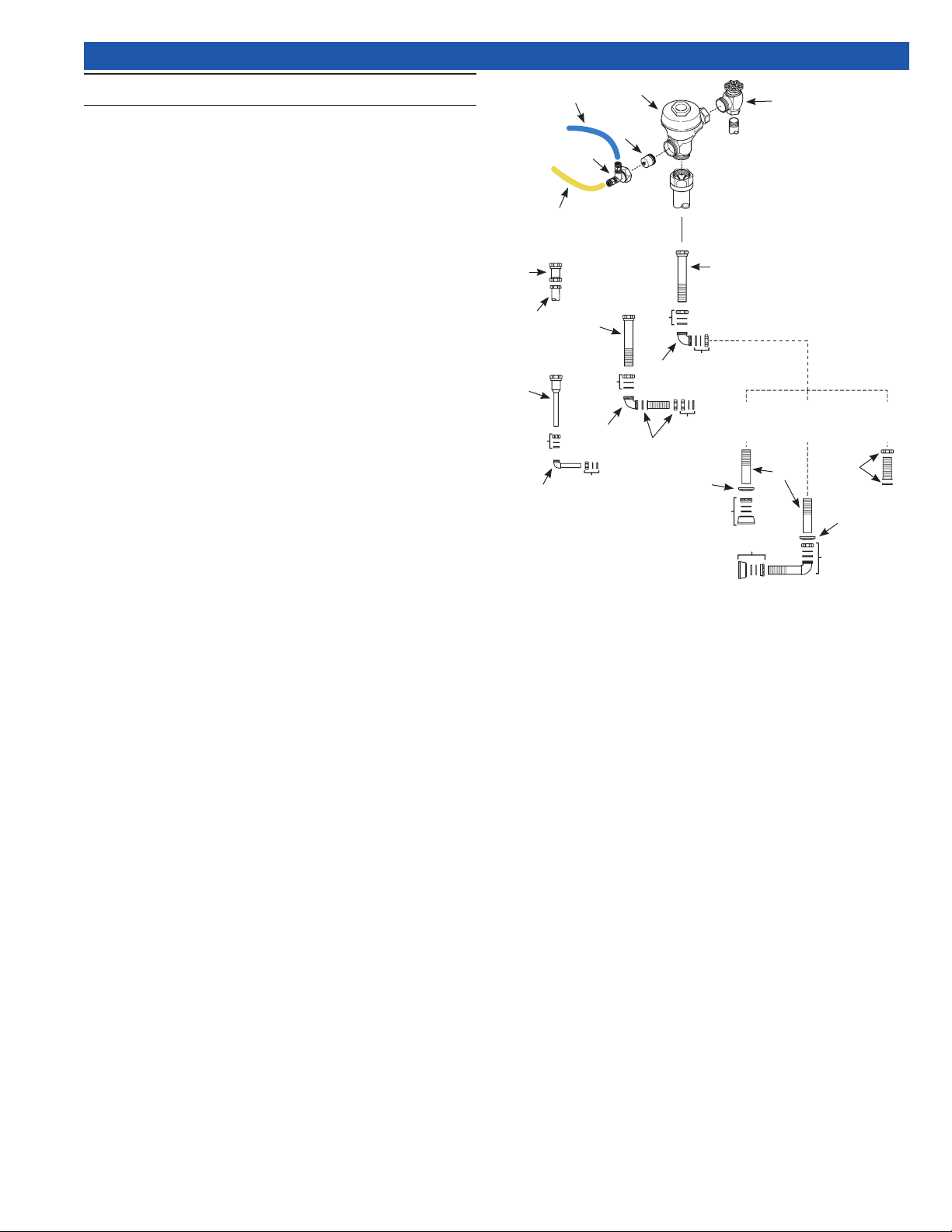
PARTS LIST
Item Part Description
No. No.
1 † Valve Assembly
2A HY-109-A Valve Actuator Housing
2B HY-83-A Actuator Cartridge
2C HY-145-X Blue 1/4” Connecting Tube
2C HY-146-X Yellow 1/4” Connecting Tube
2C
2A
2B
1
3
3 H-730-A Bak-Chek® Control Stop
4 V-500-A 1-1/2” (38 mm) Vacuum Breaker Assembly RB
5A F-22 1” (25 mm) Female Outlet RB
5B V-500-AA 3/4” (19 mm) x 10-1/2” (267 mm) Vacuum Breaker
5C V-500-AA 1-1/2” (38 mm) x 11-1/2” (292 mm) Vacuum Breaker
1-1/2” (38 mm) x 7-1/2” (191 mm) Vacuum Breaker
1-1/2” (38 mm) x 6” (152 mm) Vacuum Breaker
1-1/2” (38 mm) x 22” (559 mm) Vacuum Breaker
6 F-2-AW 3/4” (19 mm) Slip Joint Coupling RB
7 F-15-A ELL with 3/4” (19 mm) Tail RB (Model 995)
8 F-2-A 1-1/2” (38 mm) Slip Joint Coupling
9 F-21 1-1/2” (38 mm) Double Slip Elbow
10 F-2-A 1-1/2” (38 mm) Coupling with S-21 Gasket
11 F-110 1-1/4” (32 mm) Outlet Tube
12 F-2-AU 1-1/4” (32 mm) Slip Joint Coupling RB
13 F-2-AA 1-1/2” (38 mm) Slip Joint Coupling (Set of Two)
14 F-102 1-1/2” (38 mm) Outlet Tube CP
15 F-7 Flange
16 F-5-A 1-1/2” (38 mm) Spud Coupling Assembly CP
17 F-100 1-1/2” (38 mm) Outlet Tube RB
18 F-15-A 1-1/2” (38 mm) Elbow Assembly CP
†
Part number varies with valve model variation; consult factory.
Assembly RB
Assembly RB
Assembly RB
Assembly RB
Assembly RB
MODEL
950
4
5A
5B
2C
MODEL
995
6
7
5C
6
MODEL
8
9
990
10
11
13
5C
13
9
12
MODEL
940
15
16
MODEL
14
953
15
10
MODEL
952
17
16
18
SLOAN VALVE COMPANY • 10500 SEYMOUR AVENUE • FRANKLIN PARK, IL 60131
Phone: 1-800-982-5839 or 1-847-671-4300 • Fax: 1-800-447-8329 or 1-847-671-4380 • www.sloan.com
Copyright © 2017 SLOAN VALVE COMPANY Rev. 5 (10/17) – 0816301
 Loading...