

Page 1
OPTIMA Plus®EBF-85 Faucet
SENSOR FAUCETS
Parts Guide
•BATTERY OPERATED FAUCETS
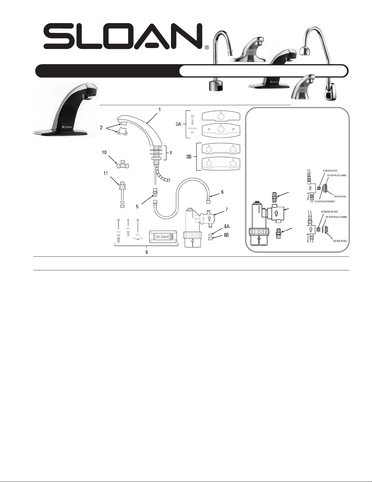
Parts List—EBF-85 Faucet
Item Code Par t Description
Number Number Number
1 3315016 EBF-10-A Faucet and Sensor Assembly (EBF-85)
0315115 EBF-179-A Fiber Optic Sensor Cable Assembly Only (replaces EBF-12-A)
TBA EBF-1009-A Fiber Optic Sensor Cable Assembly Only (replaces EBF-12-A, includes lens holder)
2 3365091 ETF-1021-A 0.5 gpm (1.9 Lpm) Spray Head with Key (female thread)
3365090 ETF-1022-A 2.2 gpm (8.3 Lpm) Aerator Spray Head with Key (female thread)
0305612 ETF-237 2.2 gpm (8.3 Lpm) Laminar Flow Spray Head (female thread)
0305927 ETF-435 Replacement Key ONLY for ETF-1021-A 0.5 gpm (1.9 Lpm) Spray Head and ETF-1022-A 2.2 gpm (8.3 Lpm) Aerator Spray Head
(NOT required for ETF-237 2.2 gpm/8.3 Lpm Laminar Flow Spray Head)
3A 3365466 ETF-295-A 4” (102 mm) Centerset Trim Plate Kit for Faucet (Faucet Only) includes two (2) Nuts, two (2) Hex Screws, two (2) Flat Washers,
Single Hole Cover Plate, and CP Base Plate
3B 3365467 ETF-299-A 4” (102 mm) Centerset Trim Plate Kit for Faucet with Optional Mixing Valve includes two (2) Nuts, two (2) Hex Screws, two (2) Flat
Washers, Dual Hole Cover Plate, and CP Base Plate
4 0305626 ETF-290-A Faucet Mounting Kit includes Rubber Gasket, Mounting Washer, Mounting Nut, and ETF-297 Compression Fitting Connector
5 0305736 ETF-297 1/4” to 3/8” Compression Fitting Connector
6 0305891 MIX-19 20” (508 mm) Flex Hose
7 3315011 EBF-11-A Solenoid Valve Module Assembly includes Solenoid Enclosure, Solenoid Body, and Filter Cap
8A 0305510 ETF-208 3/8” (10 mm) Ferrule
8B 0305511 ETF-209 3/8” (10 mm) Compression Nut
9 3315014 EBF-25-A Mounting Bracket Kit includes Base Plate, Wall Bracket Base, Wall Bracket, Mounting Screw, Self-tapping Screw, two (2) Wood
Screws plus Washers and Plastic Anchors, two (2) Screws plus Washers and Toggle Nuts, two (2) Screws plus Washers and
Hollow Wall Anchors
10 0305728 ETF-259 3/8” Tee Compression Fitting
11 3365001 ETF-470-A Back Check
12 0315004 EBF-17 3/8” to 1/4” Compression Fitting Connector
— 3315009 EBF-1001-A Solenoid Filter Replacement Kit for old solenoid includes Filter Screen Assembly and O-ring
— 3315028 EBF-1004-A Solenoid Filter Replacement Kit for current solenoid includes Filter Screen Assembly and O-ring
— 3315051 EBF-1005-A Filter Cap Assembly for old solenoid includes metal Filter Cover and O-ring
Solenoid Valve Changes
The current solenoid (in production since May 1998; part 7
shown on the left) has MALE inlet and outlet connections.
The current style filter plug has a metal filter cap that can
be removed with a 5/8” wrench.
The older solenoid valve (shown below) can be identified
by FEMALE inlet and outlet connections. These require
EBF-17 compression fittings (part 12 shown below).
This older style solenoid has either a plastic or a
replacement brass filter cap. Remove the older brass filter
cap with a 7/16” or 1/2” hex
wrench. Replace the old style filter
cap with an EBF-1005-A Filter Cap
Replacement Kit (brass cap).
12
old
solenoid
12
current
solenoid
The information contained in this document is subject to change without notice.
SLOAN VALVE COMPANY • 10500 SEYMOUR AVENUE • FRANKLIN PARK, IL 60131
Phone: 1-800-9-VALVE-9 or 1-847-671-4300 • Fax: 1-800-447-8329 or 1-847-671-4380 • http://www.sloanvalve.com
Copyright © 2003 Sloan Valve Company Printed in the U.S.A. Made in the U.S.A. OPTIMA FAU M.G. — Rev. 0a (05/03) Code No 0816518
old filter plug
current filter plug
Page 2
Troubleshooting Guide for EBF-85 Faucets
SENSOR FAUCETS
PP aa rr tt ss
Guide •BATTERY OPERATED FAUCETS
1. PROBLEM: Module emits audible “BEEPs” when activated.
CAUSE: Battery power is nearly exhausted.
SOLUTION: To ensure proper operation, insert four (4) new C-size
Alkaline batteries. Check that the orientation of each
battery matches the positive (+) and negative (–)
symbols shown in the bottom of the Battery
Compartment. Reattach Battery Compartment to Control
Module.
2. PROBLEM: Sensor is activated but faucet does not deliver water.
INDICATOR: Module DOES NOT produce audible “BEEPs”.
CAUSE: Battery power is fully exhausted.
SOLUTION: To ensure proper operation, insert four (4) new C-size
Alkaline batteries. Check that the orientation of each
battery matches the positive (+) and negative (–)
symbols shown in the bottom of the Battery
Compartment. Reattach Battery Compartment to Control
Module.
CAUSE: Batteries are not installed properly.
SOLUTION: Check that the orientation of the batteries match the
positive (+) and negative (–) symbols shown in the
bottom of the battery compartment. Reattach the Battery
Compartment to the Control Module.
CAUSE: Solenoid Valve Module is defective.
SOLUTION: Replace EBF-11-A Solenoid Valve Module.
INDICATOR: Module produces audible “BEEPs” when batteries are installed and
after 30-second calibration procedure, but NOT when a target is
placed in the detection zone of the Sensor.
CAUSE: Fiber Optic Cable is not connected correctly to Solenoid
Valve Module or was not connected when batteries were
installed.
SOLUTION: Reconnect Fiber Optic Cable to Solenoid Valve Module.
Open Battery Compartment to reset electrical system.
Check that the orientation of each battery matches the
positive (+) and negative (–) symbols shown in the
bottom of the battery compartment. Reattach the Battery
Compartment to the Control Module.
CAUSE: Fiber Optic Cable is defective.
SOLUTION: Replace EBF-179-A Sensor Cable, EBF-1009-A Sensor
Cable, or EBF-10-A Faucet/Sensor Assembly.
CAUSE: Solenoid Valve Module is defective.
SOLUTION: Replace EBF-11-A Solenoid Valve Module.
INDICATOR: Module produces audible “BEEPs” when a target is placed in the
detection zone of the Sensor and Solenoid Valve produces an
audible “CLICK”, but NO water flows.
CAUSE: Water supply to faucet is not open.
SOLUTION: Open supply stop(s).
CAUSE: Back Check is installed backwards.
SOLUTION: Reinstall Back Check(s).
CAUSE: Solenoid Filter is clogged.
SOLUTION: Remove, clean, and reinsert. Replace with EBF-1001-A
or EBF-1004-A Solenoid Filter Kit if necessary.
CAUSE: Aerator or Spray head is clogged.
SOLUTION: Remove, clean, and reinsert.
INDICATOR: Module produces audible “BEEPs” when a target is placed in the
detection zone of the Sensor, but Solenoid Valve does NOT produce
an audible “CLICK” and NO water flows.
CAUSE: Solenoid Valve Module is defective.
SOLUTION: Replace EBF-11-A Solenoid Valve Module.
3. PROBLEM: Faucet delivers only a slow flow or dribble when
Sensor is activated.
CAUSE: Water supply valve is partially closed.
SOLUTION: Open the Supply Stop(s) completely.
CAUSE: Solenoid Filter is clogged.
SOLUTION: Remove, clean, and reinsert. Replace with EBF-1001-A
or EBF-1004-A Solenoid Filter if necessary.
CAUSE: Aerator or Spray head is clogged.
SOLUTION: Remove, clean, and reinsert.
4. PROBLEM: Faucet does not stop delivering water or continues to
drip after user is no longer detected (automatic shutoff fails even when batteries are removed).
CAUSE: Solenoid Valve has been connected backwards.
SOLUTION: Disassemble Solenoid Valve compression fittings at the
inlet and outlet positions. Water should flow from inlet
through the Solenoid Valve to outlet according to the
direction shown by the arrow on the side of the Solenoid
Valve. Reconnect the fittings in the correct orientation.
CAUSE: Solenoid Valve seat is dirty.
SOLUTION: Remove, clean, and reinsert Solenoid Filter. Activate
faucet several times to flush out dirt.
CAUSE: Solenoid Valve is dirty.
SOLUTION: Backflush by reversing water flow (opposite to the
direction shown by the arrow on the side of the Solenoid
Valve) through the Solenoid Valve. Reconnect the
compression fittings in the correct orientation.
Activate faucet.
CAUSE: Solenoid Valve Module is defective.
SOLUTION: Replace EBF-11-A Solenoid Valve Module.
5. PROBLEM: The water temperature is too hot or too cold on a
faucet connected to hot and cold supply lines
with two Back Checks.
CAUSE: Supply Stops are not adjusted properly.
SOLUTION: Adjust Supply Stops.
CAUSE: One Back Check is installed backwards.
SOLUTION: Reinstall Back Check.
NOTE: For some systems, a Thermostatic Mixing Valve may be required.
NOTE: BEEP sounds are emitted from the Solenoid Valve Module (not from the Spout of the
Faucet). For the first ten (10) minutes of operation (or after battery replacement), the unit
BEEPs every time the faucet is activated to indicate that range limits are set. To conserve
battery power, the unit will not BEEP again until it indicates low battery power.
Calibration Procedure: When the battery compartment is assembled to the valve module with
active batteries, the faucet initiates a self-calibration mode and uses BEEPs to indicate the
status of this mode. To prevent improper calibration, ensure that the Spout is centered
properly and that no targets are in the detection range of the sensor when the batteries are
connected. An initial series of BEEPs indicates that power is being supplied from the batteries
to the faucet. For the next thirty (30) seconds, the sensor determines the most suitable range
setting for its environment. Water will not flow from the faucet during this automatic range
calibration. After the range is calibrated, a second series of BEEPs indicates that the faucet is
ready for use. Under normal operation, this faucet adapts its range to changes in the
environment.
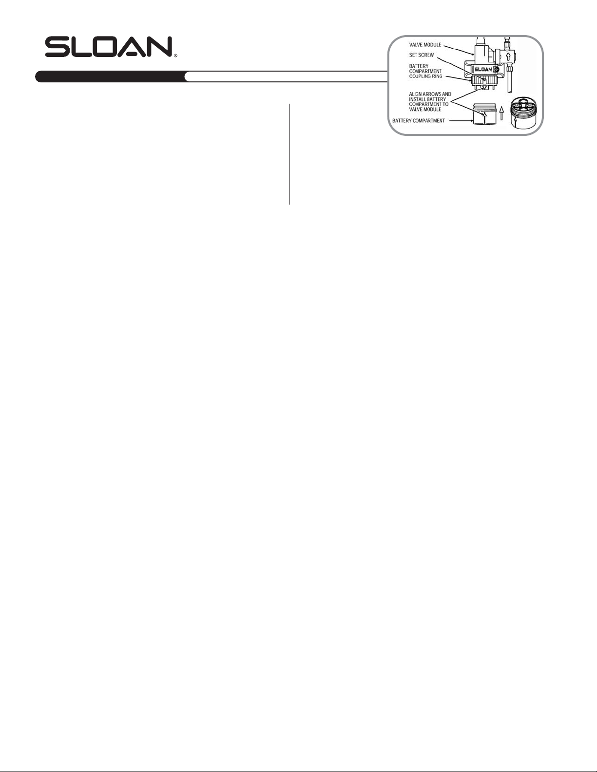
Battery Replacement Procedure:
Loosen security set screw on the
Coupling Ring with a 0.05” hex or
allen wrench. Unscrew Battery Compartment Coupling Ring. Remove Batter y Compartment. To
ensure proper operation, remove old batteries and insert four (4) new C-size Alkaline batteries.
Check that the orientation of each battery matches the positive (+) and negative (–) symbols
shown in the bottom of the Battery Compartment. Reattach the Batter y Compartment to the
Control Module by aligning the arrow on the Battery Compartment with the arrow on the solid
tab of the Solenoid Valve Module. Secure by tightening Battery Compartment Coupling Ring.
To deter unauthorized removal of batteries, use a 0.05” hex or allen wrench to tighten the
Security Set Screw on the Coupling Ring.
If further assistance is required, please contact the Sloan Valve Company Installation Engineering Department at
1-888-SLOAN-14
(1-888-756-2614).
2
Page 3
Mounting Kit and Faucet Shank
The new mounting kit (in production since June
1999; part 4 shown on the left) includes parts for
installation on both thin and thick surfaces, an
ETF-591 male compression fitting, and an antirotation screw for installation on sheet metal
surfaces less than 0.41” (10 mm) thick. For
surfaces between 0.41” (10 mm) and 1.00” (25
mm) thick, use the mounting spacer and
mounting stud hardware*. The faucet sensor
cable is threaded through a groove on the side of
the shank.
The older mounting kit (in production in early
1999; part 9 shown below) can be identified by a
copper supply tube attached to the faucet shank,
requires an ETF-547 compression fitting, and
threads the faucet sensor cable through the
9
10
New Base Gasket
The new base gasket (in production
since October 1999) is shown at left.
An older base gasket design did not
have the u-shaped drainage hole.
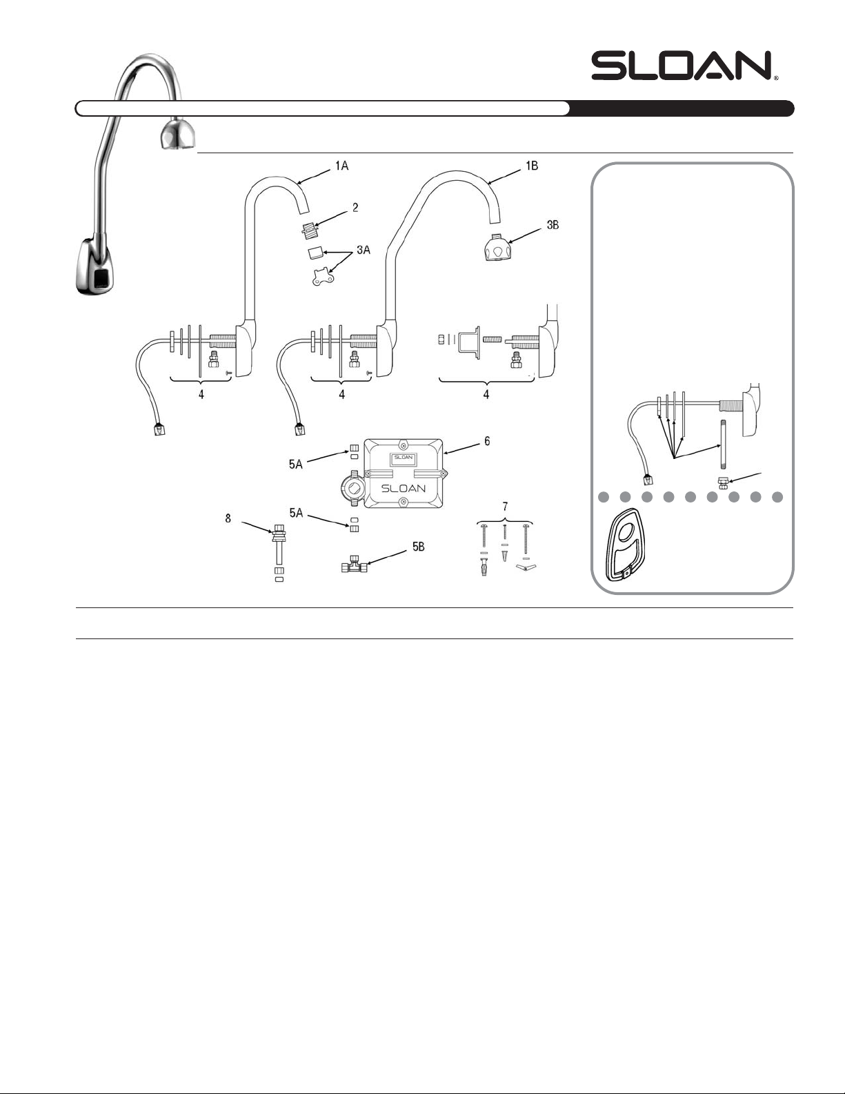
OPTIMA Plus®EBF-550 Faucet
Parts List—EBF-550 Faucet
Item Code Par t Description
Number Number Number
1A 0315061 EBF-94-A Faucet and Sensor Assembly with Standard Gooseneck Spout (EBF-550)
1B 0315062 EBF-95-A Faucet and Sensor Assembly with Surgical Bend Gooseneck Spout (EBF-550-S)
2 0305784 ETF-178 Adapter for Spray Heads (not required for AC-55-A Shower Spray Head)
3A 3365091 ETF-1021-A 0.5 gpm (1.9 Lpm) Spray Head with Key (female thread)
3365090 ETF-1022-A 2.2 gpm (8.3 Lpm) Aerator Spray Head with Key (female thread)
0305612 ETF-237 2.2 gpm (8.3 Lpm) Laminar Flow Spray Head (female thread)
0305927 ETF-435 Replacement Key ONLY for ETF-1021-A 0.5 gpm (1.9 Lpm) Spray Head and ETF-1022-A 2.2 gpm (8.3 Lpm) Aerator Spray Head
(NOT required for ETF-237 2.2 gpm/8.3 Lpm Laminar Flow Spray Head)
3B 0328134 AC-55-A Shower Spray Head Assembly, 2.2 gpm (8.3 Lpm)
4 0315060 EBF-110-A Faucet Mounting Kit includes Base Gasket, large Flat Washer, large Lockwasher, large Nut, Mounting Spacer, Mounting Stud, small
Flat Washer, small Lockwasher, small Nut, Anti-Rotation Screw, and ETF-591 Compression Fitting Connector (male)
0365152 ETF-591 1/8” NPT Pipe to 3/8” Tube Male Compression Fitting Connector
5A 3315029 EBF-113-A Single Solenoid Supply Kit includes two (2) Compression Nuts, two (2) Compression Sleeves, and Screwdriver
5B 0305728 ETF-259 3/8” Tee Compression Fitting
6 0315104 EBF-60-A Control Module Assembly includes Base Enclosure, Cover Enclosure, two (2) Gaskets, Solenoid Body, Solenoid Enclosure, Solenoid
Filter Cap, and Battery Stop
7 3315018 EBF-79-A Mounting Hardware Kit for Control Module Assembly includes four (4) Anchor Nuts, four (4) Toggle Nuts, four (4) Mounting Screws
for Base Plate, four (4) Flat Washers, four (4) Anchors, and four (4) Metal Screws
8 3365001 ETF-470-A Back Check
9 n/a EBF-110-A Old Faucet Mounting Kit includes 3/8” Water Supply Tube, Base Gasket, large Flat Washer, large Lockwasher, large Nut, and ETF-547
Compression Fitting Connector (order items 4 and 10 as replacement parts)
10 0365058 ETF-547 1/8” NPT Pipe to 3/8” Tube Female Compression Fitting Connector
— 0315048 EBF-107-A Sensor Housing and Cable Assembly Replacement Kit
— 0315035 EBF-62-A Solenoid Replacement Kit includes Solenoid Body, Solenoid Enclosure, and Solenoid Filter Cap
— 3315028 EBF-1004-A Solenoid Filter Replacement Kit includes Filter Screen Assembly and O-ring
— 3315073 EBF-1006-A Repair Kit for EBF-60 Control Module Assembly includes EBF-61-A Battery Holder Assembly and EBF-159 Battery Gasket
— 0315034 EBF-50-A Control Module Replacement Gaskets (2 Required)
SENSOR FAUCETS
Parts Guide
BATTERY OPERATED FAUCETS•
* To mount faucet on a surface
between 0.41” (10 mm) and
1.00” (25 mm) thick, use the
hardware shown below.
3
Page 4
SENSOR FAUCETS
Parts Guide •BATTERY OPERATED FAUCETS
OPTIMA Plus®EBF-615 and EBF-650 Faucets
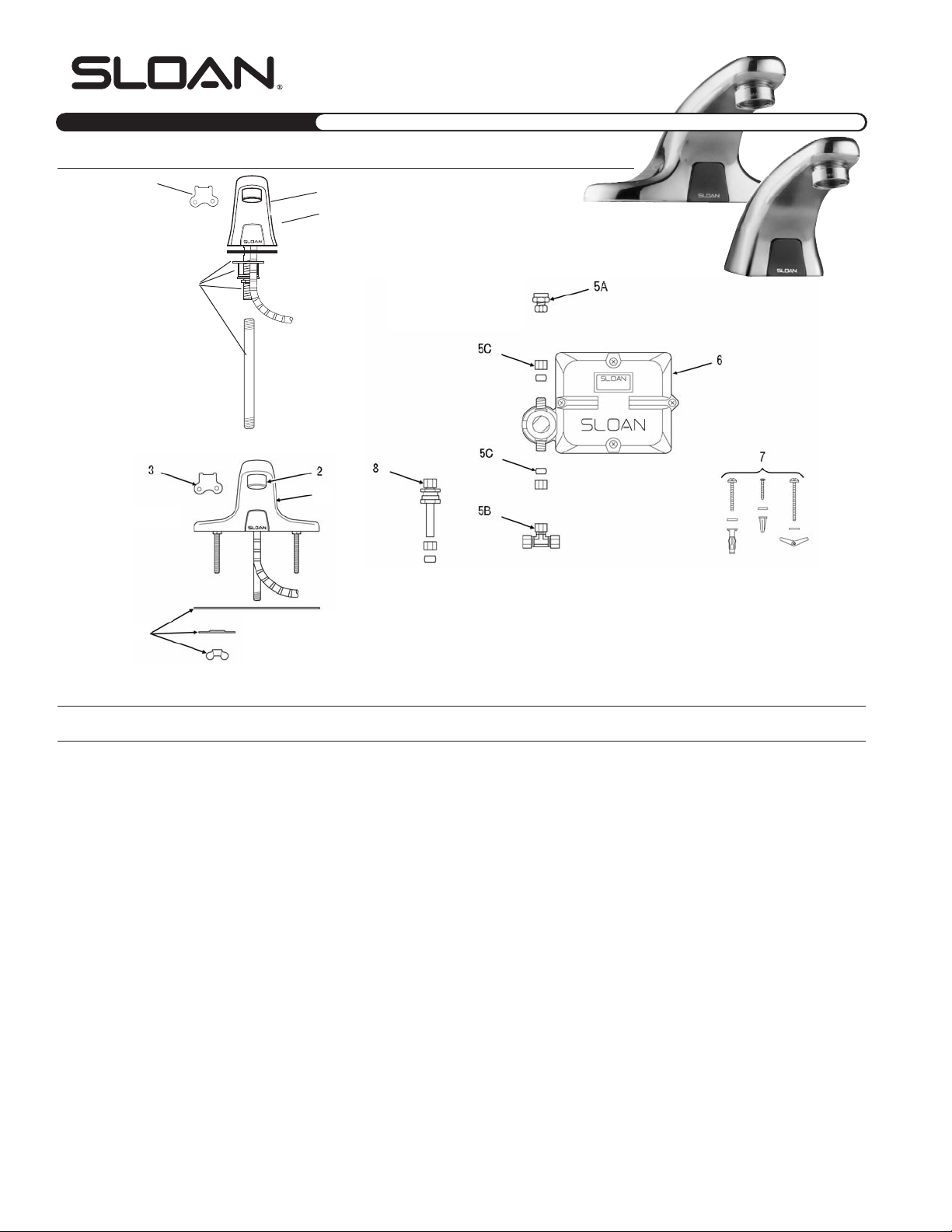
Parts List—EBF-615 and EBF-650 Faucets
Item Code Par t Description
Number Number Number
1A 0315083 EBF-120-A Pedestal Faucet Spout and Sensor Assembly (EBF-615)
1B 0315054 EBF-81-A Faucet Spout and Sensor Assembly (EBF-650)
2 3365092 ETF-1023-A 0.5 gpm (1.9 Lpm) Spray Head with Key (male thread)
3365093 ETF-1024-A 2.2 gpm (8.3 Lpm) Aerator Spray Head with Key (male thread)
0305607 F-175-L 2.2 gpm (8.3 Lpm) Laminar Flow Spray Head (male thread)
3 0305927 ETF-435 Replacement Key Only for ETF-1023-A 0.5 gpm (1.9 Lpm) Spray Head and ETF-1024-A 2.2 gpm (8.3 Lpm) Aerator Spray Head
(NOT required for F-175-L 2.2 gpm/8.3 Lpm Laminar Flow Spray Head)
4A 0315085 EBF-123-A Faucet Mounting Kit for EBF-615 includes Spacer, Base Gasket, 1/4” NPSM Hex Nut, Washer, 9/16” Lockwasher, ETF-547
Compression Fitting Connector, and 3/8” RB Water Supply Tube
4B 3365088 ETF-546-A Faucet Mounting Kit for EBF-650 includes Base Gasket, two (2) Slotted Mounting Washers, two (2) Wing Nuts, and ETF-547
Compression Fitting Connector
5A 0365058 ETF-547 1/8” NPT Pipe to 3/8” Tube Compression Fitting Connector (female)
5B 0305728 ETF-259 3/8” Tee Compression Fitting
5C 3315029 EBF-113-A Single Solenoid Supply Kit includes two (2) Compression Nuts, two (2) Compression Sleeves, and Screwdriver
6 0315104 EBF-60-A Control Module Assembly includes Base Enclosure, Cover Enclosure, two (2) Gaskets, Solenoid Body, Solenoid Enclosure, Solenoid
Filter Cap, and Battery Stop
7 3315018 EBF-79-A Mounting Hardware Kit for Control Module Assembly includes four (4) Anchor Nuts, four (4) Toggle Nuts, four (4) Mounting Screws
for Base Plate, four (4) Flat Washers, four (4) Anchors, and four (4) Metal Screws
8 3365001 ETF-470-A Back Check
— 0315040 EBF-80-A Sensor Replacement Kit includes Cable Assembly, Retainer for PC Board Assembly, and Housing for Sensor Window
— 0315035 EBF-62-A Solenoid Replacement Kit includes Solenoid Body, Solenoid Enclosure, and Solenoid Filter Cap
— 3315028 EBF-1004-A Solenoid Filter Replacement Kit includes Filter Screen Assembly and O-ring
— 3315073 EBF-1006-A Repair Kit for EBF-60 Control Module Assembly includes EBF-61-A Battery Holder Assembly and EBF-159 Battery Gasket
— 0315034 EBF-50 Control Module Replacement Gasket (two required)
— 3315074 EBF-1007-A Faucet Cable Assembly Repair Kit for EBF-650 includes Sensor Window Housing Assembly and Bracket for Sensor Window
EBF-650
1B
4B
EBF-615
2
1A
3
4A
4
Page 5
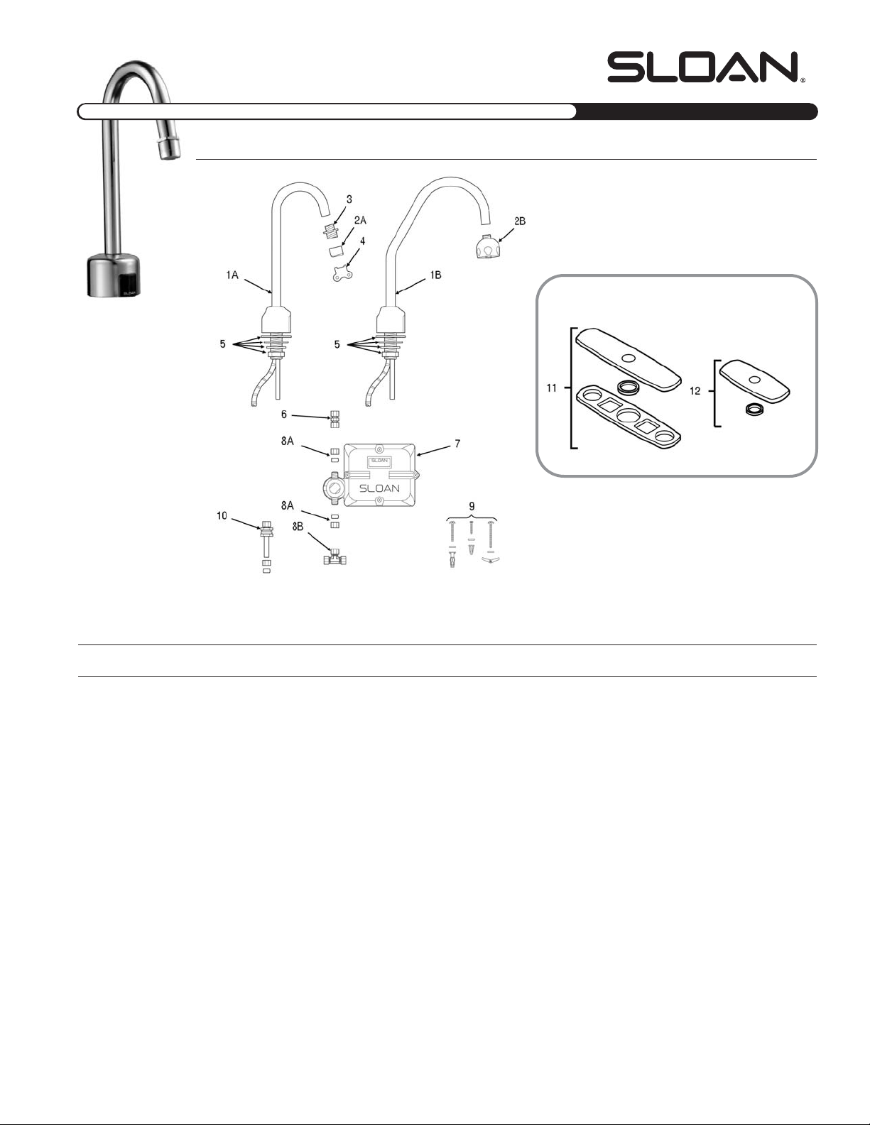
OPTIMA Plus®EBF-750 Faucet
Parts List—EBF-750 Faucet
Item Code Par t Description
Number Number Number
1A 0315076 EBF-140-A Faucet/Sensor Assembly with Standard Gooseneck Spout (EBF-750)
1B 0315077 EBF-141-A Faucet/Sensor Assembly with Surgical Bend Gooseneck Spout (EBF-750-S)
2A 3365091 ETF-1021-A 0.5 gpm (1.9 Lpm) Spray Head with Key (female thread)
3365090 ETF-1022-A 2.2 gpm (8.3 Lpm) Aerator Spray Head with Key (female thread)
0305612 ETF-237 2.2 gpm (8.3 Lpm) Laminar Flow Spray Head (female thread)
2B 0328134 AC-55-A Shower Spray Head Assembly, 2.2 gpm (8.3 Lpm)
3 0305784 ETF-178 Adapter for Spray Heads (not required for AC-55-A Shower Spray Head)
4 0305927 ETF-435 Replacement Key Only for ETF-1021-A 0.5 gpm (1.9 Lpm) Spray Head and ETF-1022-A 2.2 gpm (8.3 Lpm) Aerator Spray Head
(NOT required for ETF-237 2.2 gpm/8.3 Lpm Laminar Flow Spray Head)
5 0365110 ETF-503-A Spout Mounting Kit includes Rubber Gasket, Flat Washer, Lockwasher, Mounting Nut, and ETF-530 Union Compression Fitting
6 0365057 ETF-530 3/8” x 3/8” Union Compression Fitting (female)
7 0315104 EBF-60-A Control Module Assembly includes Base Enclosure, Cover Enclosure, two (2) Gaskets, Solenoid Body, Solenoid Enclosure, Solenoid
Filter Cap, and Battery Stop
8A 3315029 EBF-113-A Single Solenoid Supply Kit includes two (2) Compression Nuts, two (2) Compression Sleeves, and Screwdriver
8B 0305728 ETF-259 3/8” Tee Compression Fitting
9 3315018 EBF-79-A Mounting Hardware Kit for Control Module Assembly includes four (4) Anchor Nuts, four (4) Toggle Nuts, four (4) Mounting Screws
for Base Plate, four (4) Flat Washers, four (4) Anchors, and four (4) Metal Screws
10 3365001 ETF-470-A Back Check
11 3365601 ETF-431-A Optional 8” (203 mm) Centerset Trim Plate Kit includes Seal, two (2) Washer Fenders, two (2) Gaskets, two (2) Finger Nuts, Trim
Plate Spacer, and Single Hole Trim Plate Assembly
12 3365468 ETF-312-A Optional 4” (102 mm) Centerset Trim Plate Kit includes Trim Plate Spacer and Single Hole Trim Plate Assembly
— 0315057 EBF-138-A Sensor Replacement Kit includes Sensor Housing and Cable Assembly
— 0315035 EBF-62-A Solenoid Replacement Kit includes Solenoid Body, Solenoid Enclosure, and Solenoid Filter Cap
— 3315028 EBF-1004-A Solenoid Filter Replacement Kit includes Filter Screen Assembly and O-ring
— 3315073 EBF-1006-A Repair Kit includes for EBF-60 Control Module Assembly includes EBF-61-A Battery Holder Assembly and EBF-159 Battery Gasket
— 0315034 EBF-50 Control Module Replacement Gaskets (two Required)
SENSOR FAUCETS
Parts Guide
BATTERY OPERATED FAUCETS•
Optional Trim Plate Kits
5
Page 6
1. PROBLEM: Sensor troubleshooting LED does not
function (red indicator light does not flash
during set-up procedure).
CAUSE: No battery power is being supplied to Sensor.
SOLUTION: Ensure that the batteries are installed properly. Check
that the orientation of each battery matches the
positive (+) and negative (–) symbols shown on the
bottom of the battery compartment. Reinsert the Battery
Compartment into the Control Module.
CAUSE: Insufficient battery power is being supplied to sensor.
SOLUTION: One (or more) of the batteries is “dead”. To ensure
proper operation, insert four (4) new C-size Alkaline
batteries. Check that the orientation of each battery
matches the positive (+) and negative (–) symbols
shown on the bottom of the Battery Compartment.
Reinsert the Battery Compartment into the Control
Module.
CAUSE: Sensor Cable is not properly inserted.
SOLUTION: Disconnect and reconnect Sensor Cable to the Control
Module.
CAUSE: Sensor range is set at minimum distance.
SOLUTION: Increase Sensor range. Use a small phillips screwdriver
to turn the potentiometer screw (white screw in a
blue base) clockwise.
CAUSE: Control Module assembly is defective.
SOLUTION: Replace EBF-60-A Control Module assembly
2. PROBLEM: Faucet does not deliver any water when Sensor is
activated.
INDICATOR: Solenoid valve produces audible “CLICK”.
CAUSE: Water supply valve is closed.
SOLUTION: Open the Supply Stop.
INDICATOR: Solenoid valve DOES NOT produce an audible “CLICK”.
CAUSE: Solenoid lead is not properly connected to the Control
Module.
SOLUTION: Disconnect and reconnect Solenoid lead to the Control
Module.
CAUSE: Batteries are not installed properly.
SOLUTION: Check that the orientation of each battery matches the
positive (+) and negative (–) symbols shown on the
bottom of the battery compartment. Reinsert the Battery
Compartment into the Control Module. The
troubleshooting LED should flash RED when a user is
detected.
3. PROBLEM: Faucet delivers only a slow flow or dribble when
Sensor is activated.
CAUSE: Water supply valve is partially closed.
SOLUTION: Completely open the Supply Stop.
CAUSE: Solenoid Filter is clogged.
SOLUTION: Remove, clean, and reinsert. Replace EBF-1004-A
Solenoid Filter Kit if necessary.
CAUSE: Aerator or Spray head is clogged.
SOLUTION: Remove, clean, and reinsert.
4. PROBLEM: Faucet does not stop delivering water or continues to
drip after user is no longer detected (automatic shut
off fails even when batteries are removed).
CAUSE: Solenoid Valve has been connected backwards.
SOLUTION: Disassemble Solenoid Valve Compression Fittings at both
the inlet and outlet positions. The water should flow from
inlet through the Solenoid Valve to the outlet according to
the direction of the arrow shown on the side of the
Solenoid Valve. Reconnect the Compression Fittings in
the correct orientation.
CAUSE: Solenoid Valve is dirty.
SOLUTION: Backflush by reversing water flow (opposite to the
direction shown by the arrow on the side of the Solenoid
Valve) through the Solenoid Valve. Reconnect the
compression fittings in the correct orientation.
Activate faucet.
CAUSE: Solenoid Valve Module is defective.
SOLUTION: Replace EBF-62-A Solenoid Valve Module.
5. PROBLEM: The water temperature is too hot or too cold on a
faucet connected to hot and cold supply lines
with two Back Checks.
CAUSE: Supply Stops are not adjusted properly.
SOLUTION: Adjust Supply Stops.
CAUSE: One Back Check is installed backwards.
SOLUTION: Reinstall Back Check.
NOTE: For some systems, a Thermostatic Mixing Valve may be required.
SENSOR FAUCETS
Parts Guide •BATTERY OPERATED FAUCETS
Troubleshooting Guide for EBF-550, EBF-615, EBF-650, and EBF-750 Faucets
NOTE: Range Potentiometer adjustment screw rotates only 3/4 of a turn (270°).
Do not overrotate!
Care and Cleaning Instructions
DO NOT USE abrasive or chemical cleaners to clean Faucets that may dull the
luster and attack the chrome or special decorative finishes. Use ONLY soap and
water, then wipe dry with a clean towel or cloth.
When cleaning the bathroom tile, protect the Faucet from any splattering of
cleaner. Acids and cleaning fluids can discolor or remove chrome plating.
If further assistance is required, please contact the Sloan Valve Company Installation Engineering Department at
1-888-SLOAN-14 (1-888-756-2614).
The information contained in this document is subject to change without notice.
SLOAN VALVE COMPANY • 10500 SEYMOUR AVENUE • FRANKLIN PARK, IL 60131
Phone: 1-800-9-VALVE-9 or 1-847-671-4300 • Fax: 1-800-447-8329 or 1-847-671-4380 • http://www.sloanvalve.com
Copyright © 2003 Sloan Valve Company Printed in the U.S.A. Made in the U.S.A. OPTIMA FAU M.G. — Rev. 0a (05/03) Code No 0816518
LIMITED WARRANTY
Sloan Valve Company warrants its Faucet Products to be made of first class materials, free from defects of material or workmanship under normal use and to perform the service for which they are intended in a thoroughly
reliable and efficient manner when properly installed and serviced, for a period of three years (one year for special finishes) from date of purchase. During this period, Sloan Valve Company will, at its option, repair or replace
any part or par ts which prove to be thus defective if returned to Sloan Valve Company, at customer’s cost, and this shall be the sole remedy available under this warranty. No claims will be allowed for labor, transportation
or other incidental costs. This warranty extends only to persons or organizations who purchase Sloan Valve Company’s products directly from Sloan Valve Company for purpose of resale.
THERE ARE NO WARRANTIES WHICH EXTEND BEYOND THE DESCRIPTION ON THE FACE HEREOF. IN NO EVENT IS SLOAN VALVE COMPANY RESPONSIBLE FOR ANY CONSEQUENTIAL DAMAGES OF ANY MEASURE WHATSOEVER.
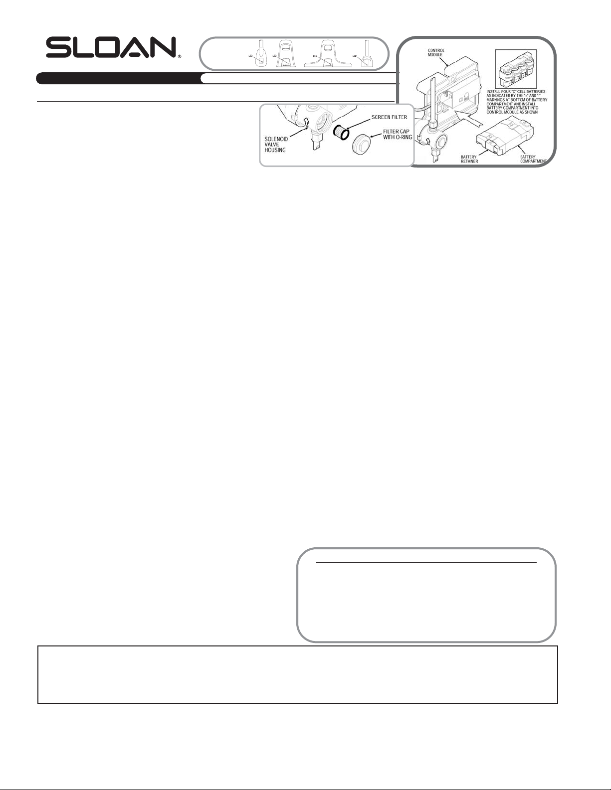
SENSOR
INDICATOR
LIGHTS
BATTERY REPLACEMENT
SOLENOID SCREEN FILTER AND CAP
 Loading...