

Page 1
OPTIMA®Flushometers
LIMITED WARRANTY
Sloan Valve Company warrants its Flushometer Products to be made of first class
materials, free from defects of material or workmanship under normal use and to
perform the service for which they are intended in a thoroughly reliable and efficient
manner when properly installed and serviced, for a period of three years (one year
for special finishes) from date of purchase. During this period, Sloan Valve
Company will, at its option, repair or replace any part or par ts which prove to be thus
defective if returned to Sloan Valve Company, at customer’s cost, and this shall be
the sole remedy available under this warranty. No claims will be allowed for labor,
transportation or other incidental costs. This warranty extends only to persons or
organizations who purchase Sloan Valve Company’s products directly from Sloan
Valve Company for purpose of resale.
THERE ARE NO WARRANTIES WHICH EXTEND BEYOND THE DESCRIPTION ON
THE FACE HEREOF. IN NO EVENT IS SLOAN VALVE COMPANY RESPONSIBLE FOR
ANY CONSEQUENTIAL DAMAGES OF ANY MEASURE WHATSOEVER.
Maintenance Guide
• SENSOR OPERATED VALVES
The information contained in this document is subject to change without notice.
OPTIMA ESS M.G. – Rev. 0a (05/03) Code No. 0816510
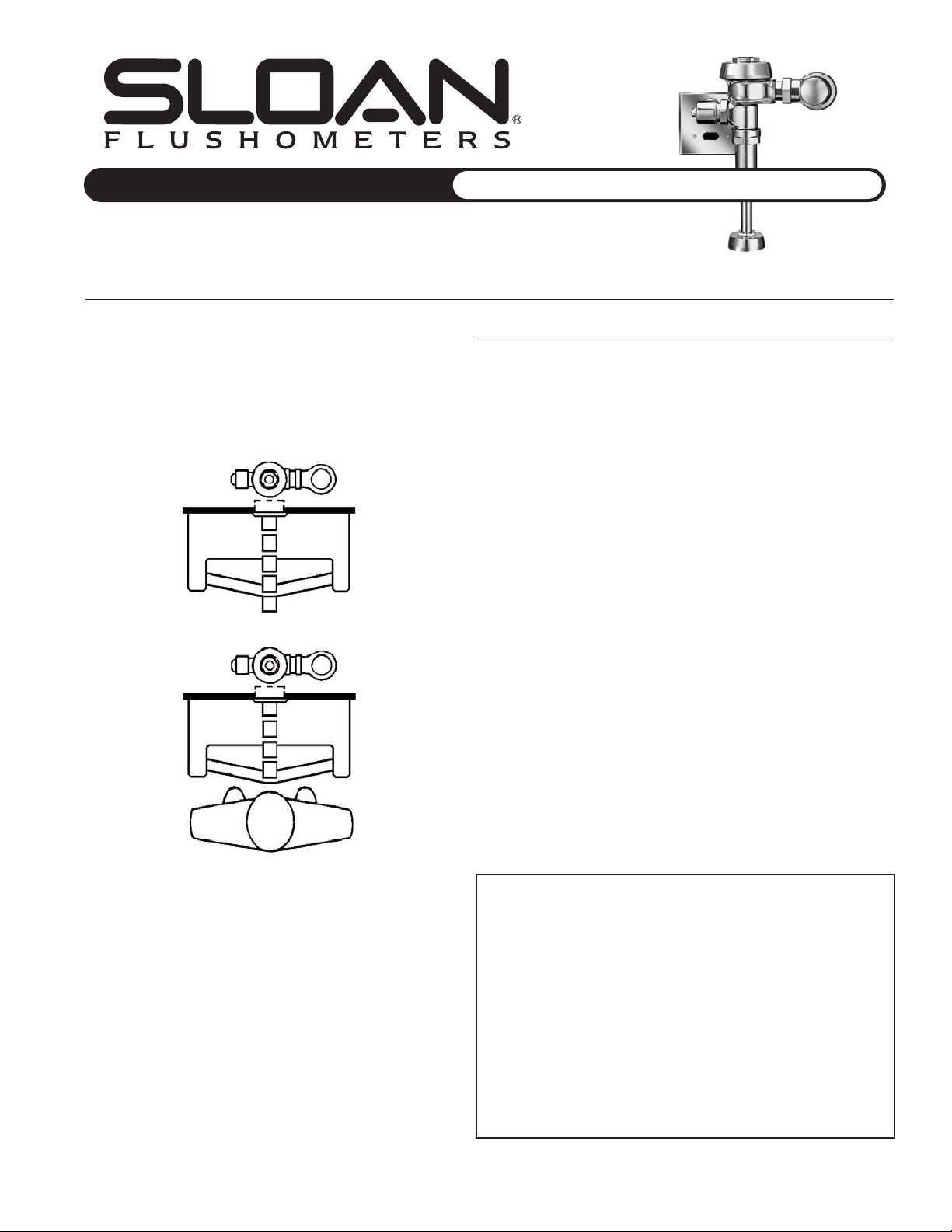
The Sloan OPTIMA automatic electronic Flushometer relies on an
infrared sensor to detect a user and activate a flushing cycle. No
physical contact with the Flushometer surface is necessary, assuring
sanitary protection. OPTIMA Flushometers are ADA-compliant
devices and are available in both Royal
®
and Regal®Flushometer
models. These hardwire Flushometers require the use of 24 VAC
Stepdown Transformers.
OPTIMA Components:
EL-1500 Series Sensor
• Self-adaptive Sensor
• Flashing Red Light Indicator
• Replaceable Sensor Window
• Two-wire connection system
Solenoid
• Non-Hold-Open Integral Solenoid Operator
Transformer
24 VAC Stepdown Transformer
• EL-154 for 120 VAC Electrical Supply (50/60 Hz)
• EL-342 for 220/240 VAC Electrical Supply (50/60 Hz)
Override Button
• Courtesy Flush
(available only on Water Closet installations)
Cover Plates
• Override Button Sensor Cover Plate
(Exposed and Concealed Water Closet installations)
• Solenoid Cover Plate
(Exposed Water Closet and Urinal installations)
• Urinal Sensor Cover Plate
(Concealed Urinal installations)
Wall Box Option
• Stainless Steel or Polished Brass Surface Finish
• Concealed installation
• Vandal Resistant
The Flushometer is triggered by means of a self-adaptive infrared
sensor. A flashing red indicator light identifies the presence of a
target. After a detected user moves out of the effective range of the
sensor, a signal is sent to the Flushometer Solenoid and, after
appropriate arming and/or flush delays, the flush cycle is initiated.
When a unit is used intermittently, the Sentinel Flush feature ensures
a cleansing cycle at least once in any 24-hour period.
NOTE: Sensor location and positioning is critical. Failure to properly position
the electrical box to the recommended plumbing rough-in dimensions will
result in improper installation and may impair product performance. All
tradesmen (plumbers, electricians, tile setters, etc.) involved in the
installation of this product must coordinate their work efforts to ensure
proper product installation. Improper installation may nullify the
manufacturer’s warranty.
Page 2
2
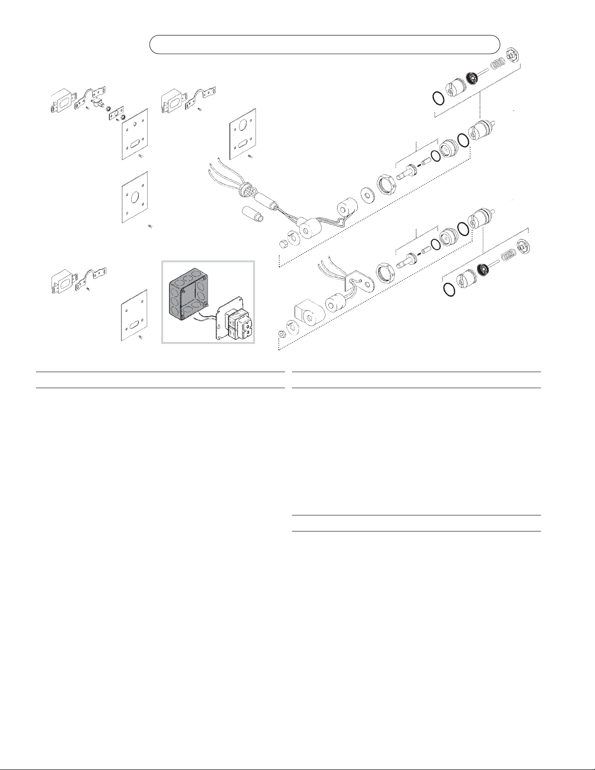
Solenoid/Sensor Parts and Assemblies List
Code Part Description
Number Number
1A 3305043 EL-128-A Actuator Cartridge Assembly Repair Kit
Includes Spring, EL-110 O-Ring, Plunger Guide, Solenoid Valve Seat,
Valve Piston Assembly, and DO-22 O-Ring.
1B 0305135 EL-110 O-Ring
2A 0305329 EL-124-2 CP 24 VAC Solenoid Assembly (exposed installation)
Includes A-6 CP Handle Coupling (0301082), EL-165-2 24 VAC Coil
(0305118), EL-101 CP Nut for Solenoid (0305125), EL-102-2 Face Plate
for 24 VAC Solenoid (0305127), EL-104 CP Adapter for Solenoid
(0305132), EL-162 CP Solenoid Housing (0305164), EL-163-A Solenoid
Shaft Assembly (0305165), EL-164 Solenoid Flux Plate (0305166), and
DO-22 O-Ring (0337086).
2B 0305331 EL-138-2 RB 24 VAC Solenoid Assembly (concealed installation)
Includes A-6 RB Handle Coupling (0301082PO), EL-165-2 24 VAC Coil
(0305118), EL-102-2 Face Plate for 24 VAC Solenoid (0305127), EL-104
CP Solenoid Adapter (0305132), EL-163-A Solenoid Shaft Assembly
(0305165), EL-166 Housing Nut for Solenoid (0305167),EL-137 Solenoid
Flux Plate (0305332), and EL-136 Solenoid Housing (0305336).
3A 0337086 DO-22 O-Ring
3B 0305132 EL-104 CP Adapter for Solenoid
3C 0305165 EL-163-A Solenoid Shaft Assembly
Includes Gasket, Plunger, Plunger Spring, and Solenoid Shaft.
4A 0301082 A-6 CP Handle Coupling (exposed installation)
4B 0301083 A-6 RB Handle Coupling (concealed installation)
5A 0305166 EL-164 Solenoid Flux Plate (exposed installation)
5B 0305332 EL-137 Solenoid Flux Plate (concealed installation)
6 0305118 EL-165-2 24 VAC Coil
7A 0305164 EL-162 CP Solenoid Housing (exposed installation)
7B 0305336 EL-136 CP Solenoid Housing (concealed installation)
8A 0305127 EL-102-2 Face Plate for 24 VAC Solenoid (exposed installation)
8B 0305333 EL-102-4 Face Plate for 24 VAC Solenoid (concealed installation)
9A 0305125 EL-101 CP Nut for Solenoid (exposed installation)
9B 0305167 EL-166 Housing Nut for Solenoid (concealed installation)
10A 0305145 EL-123-A CP Nipple Assembly (exposed installation)
10B 0305337 EL-226 CP Extension Nipple Adapter
NOTE: When the distance between Center Line of valve to finished wall
is greater than 3" (76 mm) use the EL-226 Extension Nipple Adapter.
These Adapters can be coupled as needed.
Code Part Description
Number Number
11 0305139 EL-176-A CP Flange Assembly (exposed installation)
12 0305152 EL-152 CP Screws (requires four screws per cover plate)
13 0305151 EL-151 CP Cover Plate for Sensor and Solenoid Operator (Urinal only)
14 0305219 EL-201 CP Cover Plate for Sensor with Override Switch (Closet only)
15 0318066 HY-66 CP Cover Plate for Solenoid Operator (Closet only)
16 0305161 EL-161 CP Cover Plate for Sensor
17 0305323 EL-168-A Yoke Assembly (Urinal only)
18 0305324 EL-141-A Override Switch and Yoke Assembly (Closet only)
19 3305620 EL-1500 Urinal Sensor Replacement Kit (Urinal only)
20 3305621 EL-1500-L Closet Sensor Replacement Kit (Closet only)
21 0345154 EL-154 Transformer (120 VAC)
0345999 EL-342 Transformer (240 VAC)
Solenoid/Sensor Kits List
Code Part Description
Number Number
— 3305045 EL-124-2A CP 24 VAC Solenoid Assembly for exposed applications
Includes EL-124-2 CP 24 VAC solenoid assembly (0305131) and
EL-128-A actuator cartridge assembly repair kit (3305043).
— 3305154 EL-1001-A Closet Flushometer Electronic Accessories Kit with Override
Includes four EL-152 screws (0305152), EL-170 5/64” hex wrench
(0305170), EL-201 CP plate for 2-gang electrical box (0305219),
EL-202 mounting plate (0305220), two EL-204 screws (0305221),
EL-203 override switch (0305234), EL-168-A yoke assembly (0305323),
EL-1500-L closet sensor replacement kit (0305923), an OPTIMA sticker
and sensor Installation Instructions.
— 3305170 EL-1005-A Exposed Urinal Flushometer Electronic Accessories Kit
Includes EL-151 CP plate for 2-gang electrical box (0305151), four
EL-152 screws (0305152), EL-153 yoke (0305153), EL-170 5/64” hex
wrench (0305170), two EL-177 screws (0305177), EL-178 washer
(0305178), EL-1500 urinal sensor replacement kit (0305922), an OPTIMA
sticker and sensor Installation Instructions.
— 3305172 EL-1007-A Concealed Urinal Flushometer Accessories Kit
Includes four EL-152 screws (0305152), EL-153 yoke (0305153), EL-161
CP plate for 2-gang electrical box (0305161), EL-170 5/64” hex
wrench (0305170), two EL-177 screws (0305177), EL-178 washer
(0305178), EL-1500 urinal sensor replacement kit (0305922), an OPTIMA
sticker and sensor Installation Instructions.
ABBREVIATIONS:
CP . . . . . .Chrome Plated
RB . . . . . . .Rough Brass
gpf . . . .gallons per flush
Lpf . . . . . .Liters per flush
The Repair Kits and Parts listed on these
pages are designed to service all Sloan
OPTIMA Diaphragm type Flushometers,
including those manufactured for Low
Consumption (LC) usage.
Each item has been identified by a
specific Part Number (in italics) with
a corresponding Code Number (in
bold). To expedite your replacement
requirements, order by Code Number.
SENSOR OPERATED ROYAL/REGAL FLUSHOMETERS
Exposed
or Concealed
Water Closet
Exposed
Urinal
Concealed
Urinal
1A
4B
5B
6
7A
8A
9A
10A
11
1A
15
13
12
6
5A
4A
7B
8B
9B
12
12
14
16
12
19
20
18
19
17
21
NOTE: Gang box
is not supplied.
2A Exposed Solenoid
Exposed
Water Closet
2B Concealed Solenoid
To Valve
To Valve
17
10B
3A
3A
3B
3B
3C
3C
1B
1B
OPTIMA
®
Page 3
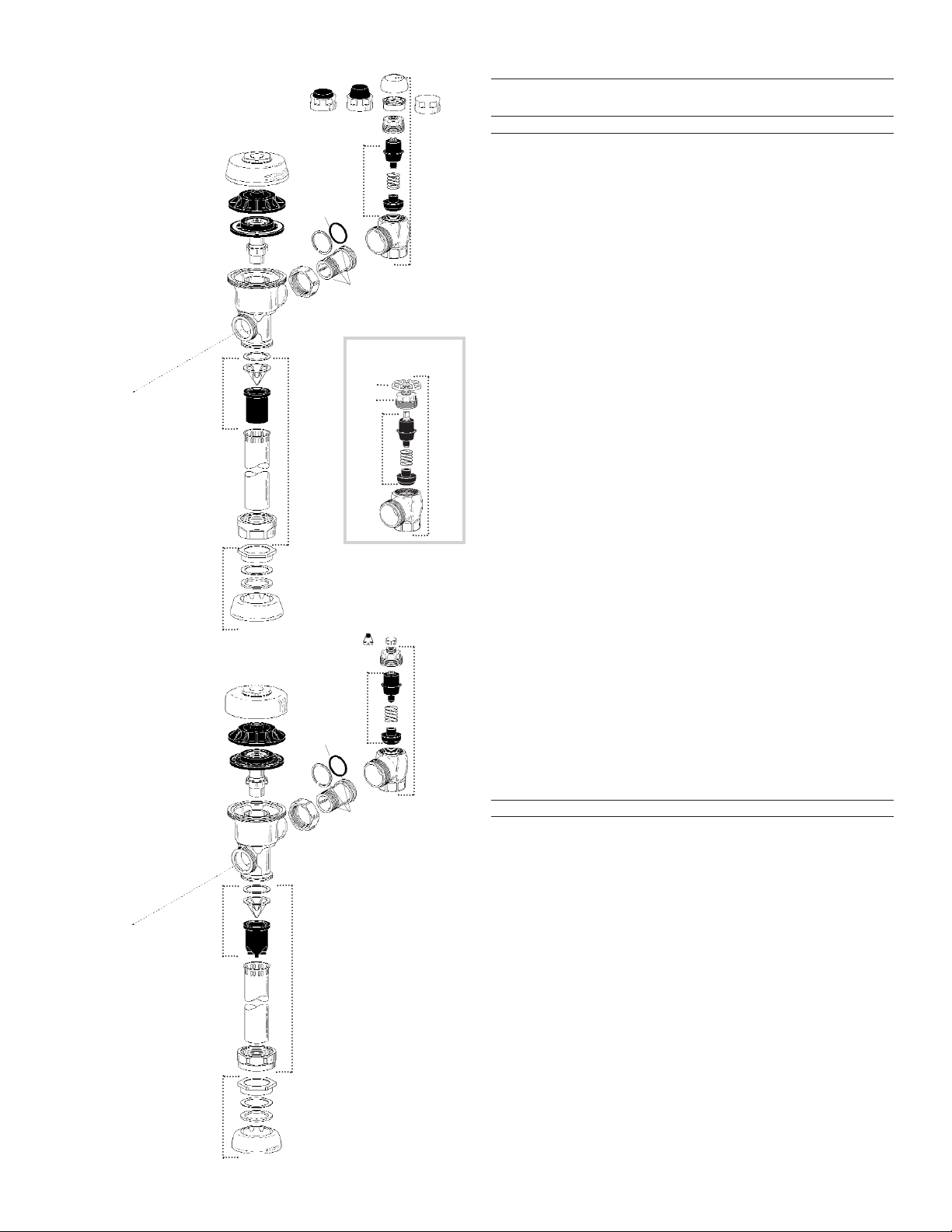
ROYAL
Installation
Royal
Code No. Part No. Part/Assembly
22 0301172 A-72 CP Cover
23 0301168 A-71 Inside Cover
24 SEE DIAPHRAGM ASSEMBLY CHART ON PAGE 4
25 3323182 V-651-A Vacuum Breaker Repair Kit
26 0393004 V-600-AA 3/4" (19 mm) x 9" (229 mm) CP Vacuum Breaker
0393006 V-600-AA 1-1/4" (32 mm) x 9" (229 mm) CP Vacuum Breaker
0393007 V-600-AA 1-1/2" (38 mm) x 9" (229 mm) CP Vacuum Breaker
27 0306125 F-5-AW 3/4" (19 mm) CP Spud Coupling Assembly
0306140 F-5-AU 1-1/4" (32 mm) CP Spud Coupling Assembly
0306146 F-5-AT 1-1/2" (38 mm) CP Spud Coupling Assembly
28 0308676 H-550 CP Stop Coupling
29 0308801 H-551-A CP Adjustable Tail 2-1/16" (52 mm) long
30 5308696 H-553 “O” Ring - 24 per pkg.
31 3308386 H-700-A 1" (25 mm) Screwdriver Bak-Chek
®
Angle Stop
CP - complete
3308384 H-700-A 3/4" (19 mm) Screwdriver Bak-Chek
®
Angle Stop
CP - complete
32 3308853 H-541-A-SD Control Stop Repair Kit
for use with 1" (25 mm) & 3/4" (19 mm) H-700-A , 1" (25 mm) H-600-A,
1" (25 mm) & 3/4" (19 mm) H-740-A and 1" (25 mm) H-540-A SD Stops
3308856 H-543-A-SD Control Stop Repair Kit
for use with 3/4" (19 mm) H-600-A and H-540-A SD Stops
33 0308612 H-622 CP Bonnet
for use with 1" (25 mm) & 3/4" (19 mm) H-700-A and 1" (25 mm) H-600-A
SD Stops
0308843 H-577 CP Bonnet
for use with 3/4" (19 mm) H-600-A SD Stops
34 3308791 H-1010-A 1" (25 mm) Vandal Resistant Control Stop Cap Assembly
for use with 1" (25 mm) & 3/4" (19 mm) H-700-A and 1" (25 mm) H-600-A
SD Stops
3308790 H-1009-A 3/4" (19 mm) Vandal Resistant Control Stop Cap Assembly
for use with 3/4" (19 mm) H-600-A SD Stops
35 0308840 H-573 1" (25 mm) Control Stop Cap CP
for use with 1" (25 mm) & 3/4" (19 mm) H-700-A and 1" (25 mm) H-600-A
SD Stops
0308848 H-582 3/4" (19 mm) Control Stop Cap CP
for use with 3/4" (19 mm) H-600-A SD Stops
36 3308866 H-574 1" (25 mm) Control Stop Cap with Bumper
for use with 1" (25 mm) & 3/4" (19 mm) H-700-A and 1" (25 mm) H-600-A
SD Stops
37 3308867 H-576 1" (25 mm) Control Stop Cap with Extended Bumper
for use with 1" (25 mm) & 3/4" (19 mm) H-700-A and 1" (25 mm) H-600-A
SD Stops
38 3308860 H-1006-A Repair Kit for 1" (25 mm) Stops with Concealed WH
for use with 1" (25 mm) H-700, H-600, and H-540 WH Series Stops
3308859 H-1007-A Repair Kit 3/4" (19 mm) Stops with Concealed WH
for use with 3/4" (19 mm) H-700 WH Series Stops
39 0388010 H-730-A 1" (25 mm) Concealed WH Bak-Chek®Angle Stop RB
0388011 H-730-A 3/4" (19 mm) Concealed WH Bak-Chek
®
Angle Stop RB
39A 3308872 H-1011-A Repair Kit (for Concealed WH only; does not include bonnet)
39B 0208083 H-623 Bonnet
0308705 H-561 Bonnet
Regal
Code No. Part No. Part/Assembly
23 0301168 A-71 Inside Cover
28 0308676 H-550 CP Stop Coupling
29 0308801 H-551-A CP Adjustable Tail 2-1/16" (52 mm) long
30 5308696 H-553 “O” Ring - 24 per pkg.
32 3308853 H-541-A-SD Control Stop Repair Kit
for use with 1" (25 mm) & 3/4" (19 mm) H-700-A ,1" (25 mm) H-600-A,
1" (25 mm) & 3/4" (19 mm) H-740-A and 1" (25 mm) H-540-A SD Stops
3308856 H-543-A-SD Control Stop Repair Kit
for use with 3/4" (19 mm) H-600-A and H-540-A SD Stops
40 0317004 R-10 CP Cover
41 SEE INSIDE PARTS ASSEMBLY CHART ON PAGE 4
42 3323192 V-551-A Vacuum Breaker Repair Kit
43 0323005 V-500-AA 3/4" (19 mm) x 9" (229 mm) CP Vacuum Breaker
0323006 V-500-AA 1-1/4" (32 mm) x 9" (229 mm) CP Vacuum Breaker
0323007 V-500-AA 1-1/2" (38 mm) x 9" (229 mm) CP Vacuum Breaker
44 0306102 F-54-A 3/4" (19 mm) CP Spud Coupling Assembly
0306142 F-55-A 1-1/4" (32 mm) CP Spud Coupling Assembly
0306145 F-56-A 1-1/2" (38 mm) CP Spud Coupling Assembly
45 0388029 H-740-A 1" (25 mm) SD Bak-Chek
®
Stop CP - complete
0388031 H-740-A 3/4" (19 mm) SD Bak-Chek
®
Stop CP - complete
46 0308991 H-639 CP Bonnet
for use with H-740-A 1" (25 mm) & 3/4" (19 mm) and H-540-A 1" (25 mm)
SD Stops
0308601 H-538 CP Bonnet
for use with H-540-A 3/4" (19 mm) SD Stops
47 5308156 H-37 CP Cap (package of 6)
48 5310034 J-2/J-7 Bumper Assembly (package of 6)
Valve Parts List
NOTE: Also refer to the Royal, Regal, Control Stop and Flush Connection Maintenance Guides.
REGAL
Installation
3
22
23
24
Valve Body
25
27
26
28
29
30
31
32
33
35
34
3736
23
40
Valve Body
41
42
44
43
28
29
30
45
32
47
48
46
To Solenoid
To Solenoid
The Repair Kits and Parts listed
on these pages are designed to
service all Sloan OPTIMA
Diaphragm type Flushometers,
including those manufactured for
Low Consumption (LC) usage.
Each item has been identified by
a specific Part Number (in italics)
with a corresponding Code
Number (in bold). To expedite
your replacement requirements,
order by Code Number.
ABBREVIATIONS:
CP . . . . . .Chrome Plated
RB . . . . . . .Rough Brass
SD . . . . . . . .Screwdriver
WH . . . . . .Wheel Handle
gpf . . . .gallons per flush
Lpf . . . . . .Liters per flush
39
38
39A
39B
Concealed WH
Page 4
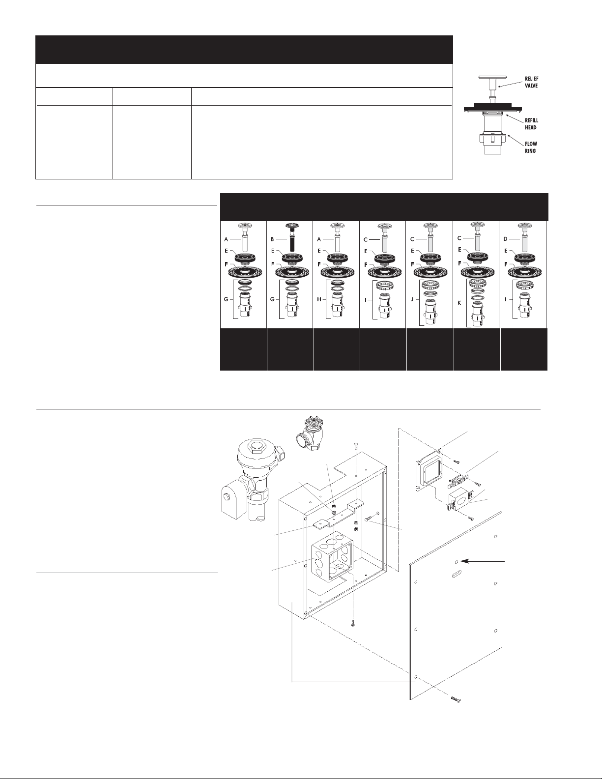
Wall Box Kits
4
Closet Models
— 3305180 EL-192-A Closet Wall Box Kit - Stainless Steel
Includes four EL-125 Mounting Screws, four
EL-126 Hex Nuts, four EL-127 Lock Washers,
EL-195 Mounting Bracket, EL-196 Electrical
Box, EL-197 Electrical Box Cover, EL-141-A
Override Switch Subassembly, EL-216 Wall
Box 13" x 17" (330 mm x 432 mm) with
14.5” x 18.5” (368 mm x 470 mm)
Stainless Steel Wall Box Cover with hole for
override switch, EL-318 Spanner Bit,
EL-1500-L Closet Sensor Replacement
Kit, and four WB-6 Screws.
— 3305179 EL-192-A Closet Wall Box Kit - Polished Brass
Includes the same components as 3305180
listed above except unit is furnished with
Polished Brass 14.5" x 18.5" (368 mm x
470 mm) Wall Box Cover (instead of
Stainless Steel).
Urinal Models
— 3305178 EL-191-A Urinal Wall Box Kit - Stainless Steel
Includes four EL-125 Mounting Screws,
four EL-126 Hex Nuts, four EL-127 Lock
Washers, EL-193 Wall Box 13" x 17"
(330 mm x 432 mm) with 14.5” x 18.5”
(368 mm x 470 mm) Stainless Steel Wall
Box Cover, EL-195 Mounting Bracket,
EL-196 Electrical Box, EL-197 Electrical Box
Cover, EL-318 Spanner Bit, EL-1500 Urinal
Sensor Replacement Kit, and four WB-6
Screws.
— 3305177 EL-191-A Urinal Wall Box Kit - Polished Brass
Includes the same components as 3305178
listed above except unit is furnished with
Polished Brass 14.5" x 18.5" (368 mm x
470 mm) Wall Box Cover (instead of
Stainless Steel).
Royal ESS
item 24 - Dual Filtered Diaphragm™ Assembly •••
Sold ONLY in ROYAL Performance™ Kits
A-36-A
3301036
4.5 gpf/17.0 Lpf
CLOSET
A-37-A
3301037
1.5 gpf/5.7 Lpf
URINAL
A-38-A
3301038
3.5 gpf/13.2 Lpf
CLOSET
A-41-A
3301041
1.6 gpf/6.0 Lpf
CLOSET
A-42-A
3301044
1.0 gpf/3.8 Lpf
URINAL
A-43-A
3301081
0.5 gpf/1.9 Lpf
URINAL
A-44-A
3301024
2.4 gpf/9.0 Lpf
CLOSET
ESS KIT includes: EL-128-A Actuator Cartridge Assembly (item 1A); Dual Filtered Diaphragm Assembly (item 24); High Back Pressure Vacuum Breaker
Repair Kit (item 25); and one Tailpiece “O” Ring (item 30). DIAPHRAGM ONLY KIT includes: Dual Filtered Diaphragm Assembly (item 24) ONLY
ESS KIT DIAPHRAGM ONLY KIT
Code No. Kit No. Code No. Kit No. Flush Volume Use With Relief Valve Refill Head* Flow Ring
A 3345013 EL-1101-A 3301502 A-1041-A 1.6 gpf/6.0 Lpf Low Consumption Water Closets Green Gray Smooth
B 3345014 EL-1102-A 3301501 A-1038-A 3.5 gpf/13.2 Lpf Water Saver Water Closets White Gray Smooth
C 3345015 EL-1103-A 3301505 A-1044-A 2.4 gpf/9.0 Lpf 9 Liter European Water Closets Blue Gray Smooth
D 3345016 EL-1106-A 3301504 A-1043-A 0.5 gpf/1.9 Lpf Wash Down Urinals Green Black Smooth & Slotted
E 3345017 EL-1107-A 3301503 A-1042-A 1.0 gpf/3.8 Lpf Low Consumption Urinals Green Black Slotted
F 3345018 EL-1108-A 3301500 A-1037-A 1.5 gpf/5.7 Lpf Water Saver Urinals Black Black Smooth
Regal Inside Parts List**
A 5301058 A-19-AC Relief Valve, White (Closet)
B 5301059 A-19-AU Relief Valve, Black (Urinal)
C 5301211 A-19-ALC Relief Valve, Green
(Closet/Urinal-Low Consumption)
D 5301143 A-19-AL Relief Valve, Blue (9 Liter Closet)
E 5301111 A-15-A Disc
F 5301188 A-156-A Diaphragm
G 5301236 A-163-A Guide Assembly
4.5 gpf/17.0 Lpf Closet and
1.5 gpf/5.7 Lpf Urinal
H 5301032 A-152-A Guide Assembly
3.5 gpf/13.2 Lpf Closet
I 5301031 A-151-A Guide Assembly
1.6 gpf/6.0 Lpf Closet
J 5301155 A-155-A Guide Assembly
1.0 gpf/3.8 Lpf Urinal
K 5301157 A-157-A Guide Assembly
0.5 gpf/1.9 Lpf Urinal
To identify the Flush Volume of a
DUAL FILTERED DIAPHRAGM
ASSEMBLY, look at the color of
the Relief Valve, the Refill Head
and the shape of Flow Ring.
*NOTE: Water Closet Refill
Heads (Gray) have larger slots
than Urinal Refill Heads (Black).
**NOTE: All Regal inside part items are supplied in packages of 12.
Regal ESS
item 41- Inside Parts Kits Assembly
EL-125
EL-126
EL-127
EL-195
EL-196
EL-216 Closet
EL-193 Urinal
EL-125
EL-197
EL-141
EL-1500-L Closet
EL-1500 Urinal
WB-6
Panel shown
with hole for
Override
Switch (Closet
applications
only)
Page 5
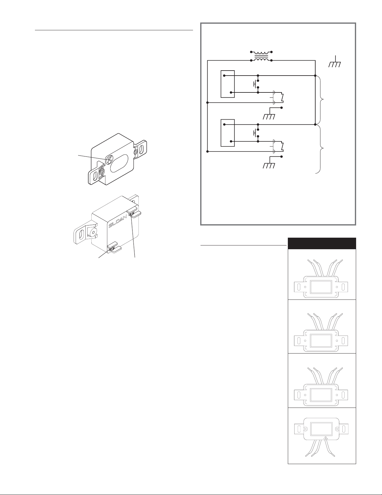
Sensor Replacement
NOTE: The EL-1500 Series OPTIMA Sensor (a two-wire unit) replaces the older EL-150 Series
Sensors (either three-wire or four-wire units). Refer to the Wiring History shown below.
IMPORTANT
• Be certain to disconnect the 24 VAC power supply either at the transformer or
the fuse box. Failure to disable the power supply can result in damage to the
EL-1500 Series Sensor.
• The Solenoid Operator must be removed from the Valve on exposed urinal
installations. Do not damage the O-ring seal on the operator assembly.
1 Remove the Cover Plate (for Wall Box Installation, remove Cover Panel) and
old Sensor from the wall installation. Use a 5/64" hex wrench to remove the
Cover Plate Screws (or #8 drilled spanner head screwdriver EL-318 to
remove the vandal-resistant screws from the Wall Box Cover Panel.)
2 Connect one 24 VAC lead to the Sensor Terminal labeled “24 VAC IN”
(see Figure 1B).
• On an old three-wire EL-150 series Sensor, this wire was connected to the
BLACK Sensor lead.
• On an old four-wire EL-150 series Sensor, this wire was connected to the
BROWN Sensor lead.
3 Connect one Solenoid Lead to the Sensor Terminal labeled “TO VALVE”
(see Figure 1B).
• On an old three-wire or four-wire EL-150 Series Sensor, this wire was
connected to the RED Sensor Lead.
4 Connect the remaining 24 VAC lead to the remaining Solenoid Lead.
• On an old three-wire EL-150 Series Sensor, these wires were connected to
the WHITE Sensor Leads.
• On an old four-wire EL-150 Series Sensor, these wires were connected to
the YELLOW and BLUE (or in very early models, the inner BROWN)
Sensor Leads.
5 On Water Closet installations only, connect the Override Button (shown as the
Override Switch in Wiring Diagram) parallel to the EL-1500-L Sensor.
6 Reinstall the Sensor with the Orientation Arrow on the Lens side of the Sensor
pointing UP (see Figure 1A). Replace the Cover Plate (or Wall Box Panel) and
tighten the Cover Plate (or Wall Box Panel) Screws.
7 Reconnect the 24 VAC power supply at the transformer or the fuse box.
Start-Up Mode
NOTE: It is important that only permanent targets
are present at this time.
The self-adaptive sensor automatically
adjusts to the surrounding environment when
the 24 volt supply is activated. No manual
adjustment is required. The start-up cycle
completes in approximately five (5)
minutes. A continuous red light visible in the
Sensor Window indicates the Start-up Mode.
If the red light flashes, the Sensor detects a
target. Unless this target is a permanent
fixture in the Sensor’s environment
(i.e., a wall or stall door), it must be
removed from the view of the Sensor. If a
target is permanent, the Sensor will adapt
itself around this target. In this case, the
Start-Up Mode may take up to 10 (ten)
minutes. When the Start-Up cycle is
complete, the red light will no longer be
visible in the Sensor Window.
NOTE: If the 24 volt power supply is ever
interrupted for longer than fifteen (15) seconds,
the start-up mode begins automatically when
power is restored.
Incorrect wiring or a short in the 24 volt
power supply will initiate a warning signal
in the Sensor Window. The visible light
flashes a continuous “S-O-S” signal:
three (3) slow, three (3) fast, and three (3)
slow flashes.
WIRING DIAGRAM
NOTE: A MAXIMUM OF TEN (10) SENSOR FLUSHOMETER UNITS CAN OPERATE
FROM ONE (1) SLOAN EL-154 TRANSFORMER. CL ASS 2 UL LISTED, 48 VA (MIN.)
AT 24 VAC, PLATE MOUNTED.
Figure 2
“24 VAC IN”
CONNECTION
“TO VALVE”
CONNECTION
Figure 1B
5
* OVERRIDE SWITCH USED WITH
WATER CLOSETS ONLY
Release date 03/09/78
brown
brown
red
red
Release date 08/11/83
brown
brown
red
red
with
yellow or
all yellow
Release date 02/02/87
brown
blue
red
yellow
Release date 12/12/90
red
black
white
EL-150 Wiring History
for 4-wire and 3-wire sensors
ORIENTATION
ARROW
Figure 1A
120 VAC
24 VAC
COMMON
GND
EL-1500 SERIES
SENSOR
OVERRIDE
SWITCH*
24 VAC COIL
COIL WIRE
UNIT #1
GROUND
SCREW IN
SOLENOID
HOUSING
EL-1500 SERIES
SENSOR
OVERRIDE
SWITCH*
24 VAC COIL
COIL WIRE
GROUND
SCREW IN
SOLENOID
HOUSING
UNIT #2
THRU #10
(IF USED)
Page 6
1. PROBLEM: Valve does not function (red light does not
flash when user steps in front of sensor).
CAUSE: No power is being supplied to sensor.
SOLUTION: Ensure that the main power is turned “ON”. Check
transformer, leads and connections. Repair or
replace as necessary.
CAUSE: EL-1500/EL-1500-L Sensor is not operating.
SOLUTION: Replace EL-1500/EL-1500-L Sensor.
2. PROBLEM: Valve does not function (red light flashes
when user steps in front of Sensor).
INDICATOR: The red light stops flashing when user steps away and the valve
makes a “clicking” sound but does NOT flush.
CAUSE: No water is being supplied to the valve.
SOLUTION: Make cer tain that water supply is turned “ON” and the
Control Stop is open.
CAUSE: EL-128-A cartridge is fouled or jammed.
SOLUTION: Turn electronic power to valve “OFF” (failure to do so
could result in damage to the solenoid coil). Remove
the solenoid operator from the valve and remove the
EL-128-A cartridge. Clean and/or repair as necessary.
INDICATOR: The red light stops flashing when user steps away but the valve
does NOT make a “clicking” sound and does NOT flush.
CAUSE: EL-163-A solenoid shaft assembly is fouled or jammed.
SOLUTION: Turn electronic power to valve “OFF” (failure to do so
could result in damage to the solenoid coil). Remove
EL-101 or EL-166 nut from the solenoid operator.
Remove the coil from the solenoid operator. Use a
spanner wrench or pliers to remove the EL-163-A
solenoid shaft assembly from valve. Clean and/or
replace as necessary. Be sure to replace plunger
spring when reassembling Solenoid Shaft Assembly.
INDICATOR: The red light flashes three (3) short flashes, three (3) long
flashes then three (3) short flashes (“S-O-S”) and continues to
repeat this cycle even when user steps out of the sensor’s
detection range.
CAUSE: EL-1500/EL-1500-L Sensor wiring connections are
incorrect.
SOLUTION: Rewire Sensor to valve. One solenoid lead connects to the
“TO VALVE” connection on Sensor. One transformer lead
connects to the “24 VAC IN” connection on Sensor.
Second solenoid lead and second transformer lead
connect together.
CAUSE: Wiring to Sensor is ground shorted.
SOLUTION: Find short in wiring circuit and correct.
CAUSE: EL-162-2 solenoid coil is burnt out or coil is not
connected to solenoid plunger shaft.
SOLUTION: Reinstall or replace coil as necessary.
3. PROBLEM: Volume of water is insufficient to adequately siphon fixture.
CAUSE: Control Stop is not open wide enough.
SOLUTION: Adjust control stop for desired water delivery.
CAUSE: Low Consumption unit is installed on Water Saver or
Conventional fixture.
SOLUTION: Replace Diaphragm component parts of valve with kit
that corresponds to appropriate flush volume of fixture.
CAUSE: Inadequate water volume or pressure available from supply.
SOLUTION: Increase pressure or supply (flow rate) to the valve.
Consult factory for assistance.
4. PROBLEM: Length of flush is too long (long flushing) or valve
fails to shut off.
CAUSE: Water Saver valve is installed on Low Consumption fixture.
SOLUTION: Replace Diaphragm component par ts of valve with
kit that corresponds to appropriate flush volume of fixture.
CAUSE: Relief valve in diaphragm is not seated properly or
bypass hole in diaphragm is clogged.
SOLUTION: Disassemble inside Diaphragm component par ts and
wash parts thoroughly. Replace worn parts if necessary.
5. PROBLEM: Water splashes from fixture.
CAUSE: Supply flow rate is more than necessary.
SOLUTION: Adjust Control Stop to meet flow rate required for proper
cleansing of the fixture.
CAUSE: Closet valve is installed on urinal fixture.
SOLUTION: Replace closet Diaphragm component par ts with proper
urinal kit (Inside Diaphragm Assembly or Inside Parts Kit)
Troubleshooting Guide
NOTE: Upon detection of the user, the red indicator light flashes slowly for a period of eight seconds. When the user leaves the detection range, the indicator light flashes rapidly and the
Sensor initiates the flush sequence. Then the indicator light stops flashing and the valve flushes. (On water closet models, the valve will flush after a three-second delay).
Maintenance Guide
•SENSOR OPERATED VALVES
Care and Cleaning Instructions
DO NOT USE abrasive or chemical cleaners to clean
Flushometers that may dull the luster and attack the chrome
or special decorative finishes. Use ONLY soap and water, then
wipe dry with a clean towel or cloth.
When cleaning the bathroom tile, protect the Flushometer
from any splattering of cleaner. Acids and cleaning fluids
can discolor or remove chrome plating.
If further assistance is required, please contact the
Sloan Valve Company Installation Engineering Department at
1-888-SLOAN-14.
SLOAN VALVE COMPANY • 10500 SEYMOUR AVENUE • FRANKLIN PARK, IL 60131
Phone: 1-800-9-VALVE-9 or 1-847-671-4300 • Fax: 1-800-447-8329 or 1-847-671-4380 • http://www.sloanvalve.com
Copyright © 2003 Sloan Valve Company Printed in the U.S.A. Made in the U.S.A. OPTIMA ESS M.G. — Rev. 0a (05/03) Code No. 0816510
The information contained in this document is subject to change without notice.
 Loading...