

Page 1
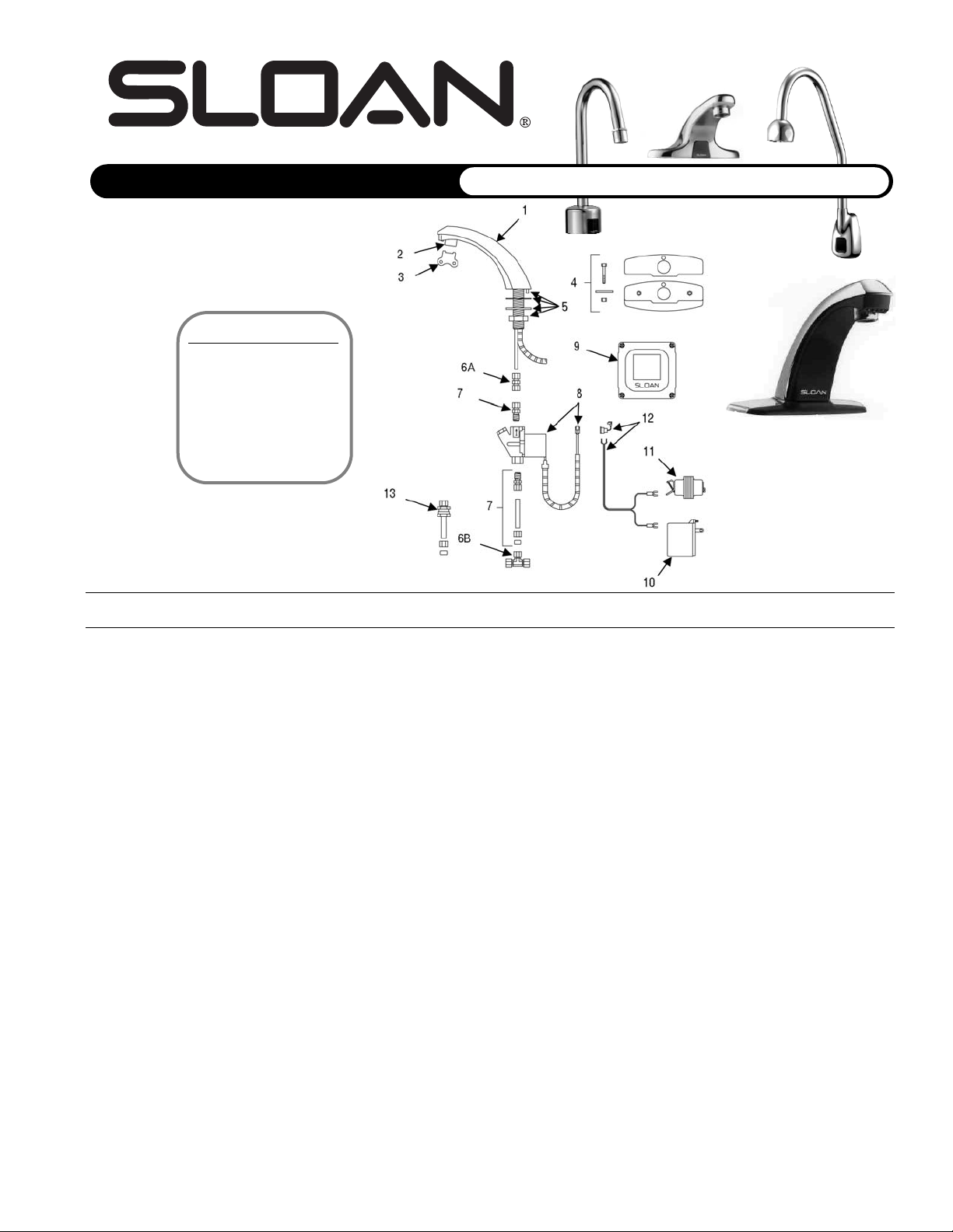
Parts List—ETF-80 Faucet
Item Code Part Description
Number Number Number
1 0305613 ETF-250-A Faucet and Sensor Assembly (ETF-80)
3305536 ETF-398-A Fiber Optic Sensor Assembly Only
2 3365091 ETF-1021-A 0.5 gpm (1.9 Lpm) Spray Head with Key (female thread)
3365090 ETF-1022-A 2.2 gpm (8.3 Lpm) Aerator Spray Head with Key (female thread)
0305612 ETF-237 2.2 gpm (8.3 Lpm) Laminar Flow Spray Head (female thread)
3 0305927 ETF-435 Replacement Key ONLY for ETF-1021-A Spray Head and ETF-1022-A Aerator Spray Head
(NOT required for ETF-237 Laminar Flow Spray Head)
4 3365466 ETF-295-A 4” (102 mm) Centerset Trim Plate Kit for Faucet (Faucet Only) includes two (2) Nuts, two (2) Hex Screws, two (2) Flat Washers,
Single Hole Cover Plate, and CP Base Plate
— 3365467 ETF-299-A 4” (102 mm) Centerset Trim Plate Kit for Faucet with Optional Mixing Valve includes two (2) Nuts, two (2) Hex Screws, two (2) Flat
Washers, Dual Hole Cover Plate, and CP Base Plate (not shown)
5 0305626 ETF-290-A Faucet Mounting Kit includes Rubber Gasket, Mounting Washer, Mounting Nut, and ETF-297 Compression Fitting Connector
6A 0305736 ETF-297 1/4” to 3/8” Compression Fitting Connector
6B 0305728 ETF-259 3/8” Tee Compression Fitting
7 3365676 ETF-437-A Single Solenoid Supply Kit includes Supply Tube, two (2) ETF-61 Compression Fittings, Compression Nut, and Ferrule
8 0305849 ETF-370-A 24 VAC Solenoid Valve Assembly includes 18” (153 mm) armored Cable and two (2) Terminal Housings
9 3365000 ETF-450-A Control Module Assembly includes splashproof Junction Box and Junction Box Mounting Kit
10 0365534 ETF-233 120V/35VA Plug-In Transformer
11 0345370 EL-248-40 24V/40 VA Box Mount Transformer
12 0365001 ETF-458-A Input Power Cable (Transformer to Control Module) includes Strain Relief and two (2) Terminal Crimp Connectors
13 3365001 ETF-470-A Back Check
— 3305560 ETF-1006-A Repair Kit for old-style ETF-80 Faucets (manufactured before 1993) includes Hex Screw, 5/64” Hex Wrench, Cable Assembly, Hose
Clamp, 5-connector Housing, ETF-435 Key for Spray Heads, Access Plate/Sensor Assembly, and ETF-450-A Control Module Assy.
— 3305577 ETF-1009-A Solenoid Valve Repair Kit includes Replacement Filter
FAUCET CABLE EXTENSION CORDS
— 0365042 ETF-1005-26 Faucet to Control Module Extension Cord; 26 inch (0.7 meter) Length
— 0365861 ETF-1005-36 Faucet to Control Module Extension Cord; 36 inch (0.9 meter) Length
— 0305862 ETF-1005-72 Faucet to Control Module Extension Cord; 72 inch (1.8 meter) Length
— 0305863 ETF-1005-108 Faucet to Control Module Extension Cord; 108 inch (2.7 meter) Length
— 0365838 ETF-1003-36 Solenoid to Control Module Extension Cord; 36 inch (0.9 meter) Length
— 0365053 ETF-1003-48 Solenoid to Control Module Extension Cord; 48 inch (1.2 meter) Length
— 0365839 ETF-1003-72 Solenoid to Control Module Extension Cord; 72 inch (1.8 meter) Length
— 0365840 ETF-1003-108 Solenoid to Control Module Extension Cord; 108 inch (2.7 meter) Length
Old-Style Faucets
ETF-80 faucets manufactured
before 1992 had all their electronic circuitry located within
the body of the spout.
Replacement parts (including
sensor components) are
available in ETF-1006-A Repair
Kits (3305560).
SLOAN VALVE COMPANY • 10500 SEYMOUR AVENUE • FRANKLIN PARK, IL 60131
Phone: 1-800-9-VALVE-9 1-847-671-4300 • Fax: 1-800-447-8329 1-847-671-4380 • http://www.sloanvalve.com
Copyright © 2004 Sloan Valve Company Printed in U.S.A. Made in U.S.A. OPTIMA FAU M.G. — Rev. 0a (03/04) Code No 0816519
SENSOR FAUCETS
PP aa rr tt ss GG uu ii dd ee
•24 VAC HARDWIRE FAUCETS
OPTIMA ETF-80 Faucet
Page 2
OPTIMA ETF-500 Faucet
SENSOR FAUCETS
PP aa rr tt ss GG uu ii dd ee
•24 VAC HARDWIRE FAUCETS
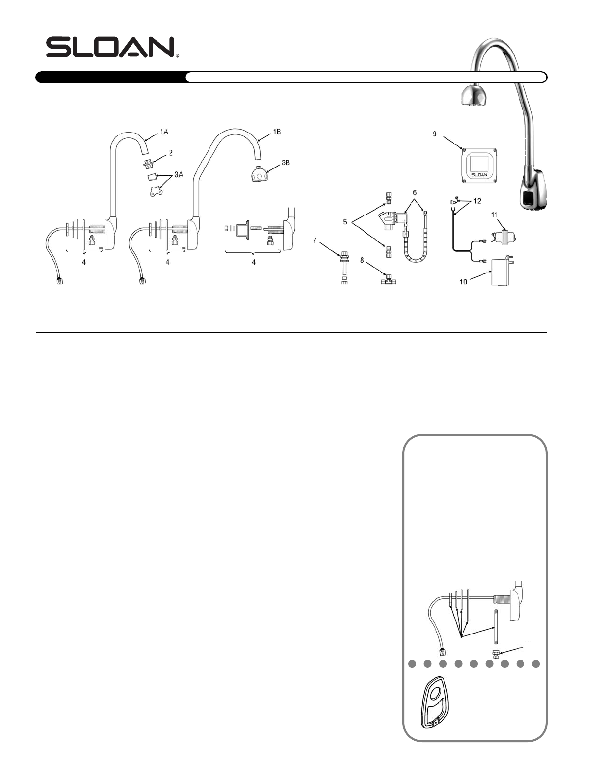
Parts List—ETF-500 Faucet
Item Code Par t Description
Number Number Number
1A 0365111 ETF-561-A Faucet/Sensor Assembly with Standard Gooseneck Spout (ETF-500)
1B 0365112 ETF-564-A Faucet/Sensor Assembly with Surgical Bend Gooseneck Spout (ETF-500-S)
— 0365097 ETF-568-A Sensor Housing and Cable Assembly for ETF-500 and ETF-500-S Faucets
2 0305784 ETF-178 Aerator Adapter for Spray Heads (not required for AC-55-A Shower Spray Head)
3A 3365091 ETF-1021-A 0.5 gpm (1.9 Lpm) Spray Head with Key (female thread)
3365090 ETF-1022-A 2.2 gpm (8.3 Lpm) Aerator Spray Head with Key (female thread)
0305612 ETF-237 2.2 gpm (8.3 Lpm) Laminar Flow Spray Head (female thread)
0305927 ETF-435 Replacement Key ONLY for ETF-1021-A Spray Head and ETF-1022-A Aerator Spray Head
(NOT required for ETF-237 Laminar Flow Spray Head)
3B 0328134 AC-55-A Shower Spray Head Assembly, 2.2 gpm (8.3 Lpm)
4 0315060 EBF-110-A Faucet Mounting Kit includes Base Gasket, large Flat Washer, large
Lockwasher, large Nut, Mounting Spacer, Mounting Stud, small Flat Washer,
small Lockwasher, small Nut, Anti-Rotation Screw, and ETF-591 Compression
Fitting Connector (male)
0365152 ETF-591 1/8” NPT Pipe to 3/8” Tube Male Compression Fitting Connector
5 3365676 ETF-437-A Single Solenoid Supply Kit includes Supply Tube, two (2) ETF-61
Compression Fittings, Compression Nut, and Ferrule
6 0305849 ETF-370-A 24 VAC Solenoid Valve Assembly includes 18” (153 mm) armored Cable and
two (2) Terminal Housings
7 3365001 ETF-470-A Back Check
8 0305728 ETF-259 3/8” Tee Compression Fitting
9 3365000 ETF-450-A Control Module Assembly includes splashproof Junction Box and Junction
Box Mounting Kit
10 0365534 ETF-233 120V/35VA Plug-In Transformer
11 0345370 EL-248-40 24V/40VA Box Mount Transformer
12 0365001 ETF-458-A Input Power Cable (Transformer to Control Module) includes Strain Relief and
two (2) Terminal Crimp Connectors
13 n/a EBF-110-A
Old Faucet Mounting Kit included 3/8” Water Supply Tube, Base Gasket, large
Flat Washer, large Lockwasher, large Nut, and ETF-547 Compression Fitting
Connector (order items 4 and 14 as replacement parts)
14 0365058 ETF-547 1/8” NPT Pipe to 3/8” Tube Female Compression Fitting Connector
— 3305577 ETF-1009-A Solenoid Valve Repair Kit includes Replacement Filter
FAUCET CABLE EXTENSION CORDS
— 0365042 ETF-1005-26 Faucet to Control Module Extension Cord; 26 inch (0.7 meter) Length
— 0365861 ETF-1005-36 Faucet to Control Module Extension Cord; 36 inch (0.9 meter) Length
— 0305862 ETF-1005-72 Faucet to Control Module Extension Cord; 72 inch (1.8 meter) Length
— 0305863 ETF-1005-108 Faucet to Control Module Extension Cord; 108 inch (2.7 meter) Length
— 0365838 ETF-1003-36 Solenoid to Control Module Extension Cord; 36 inch (0.9 meter) Length
— 0365053 ETF-1003-48 Solenoid to Control Module Extension Cord; 48 inch (1.2 meter) Length
— 0365839 ETF-1003-72 Solenoid to Control Module Extension Cord; 72 inch (1.8 meter) Length
— 0365840 ETF-1003-108 Solenoid to Control Module Extension Cord; 108 inch (2.7 meter) Length
Mounting Kit and Faucet Shank
The new mounting kit (in production since June
1999; part 4 shown on the left) includes parts for
installation on both thin and thick surfaces, an
ETF-591 male compression fitting, and an antirotation screw for installation on sheet metal surfaces less than 0.41” (10 mm) thick. For surfaces
between 0.41” (10 mm) and 1.00” (25 mm)
thick, use the mounting spacer and mounting stud
hardware*. The faucet sensor cable is threaded
through a groove on the side of the shank.
The older mounting kit (part 13 shown below) can
be identified by a copper supply tube attached to
the faucet shank., requires an ETF-547 compres-
sion fitting, and threads the faucet sensor cable
through the interior of the shank.
13
14
New Base Gasket
The new base gasket (in production since October 1999)
is shown at left. An older base
gasket design did not have
the u-shaped drainage hole.
* To mount faucet on a surface between
0.41” (10 mm) and 1.00” (25 mm) thick,
use the hardware shown above.
2
Page 3
SENSOR FAUCETS
PP aa rr tt ss GG uu ii dd ee
24 VAC HARDWIRE FAUCETS•
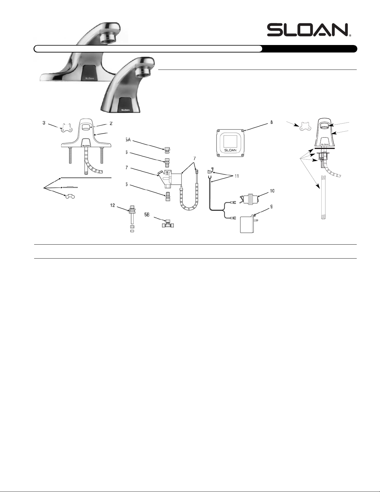
Parts List—ETF-600 and ETF-610 Faucets
Item Code Part Description
Number Number Number
1A 0365086 ETF-543-A Faucet and Sensor Assembly (ETF-600)
1B 0365117 ETF-570-A Pedestal Faucet and Sensor Assembly (ETF-610)
— 0365070 ETF-542-A Sensor Module Only (for ETF-600 and ETF-610 faucets) includes 18” (153 mm) armored Cable, Shroud, and Housing for
Sensor Window
2 3365092 ETF-1023-A 0.5 gpm (1.9 Lpm) Spray Head with Key (male thread)
3365093 ETF-1024-A 2.2 gpm (8.3 Lpm) Aerator Spray Head with Key (male thread)
0305607 F-175-L 2.2 gpm (8.3 Lpm) Laminar Flow Spray Head (male thread)
3 0305927 ETF-435 Replacement Key Only for ETF-1023-A Spray Head and ETF-1024-A Aerator Spray Head
(NOT required for F-175-L Laminar Flow Spray Head)
4A 3365088 ETF-546-A Faucet Mounting Kit for ETF-600 includes Base Gasket, two (2) Slotted Mounting Washers, two (2) Wing Nuts, and ETF-547
Compression Fitting Connector
4B 0315085 EBF-123-A Faucet Mounting Kit for ETF-610 includes Spacer, Base Gasket, 1/4” NPSM Hex Nut, Washer, 9/16” Lockwasher, ETF-547
Compression Fitting Connector, and 3/8” RB Water Supply Tube
5A 0365058 ETF-547 1/8” NPT Pipe to 3/8” Tube Compression Fitting Connector (female)
5B 0305728 ETF-259 3/8” Tee Compression Fitting
6 3365676 ETF-437-A Single Solenoid Supply Kit includes Supply Tube, two (2) ETF-61 Compression Fittings, Compression Nut, and Ferrule
7 0305849 ETF-370-A 24 VAC Solenoid Valve Assembly includes 18” (153 mm) armored Cable and two (2) Terminal Housings
8 3365000 ETF-450-A Control Module Assembly includes splashproof Junction Box and Junction Box Mounting Kit
9 0365534 ETF-233 120V/35VA Plug-In Transformer
10 0345370 EL-248-40 24V/40VA Box Mount Transformer
11 0365001 ETF-458-A Input Power Cable (Transformer to Control Module) includes Strain Relief and two (2) Terminal Crimp Connectors
12 3365001 ETF-470-A Back Check
— 3305577 ETF-1009-A Solenoid Valve Repair Kit includes Replacement Filter
FAUCET CABLE EXTENSION CORDS
— 0365042 ETF-1005-26 Faucet to Control Module Extension Cord; 26 inch (0.7 meter) Length
— 0365861 ETF-1005-36 Faucet to Control Module Extension Cord; 36 inch (0.9 meter) Length
— 0305862 ETF-1005-72 Faucet to Control Module Extension Cord; 72 inch (1.8 meter) Length
— 0305863 ETF-1005-108 Faucet to Control Module Extension Cord; 108 inch (2.7 meter) Length
— 0365838 ETF-1003-36 Solenoid to Control Module Extension Cord; 36 inch (0.9 meter) Length
— 0365053 ETF-1003-48 Solenoid to Control Module Extension Cord; 48 inch (1.2 meter) Length
— 0365839 ETF-1003-72 Solenoid to Control Module Extension Cord; 72 inch (1.8 meter) Length
— 0365840 ETF-1003-108 Solenoid to Control Module Extension Cord; 108 inch (2.7 meter) Length
OPTIMA ETF-600 and ETF-610 Faucets
ETF-600
1A
4A
ETF-610
2
1B
3
4B
3
Page 4
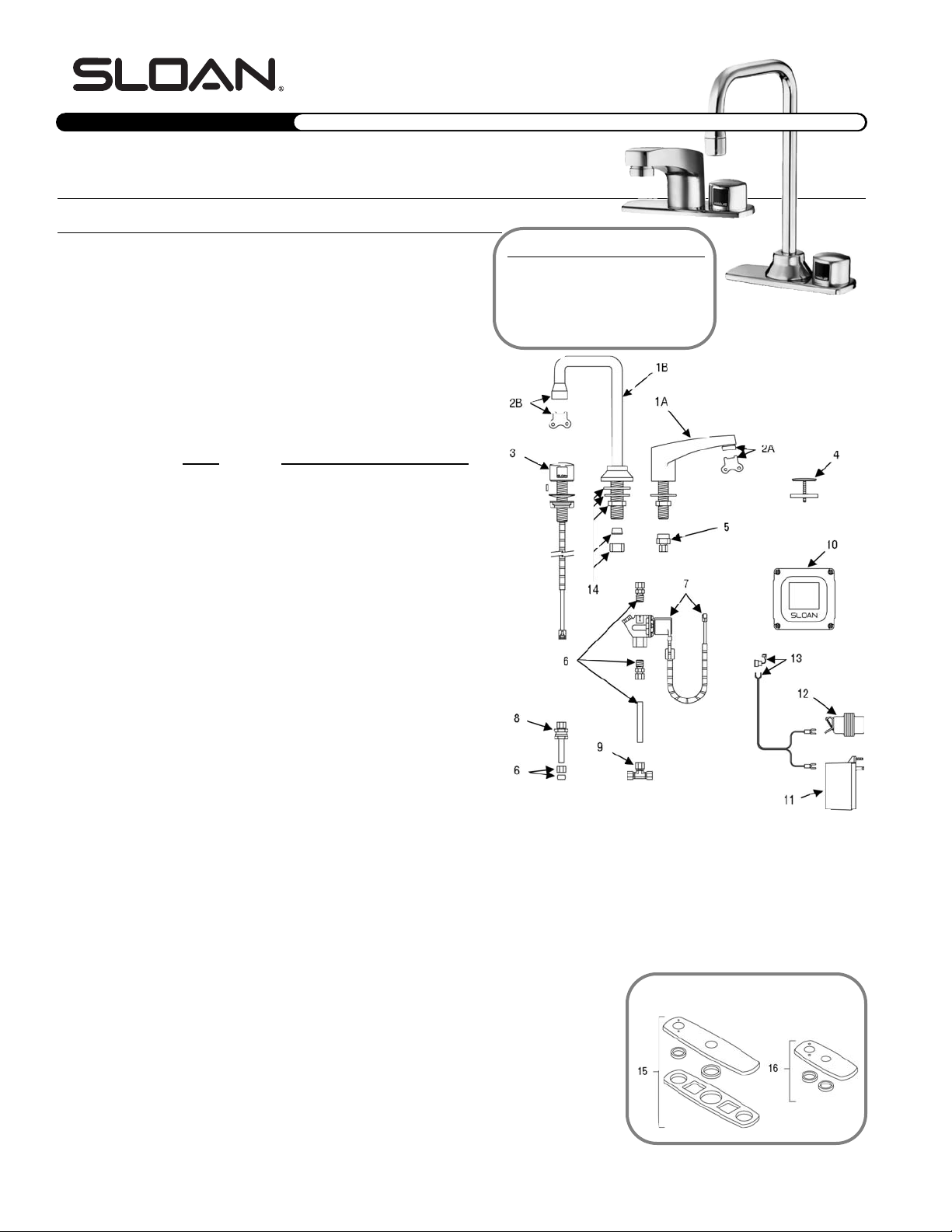
Parts List—ETF-660 and ETF-770 Faucets
Item Code Part Description
Number Number Number
1A 0305500 ETF-195-A Lavatory Faucet Assembly (ETF-660)
1B 0305536 ETF-261-A Deck-Mounted Gooseneck Faucet Assembly
(ETF-770)
2A 3365092 ETF-1023-A 0.5 gpm (1.9 Lpm) Spray Head with Key (male
thread)
3365093 ETF-1024-A 2.2 gpm (8.3 Lpm) Aerator Spray Head with
Key (male thread)
0305607 F-175-L 2.2 gpm (8.3 Lpm) Laminar Flow Spray Head
(male thread)
0306930 F-179 2.0 gpm (7.6 Lpm) Spray Head with Key
(male thread)
0305927 ETF-435 Replacement Key Only for ETF-1023-A Spray
Head and ETF-1024-A Aerator Spray Head (NOT
required for F-175-L Laminar Flow Spray Head)
2B 3365091 ETF-1021-A 0.5 gpm (1.9 Lpm) Spray Head with Key
(female thread)
discontinued ETF
-235 Spray Head, 2.0 gpm (7.6 Lpm), with Key
3365090 ETF-1022-A 2.2 gpm (8.3 Lpm) Aerator Spray Head with Key
(female thread)
0305612 ETF-237 2.2 gpm (8.3 Lpm) Laminar Flow Spray Head
(female thread)
0305927 ETF-435 Replacement Key Only for ETF-1021-A Spray
Head and ETF-1022-A Aerator Spray Head (NOT
required for ETF-237 Laminar Flow Spray Head)
3 0305946 EL-3500-A Microphone-style “On-Q” Sensor Assembly
includes “O” ring, 18” armored Cable,
Microphone Sensor Cap, Locking Pin,
Microphone Sensor Body, and Emitter/Detector
Shroud
— 0305527 EL-350-A Old-style Microphone Sensor Assembly includes
Washer, Beveled Washer, Basin Locknut,
Microphone Sensor Subassembly, and flat blade
Screwdriver
4 0365524 ETF-199 Cock Hole Cover
5 0365150 ETF-271 3/8” Tube Fitting Connector (female)
6 3365676 ETF-437-A Single Solenoid Supply Kit includes Supply Tube,
two (2) ETF-61 Compression Fittings,
Compression Nut, and Ferrule
7 0305849 ETF-370-A 24 VAC Solenoid Valve Assembly includes 18”
(153 mm) armored Cable and two (2) Terminal
Housings
8 3365001 ETF-470-A Back Check
9 0305728 ETF-259 3/8” Tee Compression Fitting
10 3306500 ETF-450-A Control Module Assembly includes splashproof Junction Box and Junction Box Mounting Kit
— 0305533 ETF-214-A Old-style Control Module Assembly includes Revision 3 Control Board, two (2) Anchor Screws, two (2) small and two (2) large
Phillips Screws, Junction Box Bottom, Junction Box Top, Junction Box Hole Plug, and Power Cord Hole Plug
11 0365534 ETF-233 120V/35VA Plug-In Transformer
12 0345370 EL-248-40 24V/40VA Box Mount Transformer
13 0365001 ETF-458-A Input Power Cable (Transformer to Control Module) includes Strain Relief and two (2) Terminal Crimp Connectors
14 0305768 EL-310-A Spout Mounting Kit (ETF-770 Only) Includes Rubber Washer, Steel Washer, Lock Nut, Rubber Cone Washer, and Coupling Nut
15 3365602 ETF-432-A Optional 8” (203 mm) Centerset Trim Plate Kit includes Seal, Washer Fender, Gasket, Finger Nut, Trim Plate Spacer, and Dual Hole
Trim Plate Assembly
16 3365468 ETF-313-A Optional 4” (102 mm) Centerset Trim Plate Kit includes Trim Plate Spacer and Dual Hole Trim Plate Assembly
— 3305577 ETF-1009-A Solenoid Valve Repair Kit includes Replacement Filter
FAUCET CABLE EXTENSION CORDS
— 0365042 ETF-1005-26
Faucet to Control Module Extension Cord; 26 inch (0.7 meter) Length
— 0365861 ETF-1005-36 Faucet to Control Module Extension Cord; 36 inch (0.9 meter) Length
— 0305862 ETF-1005-72 Faucet to Control Module Extension Cord; 72 inch (1.8 meter) Length
— 0305863 ETF-1005-108 Faucet to Control Module Extension Cord; 108 inch (2.7 meter) Length
— 0365838 ETF-1003-36 Solenoid to Control Module Extension Cord; 36 inch (0.9 meter) Length
— 0365053 ETF-1003-48 Solenoid to Control Module Extension Cord; 48 inch (1.2 meter) Length
— 0365839 ETF-1003-72 Solenoid to Control Module Extension Cord; 72 inch (1.8 meter) Length
— 0365840 ETF-1003-108 Solenoid to Control Module Extension Cord; 108 inch (2.7 meter) Length
Optional Trim Plates
SENSOR FAUCETS
PP aa rr tt ss GG uu ii dd ee
•24 VAC HARDWIRE FAUCETS
OPTIMA ETF-660 and ETF-770 Faucets
4
Old-Style Faucets
ETF-66 and ETF-77 faucets manufactured before 1996 used an EL-350-A
Microphone-Style Sensor with telephone
jack connector (0305527) and an
ETF-214-A Control Module (0305533).
Page 5
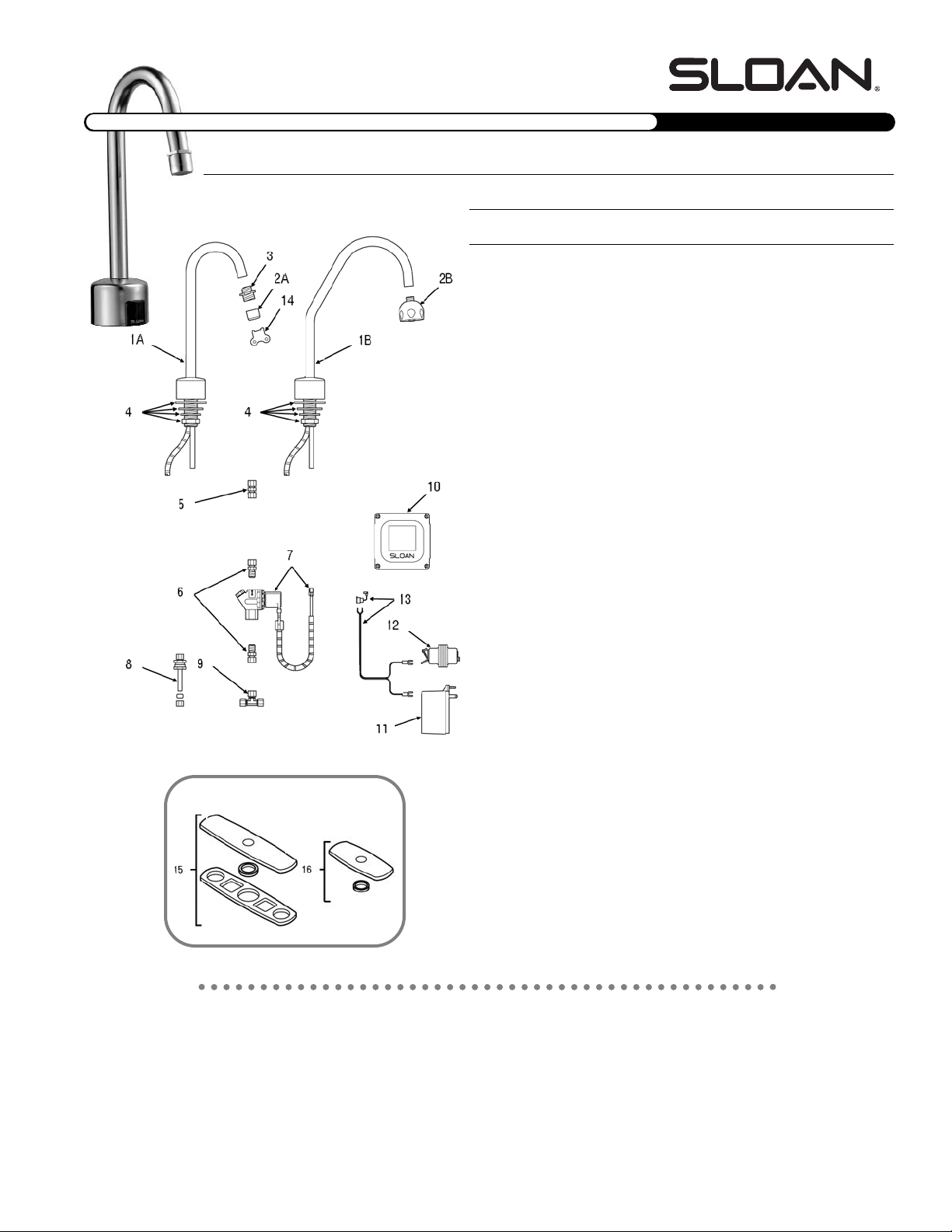
OPTIMA ETF-700 Faucet
SENSOR FAUCETS
Parts List—ETF-700 Faucet
Item Code Part Description
Number Number Number
1A 0365108 ETF-472-A Faucet and Sensor Assembly with Standard
Gooseneck Spout (ETF-700)
1B 0365109 ETF-473-A Faucet and Sensor Assembly with Surgical
Bend Gooseneck Spout (ETF-700-S)
— 0365028 ETF-476-A Sensor Module Only includes 18” (153 mm)
armored Cable, Shroud, and Housing for
Sensor Window (ETF-700 and ETF-700-S
Faucets)
2A 3365091 ETF-1021-A 0.5 gpm (1.9 Lpm) Spray Head with Key
(female thread)
3365090 ETF-1022-A 2.2 gpm (8.3 Lpm) Aerator Spray Head with
Key (female thread)
0305612 ETF-237 2.2 gpm (8.3 Lpm) Laminar Flow Spray
Head (female thread)
2B 0328134 AC-55-A Shower Spray Head Assembly, 2.2 gpm (8.3
Lpm)
3 0305784 ETF-178 Adapter for Spray Heads (not required for
AC-55-A Shower Spray Head)
4 0365110 ETF-503-A Spout Mounting Kit Includes Rubber Washer,
Flat Washer, Lockwasher, Mounting Nut, and
ETF-530 Union Compression Fitting
5 0365057 ETF-530 3/8” x 3/8” Union Compression Fitting
(female)
6 3365676 ETF-437-A Single Solenoid Supply Kit includes Supply
Tube, two (2) ETF-61 Compression Fittings,
Compression Nut, and Ferrule
7 0305849 ETF-370-A 24 VAC Solenoid Valve Assembly includes
18” (153 mm) armored Cable and two (2)
Terminal Housings
8 3365001 ETF-470-A Back Check
9 0305728 ETF-259 3/8” Tee Compression Fitting
10 3306500 ETF-450-A Control Module Assembly includes splash-
proof Junction Box and Junction Box
Mounting Kit
11 0365534 ETF-233 120V/35VA Plug-In Transformer
12 0345370 EL-248-40 24V/40VA Box Mount Transformer
13 0365001 ETF-458-A Input Power Cable (Transformer to Control
Module) includes Strain Relief and two (2)
Terminal Crimp Connectors
14 0305927 ETF-435 Replacement Key Only for
ETF-1021-A Spray
Head and ETF-1022-A Aerator Spray Head
(NOT required for ETF-237 Laminar Flow
Spray Head)
15 3365601 ETF-431-A Optional 8” (203 mm) Centerset Trim Plate
Kit includes Seal, two (2) Washer Fenders,
two (2) Gaskets, two (2) Finger Nuts, Trim
Plate Spacer, and Single Hole Trim Plate
Assembly
16 3365468 ETF-312-A Optional 4” (102 mm) Centerset Trim Plate
Kit includes Trim Plate Spacer and Single
Hole Trim Plate Assembly
— 3305577 ETF-1009-A Solenoid Valve Repair Kit includes
Replacement Filter
Optional Trim Plates
FAUCET CABLE EXTENSION CORDS
— 0365042 ETF-1005-26 Faucet to Control Module Extension Cord; 26 inch (0.7 meter) Length
— 0365861 ETF-1005-36 Faucet to Control Module Extension Cord; 36 inch (0.9 meter) Length
— 0305862 ETF-1005-72 Faucet to Control Module Extension Cord; 72 inch (1.8 meter) Length
— 0305863 ETF-1005-108 Faucet to Control Module Extension Cord; 108 inch (2.7 meter) Length
— 0365838 ETF-1003-36 Solenoid to Control Module Extension Cord; 36 inch (0.9 meter) Length
— 0365053 ETF-1003-48 Solenoid to Control Module Extension Cord; 48 inch (1.2 meter) Length
— 0365839 ETF-1003-72 Solenoid to Control Module Extension Cord; 72 inch (1.8 meter) Length
— 0365840 ETF-1003-108 Solenoid to Control Module Extension Cord; 108 inch (2.7 meter) Length
5
PP aa rr tt ss GG uu ii dd ee
24 VAC HARDWIRE FAUCETS•
Page 6

SENSOR FAUCETS
PP aa rr tt ss GG uu ii dd ee
•24 VAC HARDWIRE FAUCETS
1. PROBLEM: No water is delivered when faucet is activated.
INDICATOR: If no LED lights illuminate:
CAUSE: No electricity is being supplied to faucet.
SOLUTION: Ensure that the main power is turned “ON”. Check all
transformer, sensor, solenoid and cable connections.
Make sure that transformer is supplying 24 VAC (Volts
AC). If no voltage is detected, replace transformer.
CAUSE: There is an electrical system malfunction.
SOLUTION: Reset electrical system. Unplug Sensor connection.
Disconnect power to circuit for ten (10) seconds.
Reconnect.
INDICATOR: If the GREEN LED illuminates when power is reconnected:
CAUSE: There is a short in the Sensor.
SOLUTION: Replace Sensor. Refer to individual faucet parts diagram
for appropriate Sensor Assembly.
Note: GREEN LED may illuminate immediately after Sensor disconnection.
CAUSE: There is a short in the Solenoid or Solenoid cable.
SOLUTION: Replace ETF-370-A Solenoid.
INDICATOR: If the GREEN LED does NOT illuminate when power is reconnected:
CAUSE: There is an electrical system malfunction.
SOLUTION: Reset electrical system. Unplug Sensor connection.
Disconnect power to circuit for ten (10) seconds.
Reconnect.
CAUSE: The Control Module circuit is “dead”.
SOLUTION: Replace ETF-450-A Control Module.
INDICATOR: If GREEN LED illuminates AND changes to RED when hands are in
the Sensor’s detection zone AND the RED Solenoid LED illuminates:
CAUSE: Water supply stop(s) may be partially closed.
SOLUTION: Open stop(s) if closed.
CAUSE: Debris is clogging Solenoid Filter.
SOLUTION: Shut off water supply. Remove, clean and reinstall
Solenoid Filter.
INDICATOR: If GREEN LED illuminates AND changes to RED when hands are
placed in the Sensor’s detection zone AND the RED Solenoid LED
flickers with a vibrating/clicking noise heard inside the module:
Note: Applies only to REVISION 2 MODULES.
CAUSE: There is a direct short in the Solenoid or Solenoid cable.
SOLUTION: Replace with ETF-370-A solenoid
INDICATOR: If green/red LED illuminates AND changes to RED when hands are
NOT located in the Sensor’s detection zone BUT the red Solenoid
LED (in upper left corner of circuit) does NOT illuminate:
CAUSE: Sensor range is set too long and is detecting the sink.
SOLUTION: Reduce Sensor detection range.
CAUSE: Sensor is faulty.
SOLUTION: Replace Sensor. Refer to individual faucet parts diagram
for appropriate Sensor Assembly.
INDICATOR: If green LED illuminates BUT does NOT change to red when
hands are placed in the Sensor’s detection zone:
CAUSE: Sensor range is set too short.
SOLUTION: Increase Sensor detection range.
CAUSE: Sensor is faulty.
SOLUTION: Replace Sensor. Refer to individual faucet parts diagram
for appropriate Sensor Assembly.
2. PROBLEM: Sensing Range is too short.
CAUSE: Extended Range Sensitivity is required.
SOLUTION: Dip Switch number 4 should be in the “DOWN”
(Extended Range Sensitivity) position. Increase range by
adjusting range potentiometer clockwise (yellow phillips
screw in blue base).
CAUSE: Faucet has Surgical Bend Gooseneck Spout.
SOLUTION: For Long Range use (recommended for Surgical Bend
Gooseneck Spout faucet models), remove Range Jumper
from upper right hand corner of circuit board. Adjust
range potentiometer.
Note: Applies only to REVISION 2 MODULES.
3. PROBLEM: Faucet activates by itself (false triggers).
CAUSE: Sensor range is set too long.
SOLUTION: Decrease range by adjusting range potentiometer
counterclockwise. If necessary, flip Dip Switch number 4
into the “UP” (Reduced Range Sensitivity) position.
Check surroundings for factors that contribute to Sensor
range detection problems (bright lights, highly reflective
surfaces, sunlight, etc.).
4. PROBLEM: Faucet delivers very low flow or just a dribble.
CAUSE: Water Supply Stop(s) may be partially closed.
SOLUTION: Open stop(s).
CAUSE: Debris is clogging Solenoid Filter.
SOLUTION: Shut off water. Remove, clean, and reinstall Solenoid
Filter.
CAUSE: Solenoid is worn or faulty.
SOLUTION: Rebuild with ETF-1009-A Solenoid Repair Kit or replace
ETF-370-A Solenoid.
CAUSE: Debris is clogging faucet Aerator or Spray Head.
SOLUTION: Shut off water. Use Key if required to remove. Then clean
and reinstall Aerator or Spray Head.
5. PROBLEM: Faucet does not stop delivering water or continues to
drip after user is no longer detected (even after power
to the Module has been disconnected).
CAUSE: Solenoid Valve is installed backward.
SOLUTION: Disconnect Solenoid. Reconnect Solenoid with water
flow towards the faucet (see arrow on Solenoid).
CAUSE: Debris is clogging Solenoid.
SOLUTION: Remove and clean Solenoid operator. If necessary,
rebuild with ETF-1009-A Repair Kit.
CAUSE: Seat in Solenoid valve body is damaged or pitted.
SOLUTION: Replace with ETF-370-A solenoid.
The information contained in this document is subject to change without notice.
Troubleshooting Guide for ETF-80, ETF-500, ETF-600, ETF-610, ETF-660, ETF-700, and ETF-770 Faucets
NOTE: Revision 2 ETF-450-A Control Modules (manufactured after April 1999) have built-in reset fuses to protect the circuitry if a sensor or solenoid fails or shorts. In
earlier models, a sensor or solenoid short or failure could also result in an ETF-450-A Control Module failure.
SLOAN VALVE COMPANY • 10500 SEYMOUR AVENUE • FRANKLIN PARK, IL 60131
Phone: 1-800-9-VALVE-9 1-847-671-4300 • Fax: 1-800-447-8329 1-847-671-4380 • http://www.sloanvalve.com
Copyright © 2004 Sloan Valve Company Printed in U.S.A. Made in U.S.A. OPTIMA FAU M.G. — Rev. 0a (03/04) Code No 0816519
NOTE: REMOVE COVER FROM ETF-450-A CONTROL MODULE TO CHECK DIAGNOSTIC LIGHTS.
Care and Cleaning Instructions:
DO NOT USE abrasive or chemical cleaners to clean Faucets that may dull the luster and
attack the chrome or special decorative finishes. Use ONLY soap and water, then wipe dry with a clean towel or cloth. When cleaning the
bathroom tile, protect the Faucet from any splattering of cleaner. Acids and cleaning fluids can discolor or remove chrome plating.
Need Help? Call 1-888-SLOAN-14
(1-888-756-2614)
.
LIMITED WARRANTY
Sloan Valve Company warrants its Faucet Products to be made of first class materials, free from defects of material or workmanship under normal use and to perform the service for which they are intended in a thoroughly reliable and efficient
manner when properly installed and serviced, for a period of three years (one year for special finishes) from date of purchase. During this period, Sloan Valve Company will, at its option, repair or replace any part or par ts which prove to be
thus defective if returned to Sloan Valve Company, at customer’s cost, and this shall be the sole remedy available under this warranty. No claims will be allowed for labor, transportation or other incidental costs. This warranty extends only to
persons or organizations who purchase Sloan Valve Company’s products directly from Sloan Valve Company for purpose of resale.
THERE ARE NO WARRANTIES WHICH EXTEND BEYOND THE DESCRIPTION ON THE FACE HEREOF. IN NO EVENT IS SLOAN VALVE COMPANY RESPONSIBLE FOR ANY CONSEQUENTIAL DAMAGES OF ANY MEASURE WHATSOEVER.
 Loading...