

Page 1
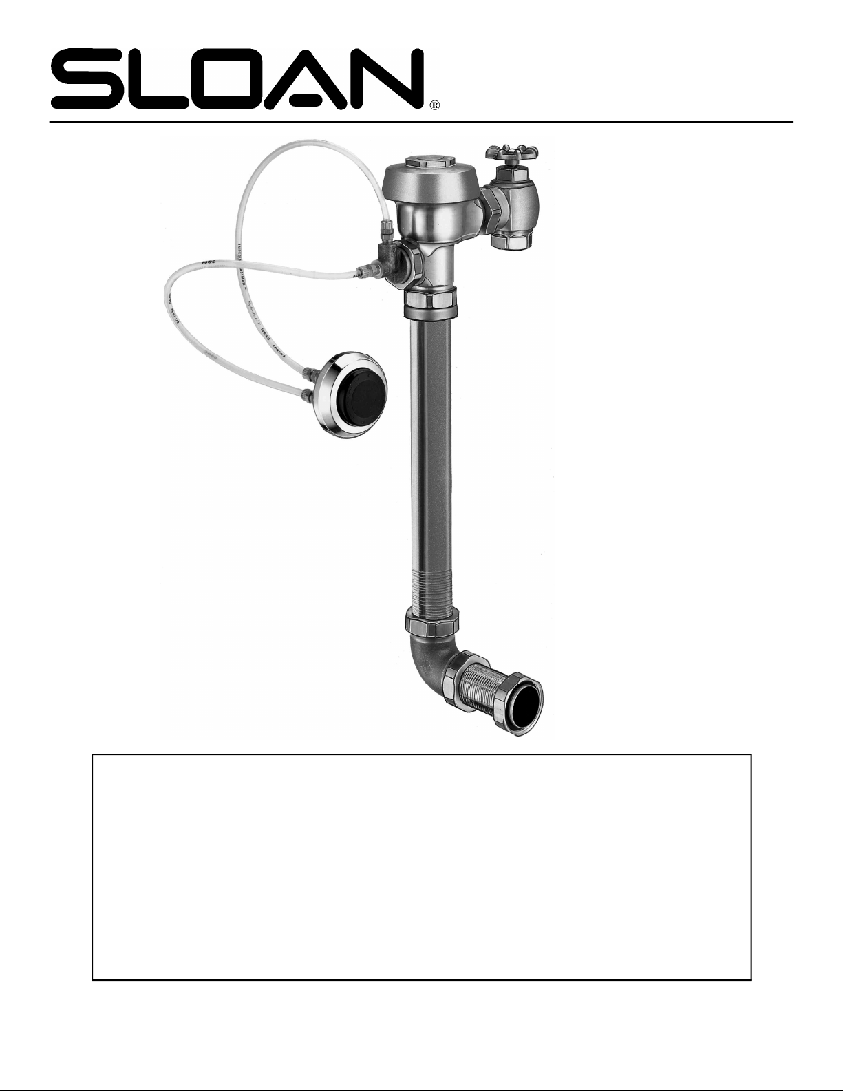
SERIES 900™ HYDRAULIC FLUSHING SYSTEM
REPAIR & MAINTENANCE GUIDE
LIMITED WARRANTY
Sloan Valve Company warrants its Hydraulic Flushometer to be made of first class materials, free from defects of material or workmanship under normal use and to perform the service for which they are intended in a thoroughly reliable and efficient manner when
properly installed and serviced for a period of 3 years from date of purchase. During this period, Sloan Valve Company will, at its option,
repair or replace any part or part which prove to be thus defective if returned to Sloan Valve Company, at customer’s cost, and this
shall be the sole remedy available under this warranty. No claims will be allowed for labor, transportation or other incidental costs. This
warranty extends only to those persons or organizations who purchase Sloan Valve Company’s products directly from Sloan Valve
Company for purpose of resale.
THERE ARE NO WARRANTIES WHICH EXTEND BEYOND THE DESCRIPTION ON THE FACE HEREOF. IN NO EVENT IS
SLOAN VALVE COMPANY RESPONSIBLE FOR ANY CONSEQUENTIAL DAMAGES OF ANY MEASURE WHATSOEVER.
SLOAN VALVE COMPANY • 10500 SEYMOUR AVENUE • FRANKLIN PARK, IL 60131
Ph: 800/9-VALVE-9 847/671-4300 • Fax: 800/447-8329 847/671-4380 • http://www.sloanvalve.com
©Sloan Valve Company 1/99 Printed in U.S.A. Made in U.S.A. Code No. 0816319 Rev 1
Page 2

Series 900
®
Hydraulic Flushing System
Maintenance Guide
ACTUATOR
(FLUSHOMETER)
CONNECTING
TUBES
PUSH BUTTON
ACTUATOR
(SPECIFY TYPE)
COVER
CONTROL STOP
STOP COUPLING
TAILPIECE
BODY
COUPLING
FLUSH CONNECTION
(VACUUM BREAKER)
ELBOW FLUSH
CONNECTION,
COUPLINGS
& OUTLET TUBE
PARTS LIST
Item No.Code No. Part No. Description
1 0301173 A-72 RB Cover
2 0301168 A-71 Inside Cover
3a 5301058 A-19-AC Relief Valve, Closet (white) (1 required; 12 per pkg.)
3b 5301059 A-19-AU Relief Valve, Urinal (black) (1 required; 12 per pkg.)
3c 5301211 A-19-ALC Relief Valve, LC Closet/Urinal (green) (1 required; 12 per pkg.)
3d 5301143 A-19-AL Relief Valve, 9 L Closet (blue) (1 required; 12 per pkg.)
4 5301111 A-15-A Disc - for all Inside Parts Kits (1 required; 12 per pkg.)
5 5301188 A-156-A Diaphragm - for all Inside Parts Kits (1 required; 12 per pkg.)
6a 5301236 A-163-A Guide Assembly for Closet (4.5 gpf/17.0 Lpf)
6b 5301032 A-152-A Guide Assembly for Closet (3.5 gpf/13.2 Lpf) (1 required; 12 per pkg.)
6c 5301031 A-151-A Guide Assembly for LC Closet (1.6 gpf/6.0 Lpf) (1 required; 12 per pkg.)
6d 5301155 A-155-A Guide Assembly for LC Urinal (1.0 gpf/3.8 Lpf) (1 required; 12 per pkg.)
6e 5301157 A-157-A Guide Assembly for Urinal (0.5 gpf/1.9 Lpf) (1 required; 12 per pkg.)
7 SEE THE INSIDE PARTS KIT CHART
8 3323182 V-651-A Vacuum Breaker Repair Kit
9 0308690 H-550 RB Tailpiece Coupling
10 0308802 H-551-A RB Adjustable Tailpiece, 2-1/16” (52 mm)
11 0388010 H-730-A RB Wheel Handle Bak-Chek® Control Stop
12a 3308855 H-541-A 1” Wheel Handle Repair Kit for H-730-A Control Stop
12b 3308858 H-543-A 3/4” Wheel Handle Repair Kit for H-730-A Control Stop
13 0308919 H-558-A Wheel Handle
14a 0208079 H-561 1” RB Bonnet
14b 0208083 H-623 3/4” RB Bonnet
15 ——— V-500-A Vacuum Breaker Flush Connection (specify size)
16 0306619 F-2-AA 1-1/2” (38 mm) RB Couplings (2 each), Friction Rings (2 each),
17 0206146 F-21 RB Elbow
18 0306087 F-2-A 1” (25 mm) RB Coupling, Friction Ring, and Rubber Gasket
19 ——— F-100 RB Flared End Flush Connection (specify length)
20 ——— F-15-A 3/4” (19 mm) RB Elbow Flush Connection with Coupling and Rubber Gasket
21 0306054 F-2-A 3/4” (19 mm) RB Coupling, Friction Ring, and Rubber Gasket
22 0318024 HY-25 RB Valve Actuator Housing only
23 0318023 HY-24 Tube Fitting (2 required)
24 0318033 HY-35 Tube Fitting Nut (2 required)
25 0318093 HY-30 1/4” (6 mm) x 48” (1219 mm) Connecting Tubes (2 required)
26 0301083 A-6 RB Handle Coupling Nut
27 0337086 DO-22 “O” Ring
28 3318005 HY-109-A Actuator Housing Assembly (includes items 22, 23, 24, 26, and 27)
29 3318001 HY-83-A Actuator Cartridge Assembly (Replacement Kit, includes item 27)
or Urinal (1.5 gpf/5.7 Lpf) (1 required; 12 per pkg.)
and Rubber Gaskets (2 each)
(specify length)
Each item has been identified by a Part Number and a
corresponding Code Number. To expedite your replacement requirements, order by Code Number.
ABBREVIATIONS:
Assem. = Assembly
CP = Chrome Plated
RB = Rough Brass
gpf = gallons per flush
Lpf = Liters per flush
LC = Low Consumption
WH = Wheel Handle
Page 3

ROYAL FLUSHOMETER INSIDE PARTS KITS (item #7 from previous page)
7. INSIDE PARTS KITS
HY-32-A (0318031)
ACTUATOR CARTRIDGE ASSEMBLY
A-36-A
3301036
4.5 gpf/17.0 Lpf
CLOSET
A-37-A
3301037
1.5 gpf/5.7 Lpf
URINAL
A-38-A
3301038
3.5 gpf/13.2 Lpf
CLOSET
A-41-A
3301041
1.6 gpf/6.0 Lpf
CLOSET
PUSH BUTTON ACTUATOR VARIATIONS
HY-49-A (0318049)
METAL PARTITION PUSH BUTTON
1 3318007 HY-1000-A Push Button Kit - includes Push
2 0318004 HY-3 Spring
3 3318010 HY-1003-A Mounting Flange Kit - includes
4 0318123 HY-71-A Actuator Assembly
5 0218046 HY-46 Mounting Flange
NOTE: Includes HY-32-A Cartridge (shown above)
Button, Flange, Spring & Set Screw
Mounting Flange, Mounting Nut,
Screws (2) & Tinnerman Nuts (2)
A-42-A
3301044
1.0 gpf/3.8 Lpf
URINAL
A-43-A
3301081
0.5 gpf/1.9 Lpf
URINAL
A-44-A
3301024
2.4 gpf/9.0 Lpf
CLOSET
HY-72-A (0318072)
SIDE WALL PUSH BUTTON
1 3318007 HY-1000-A Push Button Kit - includes Push
2 0318004 HY-3 Spring
3 3318008 HY-1001-A Mounting Flange Kit - includes
4 0318123 HY-71-A Actuator Assembly
5 0218043 HY-40 Plate
6 0305173 EL-173 Screws (4)
7 0318073 HY-73 Extension Adapter
8 0318074 HY-74 Extension Stem
NOTE: Includes HY-32-A Cartridge (shown above)
Button, Flange, Spring & Set Screw
Mounting Flange, Mounting Nut,
Screws (2), Nuts (2) & Washers (2)
For use with HY-50-A and HY-71-A Actuator Assemblies
(see Actuators listed below)
HY-108-A (0318119)
PENAL WARE METAL PUSH BUTTON
1 0318116 HY-91 Flange
2 0318111 HY-94 Mounting Washer
3 0318112 HY-93 Mounting Nut
4 0318115 HY-86-A Push Button Assembly
5 0305134 EL-109 Spring
6 0318078 HY-50-A Actuator Assembly
NOTE: Includes HY-32-A Cartridge (shown above)
HY-100-A (0318117)
FIXTURE WALL METAL PUSH BUTTON
1 0318117 HY-100-A Fixture Wall Metal Button Assembly
2 3318006 HY-111-A Metal Button Kit
3 0305134 EL-109 Spring
4 0318078 HY-50-A Actuator Assembly
5 0318033 HY-35 Tube Fitting Nut (2 required)
6 0318028 HY-29 Threaded Rod
7 0318109 HY-105 Spacer
8 3318009 HY-1002-A Mounting Strap Kit
HY-33-A (0318001)
FIXTURE WALL PUSH BUTTON
1 0318001 HY-33-A Fixture Wall Push Button Assembly
2 3318007 HY-1000-A Push Button Kit
3 0318004 HY-3 Spring
4 3318008 HY-1001-A Mounting Flange Kit
5 0318078 HY-50-A Actuator Assembly
6 0318033 HY-35 Tube Fitting Nut (2 required)
7 0318028 HY-29 Threaded Rod
8 0318109 HY-105 Spacer
9 3318009 HY-1002-A Mounting Strap Kit
Page 4

TROUBLESHOOTING AND MAINTAINING THE SLOAN
SERIES 900™ HYDRAULIC FLUSHING SYSTEM
Push Button Actuator Assembly
I. Leakage occurs at the Push Button.
Cause: Damaged or worn Seals or lime build-up in the Actuator
Cartridge.
Solution:Replace with new HY-32-A Cartridge.
II. Flushometer does not flush and a small amount of leakage is visible
on the fixture.
Cause: Foreign material is lodged in the Cartridge.
Solution:Remove and inspect Cartridge for foreign material. Clean
Cartridge under running water.
Cause: Damaged or worn Seals or lime build-up in the Actuator
Cartridge.
Solution:Replace with new HY-32-A Cartridge.
Cause: Plastic Tubing installed incorrectly.
Solution:Install Plastic Tubing correctly.
Actuator Cartridge Removal at Push Button
Plastic Push Button:
1. Loosen the Set Screw in the Button Flange and remove the Button,
Flange and Spring from the Actuator Body.
2. Unscrew the Cartridge from the Actuator Body.
NOTE: An automatic Check Valve in the Actuator Body allows
removal of the Cartridge without turning off the water supply.
Metal Push Button:
1. Remove the Button or Actuator Assembly from the wall or the
fixture
2. Disassemble the Flange or Button Assembly from the Actuator
Body.
3. Unscrew the Cartridge from the Actuator Body.
NOTE: The Metal Push Button was designed to be vandal resistant
and must be removed from the wall before servicing.
Flushometer Actuator Assembly
I. The Flushometer does not flush or flushes only once and will not flush
a second time when the Button is pushed.
Cause: The Plunger is lodged in the Actuator Cartridge or the Plunger
bypass hole is clogged.
Solution:Remove the Actuator Housing and Cartridge from the
Flushometer. Clean under running water. If Cartridge Parts are
worn, deteriorated, or limed up and the problem persists after
cleaning, replace with new HY-83-A Cartridge (item 29).
Cause: Plastic Tubing installed incorrectly.
Solution:Install Plastic Tubing correctly.
Actuator Removal from the Flushometer
1. Turn off water at the Control Stop (item 11).
2. Unscrew the Housing Coupling Nut (item 26) from the Flushometer.
3. Remove the Valve Actuator Housing (item 22) from the Flushometer. The
Tubing (item 25) can be left intact.
4. Remove the Actuator Cartridge Assembly (item 29) from the
Flushometer Body. Care should be taken upon removal so that the
Actuator does not abruptly separate due to spring compression within. If
the Actuator Cartridge is lodged in the Body Cavity, grip the exposed
portion gently with a pair of channel-lock pliers and rotate back and
forth to loosen the “O” Ring seal.
5. Separate the Actuator Housing to reveal the Spring and Plunger. Inspect
for wear and, if necessary, replace with new Actuator Cartridge
Assembly (item 29).
Flushometer Service
I. The Flushometer does not function.
Cause: The Control Stop or main water supply valve is closed.
Solution:Open Control Stop or main water supply valve.
II. The volume of water is insufficient to adequately siphon the fixture.
Cause: The Control Stop is not open wide enough.
Solution:Open Control Stop for desired delivery of water.
Cause: Urinal Inside Parts installed incorrectly in a Closet Flushometer.
Solution:Replace with correct Closet Inside Parts kit (see item 7).
Cause: Inadequate volume or pressure at the water supply valve.
Solution:If no gauges are available to properly measure the supply
pressure or the volume of water at the Flushometer, completely
remove the entire Diaphragm Assembly (item 7). Open the
Control Stop and let water pass through the empty Flushometer
Body. Make sure that the water supply is adequate to siphon the
fixture. If this does not provide a satisfactory siphon, steps
should be taken to increase the water supply pressure and/or
volume.
III. The Flushometer closes off immediately.
Cause: The Diaphragm is ruptured or damaged.
Solution:Install new Inside Parts Kit (see item 7).
Cause: The bypass hole is enlarged from corrosion or damage.
Solution:Install new Inside Parts Kit (see item 7).
IV. The length of the flush is too short.
Cause: The Diaphragm (item 5) and the Guide Assembly (item 6A, B,
C, D or E) are not properly tightened.
Solution:Screw Diaphragm and Guide Assembly together and tighten by
hand (see diagram for item 7).
Cause: The bypass hole is enlarged from corrosion or damage.
Solution:Install new Inside Parts Kit (see item 7).
Cause: Urinal Inside Parts installed incorrectly in a Closet Flushometer.
Solution:Replace with correct Closet Inside Parts kit (see item 7).
V. The length of the flush is too long or continuous.
Cause: The Relief Valve of the Inside Parts Assembly (item 3A, B, C
or D) is not seating properly or the bypass hole is clogged with
foreign material or by a gelatinous film caused by “overtreated”
water.
Solution:Disassemble the working parts and wash under running water.
NOTE: THE SIZE OF THE DIAPHRAGM BYPASS ORIFICE IS OF UTMOST
IMPORTANCE. DO NOT ENLARGE OR DAMAGE THIS HOLE. DO NOT USE A
PIN OR OTHER SMALL OBJECT TO REMOVE DIRT FROM THIS ORIFICE.
Cause: Line pressure has dropped and is no longer sufficient enough to
force the Relief Valve to seat properly.
Solution:Close Control Stop until adequate pressure has been restored to
the line, then reopen Control Stop.
VI. Water splashes out from the fixture.
Cause: The water supply volume is more than required.
Solution:Throttle down Control Stop to reduce volume.
Cause: Lime has accumulated on the vortex or spreader hole of the
fixture.
Solution:Remove lime accumulation.
If further assistance is required, please contact the Sloan Valve Company
Installation Engineering Department at 847-671-4300.
The information contained in this document is subject to change without notice.
SLOAN VALVE COMPANY • 10500 SEYMOUR AVENUE • FRANKLIN PARK, IL 60131
Ph: 800/9-VALVE-9 847/671-4300 • Fax: 800/447-8329 847/671-4380 • http://www.sloanvalve.com
©Sloan Valve Company 1/99 Printed in U.S.A. Made in U.S.A. Code No. 0816319 Rev 1
 Loading...