

Page 1
5314050 CN-1010-A
CROWN/NAVAL VALVE WASHER SET - 6 per pkg. includes:
5, 6, 7, C, H, J, Cap Screw Gasket & Regulating Screw Packing
5314094 CN-1004-A
PISTON REBUILD KIT-CLOSET & URINAL - 6 per pkg. includes:
5, A, B, C, D, H, J, Cap Screw Gasket & Regulating Screw Packing
5314184 CN-1006-A
PISTON REBUILD KIT-SHOWER - 6 per pkg. includes:
5, A, B, C, D, H, J, Cap Screw Gasket & Regulating Screw Packing
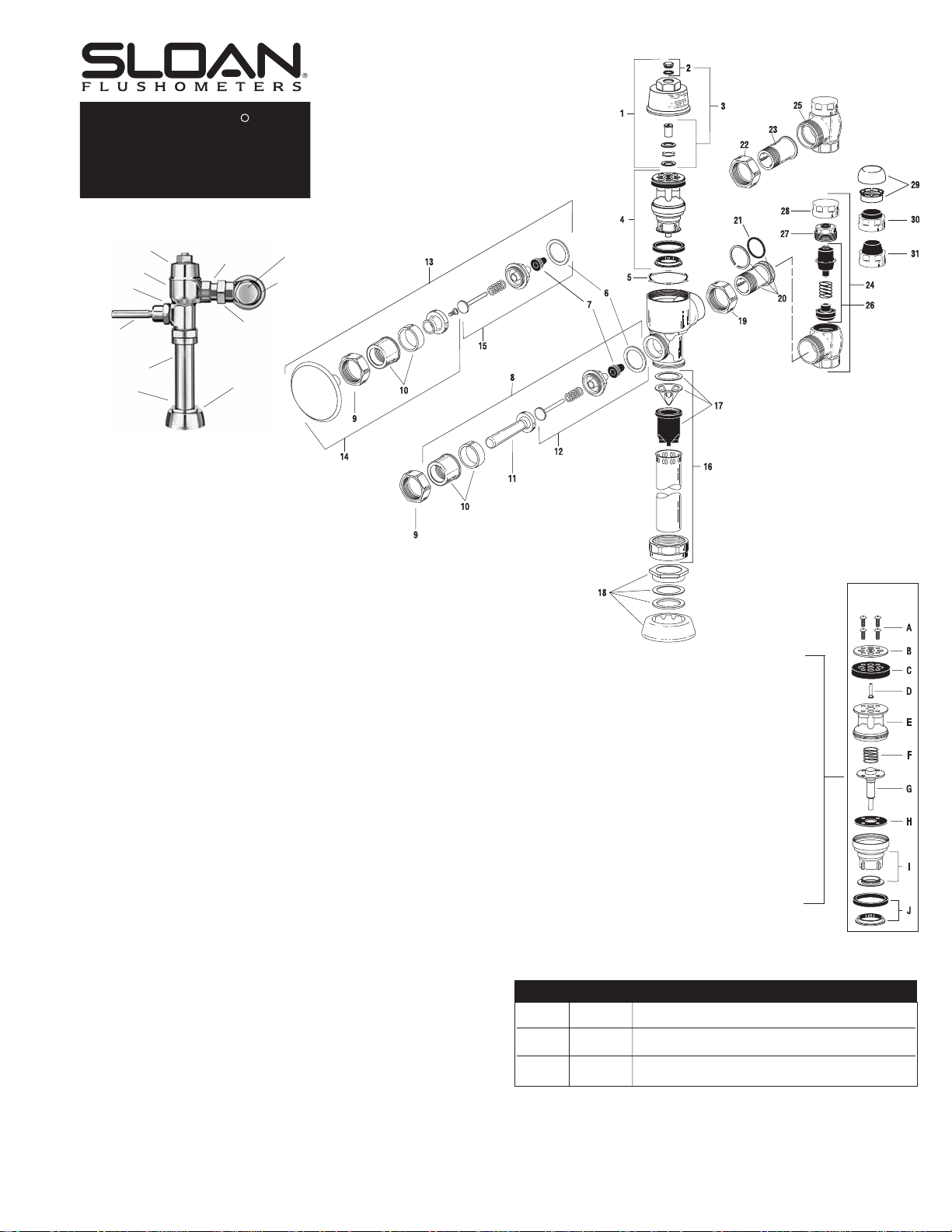
NAVAL PISTON COMPONENTS
A 0314200
CN-17 Top Plate Screws - 24 per pkg.
B 0314082
CN-15 Top Plate
0314179
CN-15-A Top Plate - Shower Valve only
C 5314188
CN-68-A Single Lip Cup - 12 per pkg.
D 0314204
CN-57 Xpelor
E 0314228
CN-160 Piston Body
F 5328019
SH-406 Spring - 12 per pkg.
G 0314078
CN-18-A Relief Valve
H 5314226
CN-120 Relief Valve Seat - 12 per pkg.
I 0314240
CN-123-AC Guide Assembly - Closet
0314242
CN-123-AU Guide Assembly - Urinal
0314189
CN-66-A Guide Assembly - Shower
J 0314234
CN-21-A Main Seat
0314223
CN-121-A Main Seat - Shower Valve only
NOTE: Naval Pistons can be used to replace Pistons in older Crown and Star
Flushometers
REPAIR KITS
The information contained in this document is subject to change without notice.
COVER
BODY
HANDLE
COUPLING
HANDLE
FLUSH CONNECTION
(VACUUM BREAKER)
SPUD COUPLING
SPUD
FLANGE
STOP COUPLING
SUPPLY
FLANGE
CONTROL STOP
TAILPIECE
PARTS LIST
1. 0314193
CN-74-A Cover Assembly CP
2. 5314010
CN-1007-A Cap Screw Repair Kit - 6 per pkg.
3. 3314015
CN-1008-A Regulating Screw Repair Kit
4. 0314016
CN-1002-A Piston with Main Seat - Closet
0314017
CN-1003-A Piston with Main Seat - Urinal
0314191
CN-1009-A Piston with Main Seat - Shower
5. 5314243
CN-76 Cover Gasket - 12 per pkg.
6. 5301139
A-31 Handle Gasket - 48 per pkg.
7. 5302297
B-39 Handle Seal - 12 per pkg.
8. 0302390
B-73-A Triple Seal Handicap Handle Assembly (ADA Compliant)
9. 0301082
A-6 Handle Coupling CP
10. 0302109
B-7-A Socket Assembly CP
11. 0302389
B-74-A Handicap Handle Grip CP (ADA Compliant)
12. 3302306
B-51-A Triple Seal Handle Repair Kit - 1 per pkg.
13. 0303351
C-42-A 3'' Push Button Assembly CP
14. 3303347
C-1000-A 3'' Push Button Replacement Kit
15. 3303396
C-64-A 3'' Push Button Repair Kit
16. 5323005
V-500-A ¾'' x 9'' Vacuum Breaker
5323006
V-500-A 1¼'' x 9'' Vacuum Breaker
5323007
V-500-A 1½'' x 9'' Vacuum Breaker
17. 3323192
V-551-A Vacuum Breaker Repair Kit
18. 0306125
F-5-A ¾'' Spud Coupling CP
0306140
F-5-A 1¼'' Spud Coupling CP
0306146
F-5-A 1½'' Spud Coupling CP
19. 0308676
H-550 Stop Coupling CP
20. 0314289
NH-551-A Adjustable Tailpiece 2-1/16'' CP
21. 5308696
H-553 O-ring - 24 per pkg.
22. 0308063
H-6 Ground Joint Stop Coupling CP
23. 0314028
NH-5 Ground Joint Tailpiece 1-5/8''
24. 0388022
H-710-A 1'' Adjustable Tailpiece SD Bak-Chek Control Stop CP
0388025
H-710-A ¾'' Adjustable Tailpiece SD Bak-Chek Control Stop CP
25. 0388024
H-710-AG 1'' Ground Joint Screwdriver Bak-Chek Control Stop CP
0388026
H-710-AG ¾'' Ground Joint Screwdriver Bak-Chek Control Stop CP
26. 3308853
H-541-A Control Stop Repair Kit †
3308856
H-543-A Control Stop Repair Kit ‡
27. 0308612
H-622 Bonnet CP †
0308843
H-577 Bonnet CP ‡
28.0308840
H-573 Control Stop Cap CP †
0308848
H-582 Control Stop Cap CP ‡
29. 3308791
H-1010-A Vandal Resistant Stop Cap Assembly †
3308790
H-1009-A Vandal Resistant Stop Cap Assembly ‡
30. 3308866
H-574 Control Stop Cap with Bumper †
31. 3308867
H-576 Control Stop Cap with Extended Bumper †
† For use with H-700-A 1'' & ¾'' and H-600-A 1'' Screwdriver Bak-Chek®Control Stops.
‡ For use with H-600-A ¾'' Screwdriver Bak-Chek
®
Control Stops.
No. 4 PISTON
(Exploded View)
Also for use with CROWN®and STAR®Flushometers
SLOAN VALVE COMPANY • 10500 SEYMOUR AVENUE • FRANKLIN PARK, IL 60131
Phone: 1-800-9-VALVE-9 or 1-847-671-4300 • Fax: 1-800-447-8329 or 1-847-671-4380 • http://www.sloanvalve.com
Copyright © 2003 Sloan Valve Company Printed in the U.S.A. Made in the U.S.A. NAVAL M.G. — Rev. 1b (05/03) Code No. 0816187
R
NAVAL
Flushometer
Maintenance Guide
Page 2

Troubleshooting and Maintaining the Sloan Naval® Flushometer
The Repair Kits and Parts listed are designed to service most variations of Sloan Piston
Type (Naval, Crown, Crown/Naval and Star) Exposed and Concealed Flushometers.
Each item has been identified by a Part Number and a corresponding Code Number. To
expedite your replacement requirements, order by Code Number.
NOTE: In all Piston variations the SH-406 Spring has replaced the “U” Bar. In all Piston
variations the CN-68-A Single Lip Cup has replaced the S-14-A Double Lip Cup. When
rebuilding a Piston, install the CN-68-A Single Lip Cup with the cup facing down.
Consult your Sloan Representative or the factory for assistance in crossing over older
part and kit numbers to current Crown/Naval numbers.
1. PROBLEM: Valve does not function.
CAUSE: (a.) Control Stop or Main Valve Closed.
(b.) Handle Assembly is worn.
SOLUTION: (a.) Open Control Stop or Main Valve.
(b.) Install Handle Repair Kit (B-51-A) or replace handle.
2. PROBLEM: Insufficient volume of water to adequately siphon
fixture.
CAUSE: (a.) Control Stop not open enough.
(b.) Urinal or Shower Piston installed in a Closet Valve or
older Blow Out Urinal.
(c.) Regulating Screw (on top of valve) not at proper setting.
(d.) Piston worn out.
(e.) Inadequate volume or pressure at supply.
SOLUTION: (a.) Adjust Control Stop for desired delivery of water.
(b.) Replace Piston with proper Closet Piston
(CN-100-A).
(c.) Turn Regulating Screw counterclockwise to increase
flush.
Adjustment Range:
Urinal - 1/2 to 3 gallons per flush (1.9 to 11.4 Lpf)
Closet - 1-1/2 to 7 gallons per flush (5.7 to 26.5 Lpf)
(d.) Repair or replace Piston.
(e.) If no gauges are available to properly measure supply
pressure or volume of water at the Valve, then
completely remove the entire Piston from the Valve,
reassemble cover and open Control Stop to allow
water to pass through empty Valve. If the supply is
adequate to siphon the fixture, remove the Flow Ring
from the bottom of the Piston to provide additional
flow. If the supply is not adequate to siphon the fixture,
steps should be taken to increase the pressure and/or
supply.
3. PROBLEM: Length of flush too short (Short Flushing) or Valve
closes off immediately.
CAUSE: (a.) Regulating Screw not at a proper setting.
(b.) Water passing by damaged or worn Piston Cup.
(c.) Loose Piston Assembly or loose Top Plate Screw.
(d.) Damaged or worn Piston Top Plate or Expelor.
(e.) Urinal or Shower Piston installed in a Closet Valve or
older Blow Out Urinal.
SOLUTION: (a.) Turn Regulating Screw counterclockwise to lengthen
flush.
(b.) Repair or replace Piston.
(c.) Tighten Top Plate Screws. Screw Piston Body and
Guide together (hand tighten ONLY - rubber Relief Valve
Seat will distort if screwed too tight).
(d.) Repair or replace Piston.
(e.) Replace Piston with Closet Piston (CN-1002-A).
4. PROBLEM: Length of flush too long (Long Flushing) or fails to
close off.
CAUSE: (a.) Regulating Screw not at proper setting.
(b.) Relief Valve in Piston is not seating properly due to
wear or debris.
(c.) Bypass holes in Piston or Top Plate clogged or
fouled with debris.
(d.) Closet Piston installed in Urinal Valve.
(e.) Line water pressure has dropped and is not sufficient
to force Relief Valve to seat.
SOLUTION: (a.) Turn Regulating Screw clockwise to shorten flush.
(b.) Disassemble Piston Assembly and wash under
running water. Repair or replace Piston if necessary.
(c.) Disassemble Piston Assembly and wash under
running water. Repair or replace Piston if necessary.
(d.) Replace Piston with Urinal Piston (CN-1003-A).
(e.) Shut off Control Stop until pressure has been
restored, then reopen Stop.
5. PROBLEM: Water splashes from fixture.
CAUSE: (a.) Supply volume is more than necessary.
(b.) Lime or mineral accumulation on fixture vortex
or spreader holes.
SOLUTION: (a.) Adjust Control Stop to meet flow rate required for
proper cleansing of fixture.
(b.) Remove lime or mineral build-up in fixture.
6. PROBLEM: Flush is not considered “Quiet” or makes noise at
close off.
CAUSE: (a.) Control Stop not properly adjusted.
(b.) Worn, damaged or loose Main Seat.
(c.) Worn Piston.
SOLUTION: (a.) Adjust Control Stop to meet flow rate required for
proper cleansing of the fixture.
(b.) Replace Main Seat.
(c.) Repair or replace Piston.
7. PROBLEM: Leaking at Handle Assembly.
CAUSE: (a.) The B-39 Handle Seal may be deteriorated.
(b.) Handle Gasket has been omitted.
(c.) Valve Handle Bushing is worn.
SOLUTION: (a.) Install new B-39 Handle Seal.
NOTE: The B-39 Seal will easily slide right onto
the Bushing if it is wet.
(b.) Install A-31 Handle Gasket or Handle Repair Kit (B-51-A).
(c.) Install Handle Repair Kit (B-51-A).
CARE AND CLEANING INSTRUCTIONS
DO NOT use abrasive or chemical cleaners to clean Flushometers that may
dull the luster and attack the chrome or special decorative finishes. Use
ONLY soap and water, then wipe dry with clean cloth or towel.
While cleaning the bathroom tile, protect the flushometer from any
splattering of cleaner. Acids and cleaning fluids can discolor or remove
chrome plating.
If further assistance is required, please contact the Sloan Valve Company
Installation Engineering Department at 1-888-SLOAN-14.
SLOAN VALVE COMPANY • 10500 SEYMOUR AVENUE • FRANKLIN PARK, IL 60131
Phone: 1-800-9-VALVE-9 or 1-847-671-4300 • Fax: 1-800-447-8329 or 1-847-671-4380 • http://www.sloanvalve.com
Copyright © 2003 Sloan Valve Company Printed in the U.S.A. Made in the U.S.A. NAVAL M.G. — Rev. 1b (05/03) Code No. 0816187
 Loading...