

Page 1
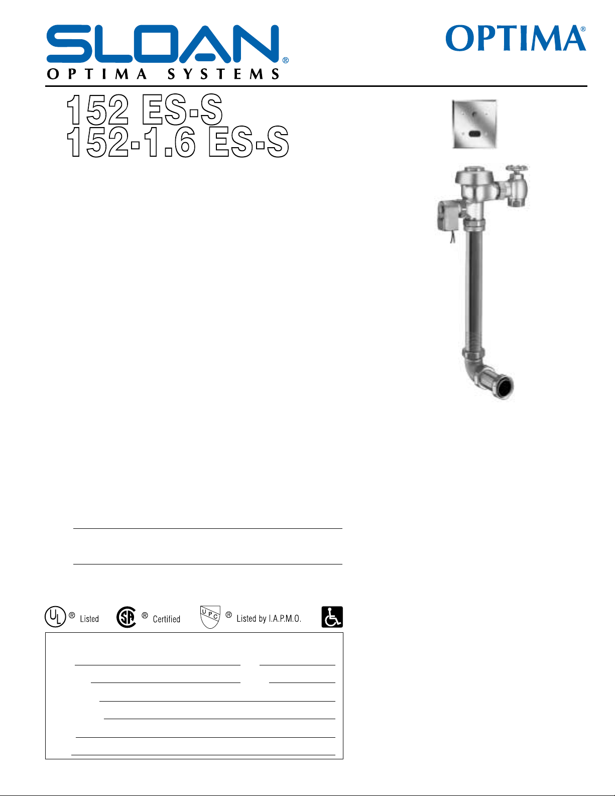
Description
Concealed, Sensor Operated Royal®Model Water Closet Flushometer, for wall
hung back spud bowls.
Flush Cycle
! Model 152 ES-S Water Saver (3.5 gpf/13.2 Lpf)
! Model 152-1.6 ES-S Low Consumption (1.6 gpf/6.0 Lpf)
Specifications
Quiet, Concealed, Diaphragm Type, Rough Brass Closet Flushometer with the
following features:
• PERMEX™ Synthetic Rubber Diaphragm with Dual Filtered Fixed Bypass
• OPTIMA®EL-1500-L Self-Adaptive Infrared Sensor with Indicator Light
• User friendly three (3) second Flush Delay
• Courtesy Flush™ Override Button
• Non-Hold-Open Integral Solenoid Operator
• Chrome Plated Wall Cover Plate (for 2-gang Electrical Box) with Vandal
Resistant Screws
• 1” I.P.S. Wheel Handle Bak-Chek™ Angle Stop
• Adjustable Tailpiece
• High Back Pressure Vacuum Breaker Flush Connection and Spud Coupling
for 1½” Concealed Back Spud
• Sweat Solder Adapter
• High Copper, Low Zinc Brass Castings for Dezincification Resistance
• Non-Hold-Open Integral Solenoid Operator, Fixed Metering Bypass and No
External Volume Adjustment to Ensure Water Conservation
• Flush Accuracy Controlled by CID™ Technology
• Diaphragm, Stop Seat and Vacuum Breaker to be molded from PERMEX™
Rubber Compound for Chloramine Resistance
Valve Body, Cover, Tailpiece and Control Stop shall be in conformance with
ASTM Alloy Classification for Semi-Red Brass. Valve shall be in compliance with
the applicable sections of ASSE 1037, ANSI/ASME A112.19.6 and Military
Specification V-29193. Installation conforms to ADA requirements.
L Dimension
Specify the “L” Dimension for the proper length of the Flush Connection. The
“L” Dimension is equal to the Wall Thickness (to nearest whole inch) plus 2¾”.
Variations
!
TP
Trap Primer Elbow
!
YI
Two Wall Bumpers (for open seat without cover)
Accessories
!
EL-1154
Transformer (120 VAC/24 VAC 50 VA)
!
EL-3342
Transformer (240 VAC/24 VAC 50 VA)
See Accessories Section and OPTIMA Accessories Section of the Sloan catalog
for details on these and other OPTIMA Flushometer variations.
Royal
®
Model
!
!
!
!
This space for Architect/Engineer approval
Job Name Date
Model Specified Quantity
Variations Specified
Customer/Wholesaler
Contractor
Architect
The information contained in this document is subject to change without notice.
Sensor Operated Flushometers
Automatic
Sloan OPTIMA®equipped Flushometers provide the
ultimate in sanitary protection and automatic operation.
There are no handles to trip or buttons to push. The
Flushometer operates by means of an infrared sensor that
adapts to its surrounding. Once the user enters the
sensor’s effective range and then steps away, the
Flushometer Solenoid initiates the flushing cycle to flush
the fixture.
Hygienic
User makes no physical contact with the Flushometer
surface except to initiate the Override Button when
required. Helps control the spread of infectious diseases.
Twenty-four Hour Sentinel Flush keeps fixture fresh during
periods of nonuse.
Economical
Automatic operation provides water usage savings over
other flushing devices. Reduces maintenance and
operation costs.
Practical
Solid state electronic circuitry assures years of
dependable, trouble-free operation. The operational
components of the Flushometer are identical to a handle
operated Royal®Flushometer, proven by 90 years of
experience.
Warranty
3 year (limited)
Made in the U.S.A
!
!
!
!
!
Royal Optima 152 ES-S S.S. — Rev. 1 (01/02)
!
!
!
Page 2
SLOAN VALVE COMPANY • 10500 SEYMOUR AVENUE • FRANKLIN PARK, IL 60131
Phone: 1-800-9-VALVE-9 or 1-847-671-4300 • Fax: 1-800-447-8329 or 1-847-671-4380 • http://www.sloanvalve.com
Copyright © 2002 Sloan Valve Company Printed in the U.S.A. Made in the U.S.A. Royal Optima 152 ES-S S.S. — Rev. 1 (01/02)
Description
Concealed, Sensor Operated Royal®Model Water Closet Flushometer,
for wall hung back spud bowls.
Flush Cycle
! Model 152 ES-S Water Saver (3.5 gpf/13.2 Lpf)
! Model 152-1.6 ES-S Low Consumption (1.6 gpf/6.0 Lpf)
ELECTRICAL SPECIFICATIONS
1.
A continuous, invisible light
beam is emitted from the
OPTIMA Sensor.
2.
As the user enters the beam’s
effective range (22” to 42”)
the beam is reflected into the
OPTIMA Scanner Window
and transformed into a low
voltage electrical circuit.
Once activated, the Output
Circuit continues in a “hold”
mode for as long as the user
remains within the effective
range of the Sensor.
3.
When the user steps away
from the OPTIMA Sensor, the
circuit waits 3 seconds (to
prevent false flushing) then
initiates an electrical “onetime” signal that operates the
Solenoid. This initiates the
flushing cycle to flush the
fixture. The Circuit then
automatically resets and is
ready for the next user.
!
!
Control Circuit
Solid State
24 VAC Input
24 VAC Output
8 Second Arming Delay
3 Second Flush Delay
24 Hour Sentinel Flush
OPTIMA Sensor Range
Nominal 22” - 42” (559 mm 1067 mm)
Self-adaptive Window ± 10”
(254 mm)
OPERATION
Solenoid Operator
24 VAC, 50/60 Hz
Transformer
Sloan Part #EL-154
120 VAC, 50/60 Hz Primary
24 VAC, 50/60 Hz Secondary
Class II, UL Listed, 50 VA.
Sloan Part #EL-342
240 VAC, 50/60 Hz Primary
24 VAC, 50/60 Hz Secondary
Class II, UL Listed, 50 VA.
!
!
!
!
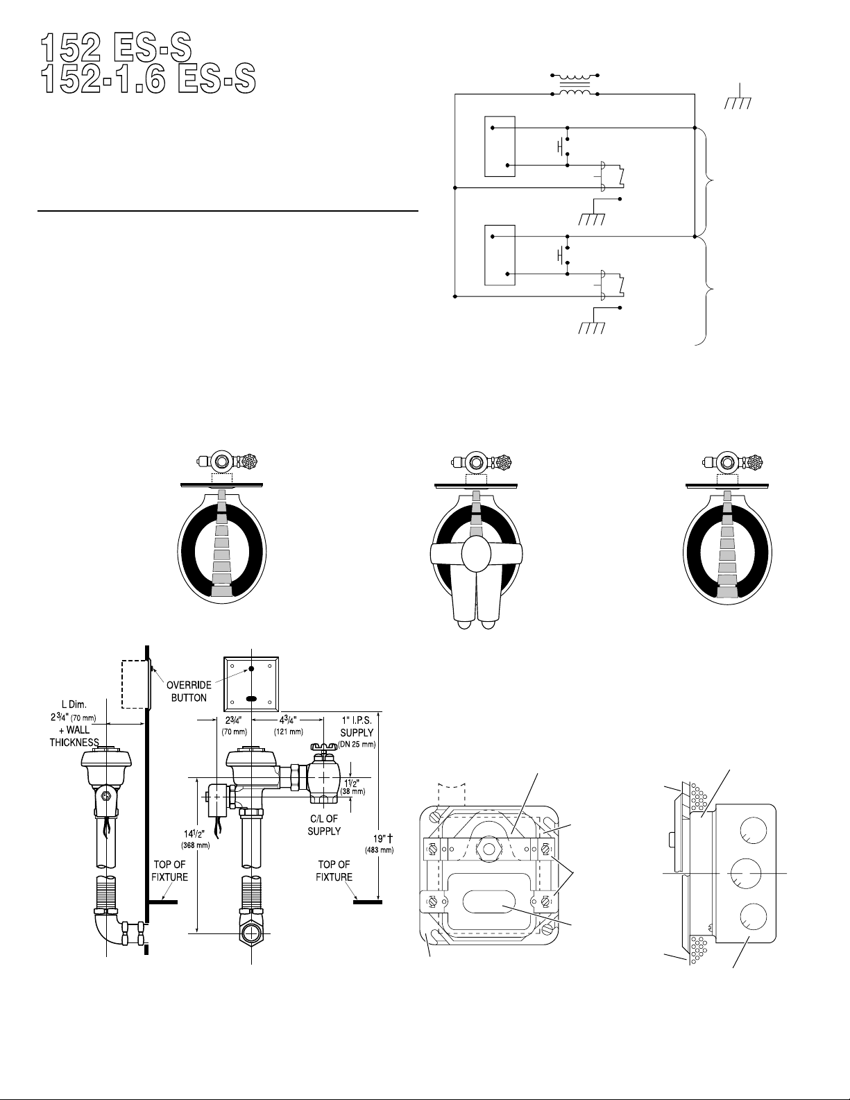
One Transformer serves up to ten (10) OPTIMA Closet/Urinal
Flushometers. Specify number of transformers required accordingly.
UNIT #2
THRU #10
(IF USED)
UNIT #1
WIRING DIAGRAM
120 VAC
24 VAC
EL-1500-L SENSOR
GND
EL-1500-L SENSOR
OVERRIDE BUTTON
24 VAC COIL
SOLENOID
GROUND
WIRE
COIL WIRE
OVERRIDE BUTTON
24 VAC COIL
SOLENOID
GROUND
WIRE
COIL WIRE
† Position of Sensor Box can be raised or lowered 1” (25 mm) if in conflict with
Handicap Grab Bars.
ELECTRICAL BOX INSTALLATION
SENSOR LLOCATION AAND PPOSITIONING IIS CCRITICAL
Failure to properly position the electrical boxes to the plumbing rough-in
will result in improper installation and impair product performance. All
tradesmen (plumbers, electricians, tile setters, etc.) involved with the
installation of this product must coordinate their work to assure proper
product installation.
NOTE
: INSTALL PLASTER RING SO THAT SCREW
HOLES ARE ON THE LEFT AND RIGHT SIDE OF BOX
(VIEW WITH COVER REMOVED)
4” (102 mm) SQ. x 2-1/8” (54 mm) DEEP
OUTLET BOX — APPLETON ELECT. #4SD1
OR EQUAL (BY CONTRACTOR)
EL-141-A YOKE ASSEMBLY (INSTALL WITH
OFFSET PORTION IN DEVICE COVER)
4” (102 mm) SQ. BOX DEVICE COVER (PLASTER
RING) 3/4” (19 mm) HIGH — APPLETON ELECT.
#8470 OR EQUAL (BY CONTRACTOR)
FINISHED WALL
OPENING
FINISHED
TILE WALL
TABS OF YOKE AND
SENSOR TO BE MOUNTED
ON TOP OF FINISHED
PLASTER OR TILE WALL
EL-1500-L SENSOR
FINISHED PLASTER
WALL
 Loading...