

Page 1
The Dual Filtered Diaphragm™
Sloan’s Dual Filtered Diaphragm helps prevent valve “run on”
and has been an exclusive feature of the Royal Flushometer
since January 1998. Sediment, present in most water
supplies, may clog the metering bypass hole in traditional
Flushometer valves and cause continuous operation or
“run on.” The dual patented filter rings on the
Dual Filtered Diaphragm prevent sediment from
reaching the bypass. This results in clog-free operation,
eases valve maintenance, and reduces water usage. The
Dual Filtered Diaphragm is factory assembled to assure an accurate
flush delivery.
The Dual Filtered Diaphragm is available as a single drop-in kit
(Diaphragm Assembly only) or as one of the exclusive components in
the Royal Performance Kit. The Dual Filtered Diaphragm can be
used in Royal, Regal, and similar diaphragm-style valve
bodies. For use in Sloan valve bodies with a bell-shaped
cover (manufactured before 1964), replace the
bottom filter ring in these kits with a
blue A-108 filter ring (not shown;
order 5301283 separately in a
package of 6).
Maintenance Guide
••
RR OO YY AA LL
ITEM 3:
Dual Filtered Diaphragm™ Assembly •••
Available in
DIAPHRAGM ONLY and ROYAL Performance™ Kits
ROYAL Performance™ KIT includes Dual Filtered Diaphragm Assembly (Item 3), Handle Repair Kit with Triple Seal Packing (Item 8), High Back Pressure Vacuum
Breaker Repair Kit (Item 11), and one Tailpiece O- Ring (Item 15). DIAPHRAGM ONLY KIT contains “drop-in” Dual Filtered Diaphragm Assembly (Item 3) ONLY.
Performance KIT DIAPHRAGM ONLY KIT
Code No. Kit No. Code No. Kit No. Flush Volume Use With Relief Valve § Refill Head ■■Flow Ring
A 3301070 A-1101-A 3301502 A-1041-A 1.6 gpf (6.0 Lpf) Low Consumption Water Closets Green Gray Smooth
B 3301071 A-1102-A 3301501 A-1038-A 3.5 gpf (13.2 Lpf) Water Saver Water Closets White Gray Smooth
C 3301072 A-1103-A 3301505 A-1044-A 2.4 gpf (9.0 Lpf) 9 Liter European Water Closets Blue Gray Smooth
D 3301073 A-1106-A 3301504 A-1043-A 0.5 gpf (1.9 Lpf) Wash Down Urinals Green Black Smooth & Slotted
E 3301074 A-1107-A 3301503 A-1042-A 1.0 gpf (3.8 Lpf) Low Consumption Urinals Green Black Slotted
F 3301075 A-1108-A 3301500 A-1037-A 1.5 gpf (5.7 Lpf) Water Saver Urinals Black Black Smooth
The colors of the Relief Valve and the
Refill Head plus the shape of Flow Ring
identify the Flush Volume of a DUAL
FILTERED DIAPHRAGM ASSEMBLY.
■■
Closet Refill Heads (Gray) have
larger slots than Urinal Refill Heads
(Black).
NOTE: Each item is identified by a Part Number and a Code Number. Expedite pro-
cessing by using our Code Number. Parts shown service all Sloan diaphragm-type
Flushometers manufactured after 1964, including Low Consumption (LC) models.
Tailpieces and
Control Stops
For additional information,
refer also to Sloan’s
Tailpiece (0816505)
and Control Stop (0816333)
Maintenance Guides.
TAILPIECE
CONTROL STOP AND CAPS
The information contained in this document is subject to change without notice.
Royal M.G.– Rev. 4a (04/03) Code No. 0816186
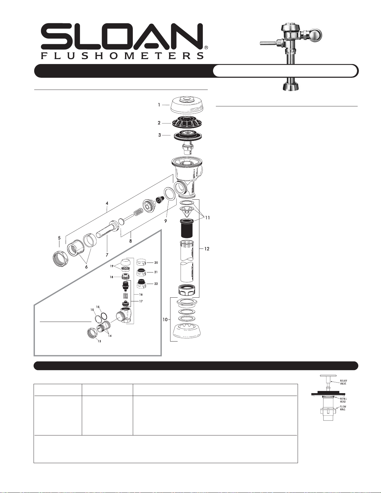
Parts List — Royal Flushometer Valve
Item Code No. Part No. Description
1 0301172 A-72 CP Cover
2 0301168 A-71 Inside Cover
3 see below — Dual Filtered Diaphragm Assembly
(refer to table and diagram below)
4 0302390 B-73-A CP ADA-Compliant Triple Seal Handle Assembly
5 0301082 A-6 CP Handle Coupling
6 0302109 B-7-A CP Socket Assembly
7 0302389 B-74-A CP ADA-Compliant Handle
8 3302306 B-51-A Triple Seal Handle Repair Kit
9 5301139 A-31 Handle Gasket (package of 48)
10 0306125 F-5-A 3/4” (19 mm) CP Spud Coupling Assembly
0306140 F-5-A 1-1/4” (32 mm) CP Spud Coupling Assembly
0306146 F-5-A 1-1/2” (38 mm) CP Spud Coupling Assembly
11 3323182 V-651-A High Back Pressure Vacuum Breaker Repair Kit
12 3393004 V-600-AA 3/4”(19 mm) x 9” (228 mm) CP Vacuum Breaker
3393006 V-600-AA 1-1/4” (32 mm) x 9” (228 mm) CP Vacuum Breaker
3393007 V-600-AA 1-1/2” (38 mm) x 9” (228 mm) CP Vacuum Breaker
13 0308676 H-550 CP Stop Coupling
14 0308801 H-551-A CP Adjustable Tailpiece (2-1/16”/52 mm long)
15A 5308696 H-553 O-Ring (package of 24)
15B 5308381 H-552 Locking Ring (package of 12)
16 3308386 H-700-A 1” (25 mm) CP Bak-Chek
®
Screwdriver Stop
3308384 H-700-A 3/4” (19 mm) CP Bak-Chek
®
Screwdriver Stop
17 3308853 H-541-A Control Stop Repair Kit †
3308856 H-543-A Control Stop Repair Kit ‡
18 0308612 H-622 CP Bonnet †
0308843 H-577 CP Bonnet ‡
19 3308772 H-1010-A Vandal Resistant Control Stop Cap Assembly †
3308790 H-1009-A Vandal Resistant Control Stop Cap Assembly ‡
20 0308840 H-573 Control Stop Cap CP †
0308848 H-582 Control Stop Cap CP ‡
21 3308866 H-574 Control Stop Cap with Bumper †
(–YO Variation)
22 3308867 H-576 Control Stop Cap with Extended Bumper †
(–YG Variation)
†
Use with H-700-A (1”/25 mm and 3/4”/19 mm) and H-600-A (1”/25 mm) Bak-Chek
®
Screwdriver Control Stops.
‡ Use with H-600-A (3/4”/19 mm) Bak-Chek
®
Screwdriver Control Stops.
Sloan products are also available in Polished Brass, Lustre Gold, and Satin finishes — contact our
Customer Service staff for code numbers. If you have any questions about installation,
maintenance, or troubleshooting issues, call our Installation Engineering staff at 1-888-SLOAN-14.
§ Consult Sloan Valve Company for availability of replacement plastic Relief Valves (Green, Black, Blue, and White) and brass Relief Valves.
NOTE: For older water closets that require 4.5 gpf (17.0 Lpf), choose kits shown on line B, but remove the Flow Ring before use. For blowout-style
urinals that require 3.5 gpf (3.2 Lpf), choose kits shown on line B. For service sinks that require 6.5 gpf (24.6 Lpf), order A-36-A diaphragm repair kit
(3301036; not shown above) and remove the Flow Ring before use. Regulations for Low Consumption fixtures prohibit the use of higher flush volumes.
A
B
Page 2
1. PROBLEM: Flushometer does not function (no flush).
CAUSE: Control Stop or main supply valve is closed.
SOLUTION: Open Control Stop or main supply valve.
CAUSE: Handle Assembly is damaged.
SOLUTION: Replace B-73-A Handle or repair with B-51-A Handle Repair
Kit.
CAUSE: Relief Valve is damaged.
SOLUTION: Replace Relief Valve.
2. PROBLEM: Handle leaks.
CAUSE: Handle Seal or Handle Assembly is damaged.
SOLUTION: Replace B-73-A Handle or repair with B-51-A Handle Repair
Kit.
3. PROBLEM: Water splashes from fixture.
CAUSE: Control Stop is open wider than necessary.
SOLUTION: Adjust Control Stop for desired delivery of water volume.
CAUSE: Water Saver/Conventional Diaphragm Assembly is installed on
Low Consumption fixture or Closet Diaphragm Assembly is
installed on Urinal fixture.
SOLUTION: Determine the required flush volume (see label on valve or
markings on fixture). Replace Diaphragm Assembly or Relief
Valve for appropriate flush volume of fixture.
4. PROBLEM: Volume of water is insufficient to adequately siphon fixture.
CAUSE: Control Stop is not open wide enough.
SOLUTION: Adjust Control Stop for desired delivery of water volume.
CAUSE: Diaphragm Assembly is damaged.
SOLUTION: Replace Diaphragm Assembly.
CAUSE: Low Consumption Diaphragm Assembly is installed on Water
Saver/Conventional fixture or Urinal Diaphragm Assembly is
installed on Closet fixture.
SOLUTION: Determine the required flush volume (see label on valve or
markings on fixture). Replace Diaphragm Assembly or Relief
Valve for appropriate flush volume of fixture.
CAUSE: Inadequate water volume or pressure is available from supply.
SOLUTION: Increase flow rate or pressure to the valve. If gauges are not
available to measure supply pressure/volume, remove Relief
Valve from Diaphragm Assembly and open the Control Stop.
If the fixture siphons: Additional water volume is required.
Install higher flushing volume Relief Valve or Diaphragm
Assembly or cut Flow Ring from Guide.
If the fixture DOES NOT siphon (or a Low Consumption flush is
required): Additional steps must be taken to increase the water
pressure and/or volume at the water supply. Contact fixture
manufacturer for minimum supply requirements of fixture.
5. PROBLEM: Flushometer valve closes immediately (short flush).
CAUSE: Worn or damaged Diaphragm Assembly.
SOLUTION: Replace Diaphragm Assembly.
CAUSE: Handle Assembly is damaged.
SOLUTION: Replace B-73-A Handle or repair with B-51-A Handle Repair Kit.
CAUSE: Low Consumption Diaphragm Assembly is installed on Water
Saver/Conventional fixture or Urinal Diaphragm Assembly is
installed on Closet fixture.
SOLUTION: Determine the required flush volume (see label on valve or
markings on fixture). Replace Diaphragm Assembly or Relief
Valve for appropriate flush volume of fixture.
6. PROBLEM: Length of flush is too long (long flush) or fails to shut off.
CAUSE: Bypass hole (upper filter ring) of Diaphragm Assembly is dirty.
SOLUTION: Remove the Diaphragm Assembly. Disassemble the filter rings
from the Diaphragm, wash under running water, and
reassemble. Replace as necessary.
CAUSE: Relief Valve or Diaphragm Assembly is damaged.
SOLUTION: Replace Relief Valve or Diaphragm Assembly.
CAUSE: Water Saver/Conventional Diaphragm Assembly is installed on
Low Consumption fixture or Closet Diaphragm Assembly is
installed on Urinal fixture.
SOLUTION: Determine the required flush volume (see label on valve or
markings on fixture). Replace Diaphragm Assembly or Relief
Valve for appropriate flush volume of fixture.
CAUSE: Inside Cover is damaged.
SOLUTION: Install new A-71 Inside Cover.
CAUSE: Line water pressure dropped and is insufficient to close valve.
SOLUTION: Close the Control Stop until pressure is restored.
CAUSE: Relief Valve is not seated properly.
SOLUTION: Disassemble Diaphragm components (Relief Valve, Filter
Rings, and Diaphragm unit), wash under running water, and
reassemble. Replace as necessary.
7. PROBLEM: Chattering noise is heard during flush.
CAUSE: Inside Cover is damaged.
SOLUTION: Install new A-71 Inside Cover.
CAUSE: Relief Valve or Diaphragm Assembly is damaged.
SOLUTION: Replace Relief Valve or Diaphragm Assembly.
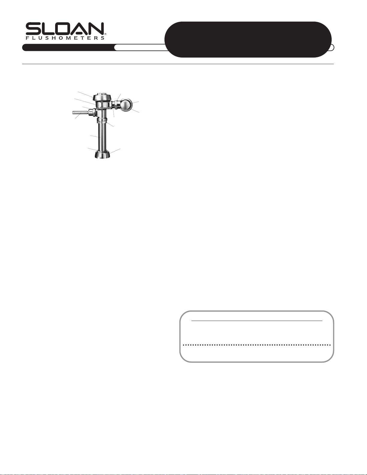
COVER
BODY
HANDLE COUPLING
HANDLE ASSEMBLY
FLUSH CONNECTION
(VACUUM BREAKER)
SPUD COUPLING
STOP COUPLING
CONTROL STOP
SUPPLY FLANGE
TAILPIECE
OUTLET COUPLING
SPUD FLANGE
Troubleshooting Guide
ATTENTION INSTALLERS: With the exception of the Control Stop inlet, DO NOT USE pipe sealant or plumbing grease on any valve component or coupling! To protect the
chrome or special finish of Sloan Flushometers, DO NOT USE toothed tools to install or service these valves. Use our Sloan A-50 “Super-Wrench™” or other smoothjawed wrench to secure couplings. Regulations for Low Consumption fixtures (1.6 gpf/6.0 Lpf closets and 1.0 gpf/3.8 Lpf urinals) prohibit use of higher flush volumes.
MM aa ii nn tt ee nn aa nn cc ee GG uu ii dd ee
•• RR OO YY AA LL
Care and Cleaning Instructions
DO NOT USE abrasive or chemical cleaners to clean Flushometers that may dull the luster
and attack the chrome or decorative finish. Use ONLY soap and water, then wipe dry with a
clean towel or cloth. When cleaning the bathroom tile, protect the Flushometer from any
splattering of cleaner. Acids and cleaning fluids can discolor or remove chrome plating.
If further assistance is required, please contact Sloan Valve Company Installation Engineering Department at
1-888-SLOAN-14
(1-888-756-2614)
.
LIMITED WARRANTY
Sloan Valve Company warrants its Flushometer Products to be made of first class materials, free from defects
of material or workmanship under normal use and to perform the ser vice for which they are intended in a
thoroughly reliable and efficient manner when properly installed and serviced for a period of 3 years (1 year for
special finishes) from date of purchase. During this period, Sloan Valve Company will, at its option, repair or
replace any part or par ts which prove to be thus defective if returned to Sloan Valve Company, at customer’s
cost, and this shall be the sole remedy available under this warranty. No claims will be allowed for labor,
transportation or other incidental costs. This warranty extends only to those persons or organizations who
purchase Sloan Valve Company’s products directly from Sloan Valve Company for purpose of resale.
THERE ARE NO WARRANTIES WHICH EXTEND BEYOND THE DESCRIPTION ON THE FACE HEREOF. IN NO EVENT
IS SLOAN VALVE COMPANY RESPONSIBLE FOR ANY CONSEQUENTIAL DAMAGES OF ANY MEASURE
WHATSOEVER.
NOTE: In January 1998, the Royal Diaphragm design was upgraded to a
preassembled unit with two (2) plastic filtering rings attached to the rubber
diaphragm (one on top and one on bottom). If the Flushometer you are servicing
has our older, segmented diaphragm with brass bypass hole, refer to our Regal
Maintenance Guide (0816185) for additional troubleshooting information.
The information contained in this document is subject to change without notice.
AIR DELIGHTS, INC. • 9974 SW ARCTIC DR. • BEAVERTON, OR. 97005
Copyright © 2003 SLOAN VALVE COMPANY Printed in the U.S.A. Made in the U.S.A. Royal M.G. — Rev. 4a (04/03) Code No. 0816186
Phone: 1-800-440-5556 • Fax: 1-503-643-8224 • http://www.airdelights.com
 Loading...