

Page 1
Code No. 0816748
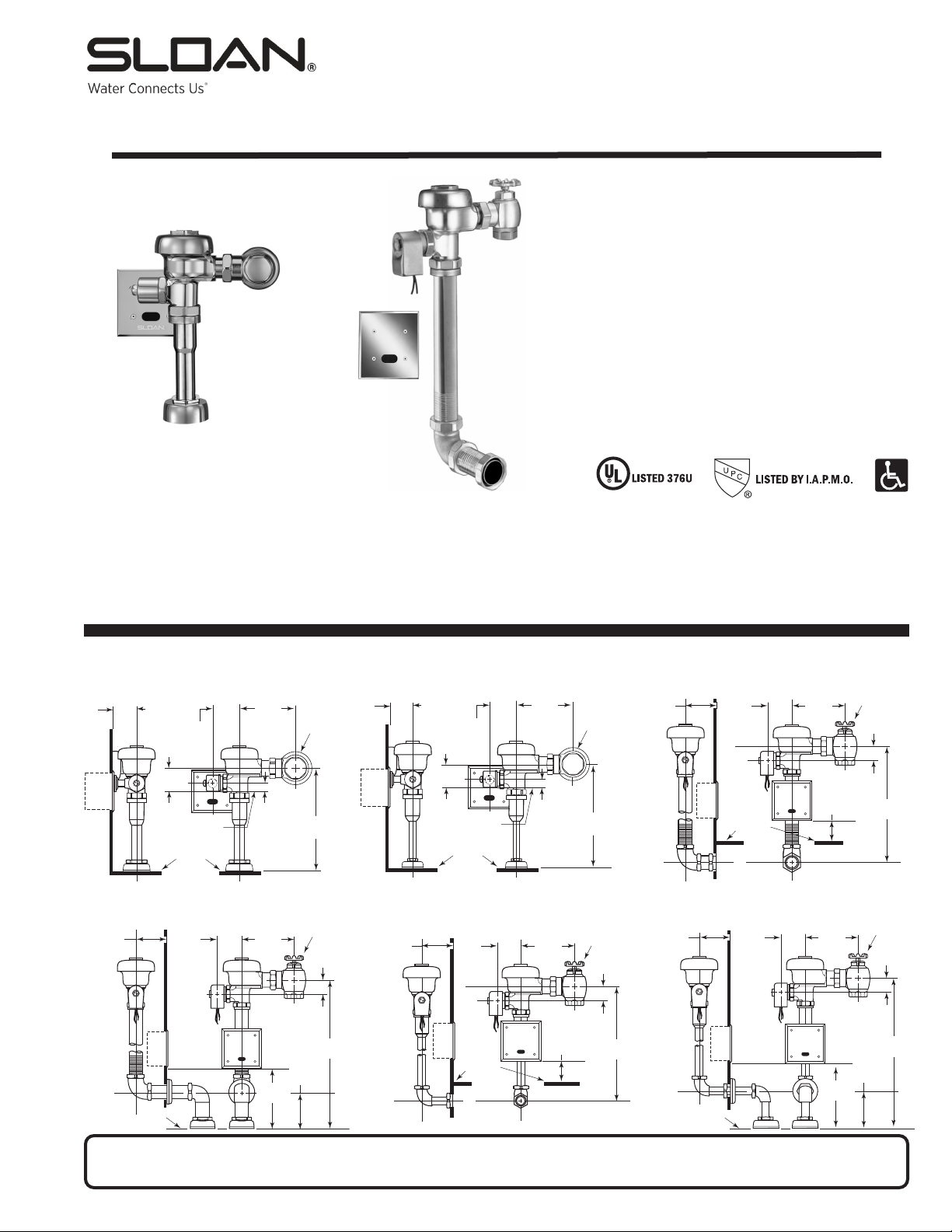
2-3/4"
(70 mm)
+ WALL
THICKNESS
2-3/4”
(70 mm)
2-1/4” MIN.
(57 mm)
2-3/4”
(70 mm)
11-1/2”
(292 mm)
C/L OF
SUPPLY
C/L OF
ELEC.
BOX
TOP OF
FIXTURE
1”
(25 mm)
4-3/4”
(121 mm)
2-1/4”
(63 mm)
3/4” I.P.S.
SUPPLY
(DN 20 mm)
2-1/4” MIN.
(57 mm)
2-3/4”
(70 mm)
1” I.P.S.
SUPPLY
(DN 25 mm)
11-1/2”
(292 mm)
C/L OF
SUPPLY
C/L OF
ELEC.
BOX
TOP OF
FIXTURE
1”
(25 mm)
4-3/4”
(121 mm)
2-1/4”
(63 mm)
2-3/4"
(70 mm)
+ WALL
THICKNESS
C/L OF
SUPPLY
2-3/4”
(70 mm)
TOP OF
FIXTURE
1-1/2”
(38 mm)
4-3/4”
(121 mm)
14-1/2”
(368 mm)
2-1/4” MIN.
(57 mm)
2-3/4”
(70 mm)
11-1/2”
(292 mm)
C/L OF
SUPPLY
C/L OF
ELEC.
BOX
TOP OF
FIXTURE
1”
(25 mm)
4-3/4”
(121 mm)
2-1/4”
(63 mm)
2”
(51 mm)
3/4” I.P.S.
SUPPLY
(DN 20 mm)
1” I.P.S.
SUPPLY
(DN 25 mm)
C/L OF ELEC. BOX & FIXTURE
2-3/4"
(70 mm)
+ WALL
THICKNESS
C/L OF
SUPPLY
2-3/4”
(70 mm)
TOP OF
FIXTURE
1-1/2”
(38 mm)
4-3/4”
(121 mm)
14-1/2”
(368 mm)
2”
(51 mm)
1” I.P.S.
SUPPLY
(DN 25 mm)
C/L OF ELEC. BOX & FIXTURE
2-3/4"
(70 mm)
+ WALL
THICKNESS
2-1/4” MIN.
(57 mm)
2-3/4”
(70 mm)
11-1/2”
(292 mm)
C/L OF
SUPPLY
C/L OF
ELEC.
BOX
TOP OF
FIXTURE
1”
(25 mm)
4-3/4”
(121 mm)
2-1/4”
(63 mm)
TOP OF
FIXTURE
2-3/4
(70 mm)
+ WALL
THICKNESS
C/L OF
SUPPLY
2-3/4”
(70 mm)
TOP OF
FIXTURE
1-1/2”
(38 mm)
4-3/4”
(121 mm)
13-1/2”
(343 mm)
2”
(51 mm)
3/4” I.P.S.
SUPPLY
(DN 20 mm)
3/4” I.P.S.
SUPPLY
(DN 20 mm)
Model 195 Model 197
2-3/4”
(70 mm)
+ WALL
THICKNESS
2-3/4”
(70 mm)
TOP OF
FIXTURE
2-1/4” MIN.
(57 mm)
2-3/4”
(70 mm)
1” I.P.S.
SUPPLY
(DN 25 mm)
11-1/2”
(292 mm)
C/L OF
SUPPLY
C/L OF
ELEC.
BOX
TOP OF
FIXTURE
1”
(25 mm)
4-3/4”
(121 mm)
2-1/4”
(63 mm)
2-3/4”
(70 mm)
+ WALL
THICKNESS
C/L OF
SUPPLY
2-3/4”
(70 mm)
1-1/2”
(38 mm)
4-3/4”
(121 mm)
14-1/2”
(368 mm)
8”
(203 mm)
5”
(127 mm)
1” I.P.S.
SUPPLY
(DN 25 mm)
2-3/4"
(70 mm)
+ WALL
THICKNESS
C/L OF
SUPPLY
2-3/4”
(70 mm)
TOP OF
FIXTURE
1-1/2”
(38 mm)
4-3/4”
(121 mm)
14-1/2”
(368 mm)
2-1/4” MIN.
(57 mm)
2-3/4”
(70 mm)
11-1/2”
(292 mm)
C/L OF
SUPPLY
C/L OF
ELEC.
BOX
TOP OF
FIXTURE
1”
(25 mm)
4-3/4”
(121 mm)
2-1/4”
(63 mm)
2”
(51 mm)
C/L OF ELEC. BOX & FIXTURE
2-3/4
(70 mm)
+ WALL
THICKNESS
C/L OF
SUPPLY
2-3/4”
(70 mm)
TOP OF
FIXTURE
1-1/2”
(38 mm)
4-3/4”
(121 mm)
13-1/2”
(343 mm)
2”
(51 mm)
3/4” I.P.S.
SUPPLY
(DN 20 mm)
3/4” I.P.S.
SUPPLY
(DN 20 mm)
Model 195 Model 197
1” I.P.S.
SUPPLY
(DN 25 mm)
2-3/4”
(70 mm)
+ WALL
THICKNESS
C/L OF
SUPPLY
2-3/4”
(70 mm)
1-1/2”
(38 mm)
4-3/4”
(121 mm)
13-1/2”
(343 mm)
8”
(203 mm)
5”
(127 mm)
3/4” I.P.S.
SUPPLY
(DN 20 mm)
TOP OF
FIXTURE
C/L OF ELEC. BOX & FIXTURE
2-3/4"
(70 mm)
+ WALL
THICKNESS
C/L OF
SUPPLY
2-3/4”
(70 mm)
TOP OF
FIXTURE
1-1/2”
(38 mm)
4-3/4”
(121 mm)
14-1/2”
(368 mm)
2”
(51 mm)
1” I.P.S.
SUPPLY
(DN 25 mm)
2-3/4”
(70 mm)
+ WALL
THICKNESS
C/L OF
SUPPLY
2-3/4”
(70 mm)
1-1/2”
(38 mm)
4-3/4”
(121 mm)
13-1/2”
(343 mm)
8”
(203 mm)
5”
(127 mm)
3/4” I.P.S.
SUPPLY
(DN 20 mm)
TOP OF
FIXTURE
C/L OF ELEC. BOX & FIXTURE
6/16)
Rev. 3 (0
INSTALLATION INSTRUCTIONS FOR OPTIMA®SYSTEMS SENSOR ACTIVATED
®
SLOAN
Made in the U.S.A.
Sloan Valve Company warrants its ES-S Sensor Activated Sloan®and Regal®Flushometers to be made of first class materials, free from defects of material or workmanship under normal use and to perform the service
for which they are intended in a thoroughly reliable and efficient manner when properly installed and serviced, for a period of three years (1 year for special finishes) from date of purchase. During this period, Sloan
Valve Company will, at its option, repair or replace any part or parts which prove to be thus defective if returned to Sloan Valve Company, at customer’s cost, and this shall be the sole remedy available under this
warranty. No claims will be allowed for labor, transportation or other incidental costs. This warranty extends only to persons or organizations who purchase Sloan Valve Company’s products directly from Sloan Valve
Company for purpose of resale.
THERE ARE NO WARRANTIES WHICH EXTEND BEYOND THE DESCRIPTION ON THE FACE HEREOF. IN NO EVENT IS SLOAN VALVE COMPANY RESPONSIBLE
FOR ANY CONSEQUENTIAL DAMAGES OF ANY MEASURE WHATSOEVER.
VALVE ROUGH-IN
and REGAL®CONCEALED and EXPOSED URINAL FLUSHOMETERS
Exposed Urinal Flushometers
1-1/4" Top Spud
• Model 180 ES-S
3/4" Top Spud
• Model 186 ES-S
Concealed Urinal Flushometers
1-1/4" Back Spud
• Model 190 ES-S
EXPOSED
FLUSHOMETER
MODEL 180 ES-S MODEL 186 ES-S
CONCEALED
FLUSHOMETER
LIMITED WARRANTY
Sloan Electronics are:
3/4" Back Spud
• Model 195 ES-S
1-1/4" Top Spud
• Model 192 ES-S
3/4" Top Spud
• Model 197 ES-S
MODEL 190 ES-S
MODEL 192 ES-S MODEL 195 ES-S
Failure to properly position the electrical boxes to the plumbing rough-in will result in improper installation and i mpair product performance. All tradesmen
(plumbers, electricians, tile setters, etc.) involved with the installation of this product must coordinate their work to assure proper product installation.
SENSOR LOCATION & POSITIONING IS CRITICAL!
MODEL 197 ES-S
Page 2
PRIOR TO FLUSHOMETER INSTALLATION
Prior to installing the Sloan OPTIMA equipped Flushometer, install the items
listed below. Refer to Rough-ins on Page 1 and illustrations on this page.
• 2-gang electrical box — 4" x 4" x 2-1/2" (102 mm x 102 mm x 64 mm)
for sensor; see paragraph entitled "Sensor Location"
• 2-gang electrical box — 4" x 4" x 2-1/2" (102 mm x 102 mm x 64 mm)
for transformer; see paragraph entitled “Transformer Installation” (mount
in a convenient location)
• Electrical wiring to the transformer box (120 VAC, 2 amp service required
for each EL-154, 24 VAC, 50 VA transformer used)
• Urinal fixture
• Drain line
• Water supply line
Important:
• ALL ELECTRICAL WIRING IS TO BE INSTALLED IN ACCORDANCE WITH
NATIONAL/LOCAL CODES AND REGULATIONS.
• ALL PLUMBING IS TO BE INSTALLED IN ACCORDANCE WITH APPLICABLE
CODES AND REGULATIONS.
• WATER SUPPLY LINES MUST BE SIZED TO PROVIDE AN ADEQUATE
VOLUME OF WATER FOR EACH FIXTURE.
• A 24 VAC STEP-DOWN TRANSFORMER MUST BE USED.
• USE APPROPRIATE PRECAUTIONS WHILE CONNECTING TRANSFORMER
TO 120 VAC POWER SOURCE.
• FLUSH ALL WATER LINES PRIOR TO MAKING CONNECTIONS.
Sloan®and Regal®Flushometers are designed to operate with 15 to 100 psi
(104 to 689 kPa) of water pressure. THE MINIMUM PRESSURE REQUIRED TO
THE VALVE IS DETERMINED BY THE TYPE OF FIXTURE SELECTED. Consult
fixture manufacturer for minimum pressure requirements.
Most Low Consumption water closets (1.6 gallon/6.0 liter) require a
minimum flowing pressure of 25 psi (172 kPa).
Protect the Chrome or Special finish of this Flushometer —
USE TOOTHED TOOLS TO INSTALL OR SERVICE THE
VALVE
. Also, see "Care and Cleaning" section of this manual.
IMPORTANT: EXCEPT FOR CONTROL STOP INLET, DO
NOT USE PIPE SEALANT OR PLUMBING GREASE ON
ANY VALVE COMPONENT OR COUPLING!
Transformer Installation
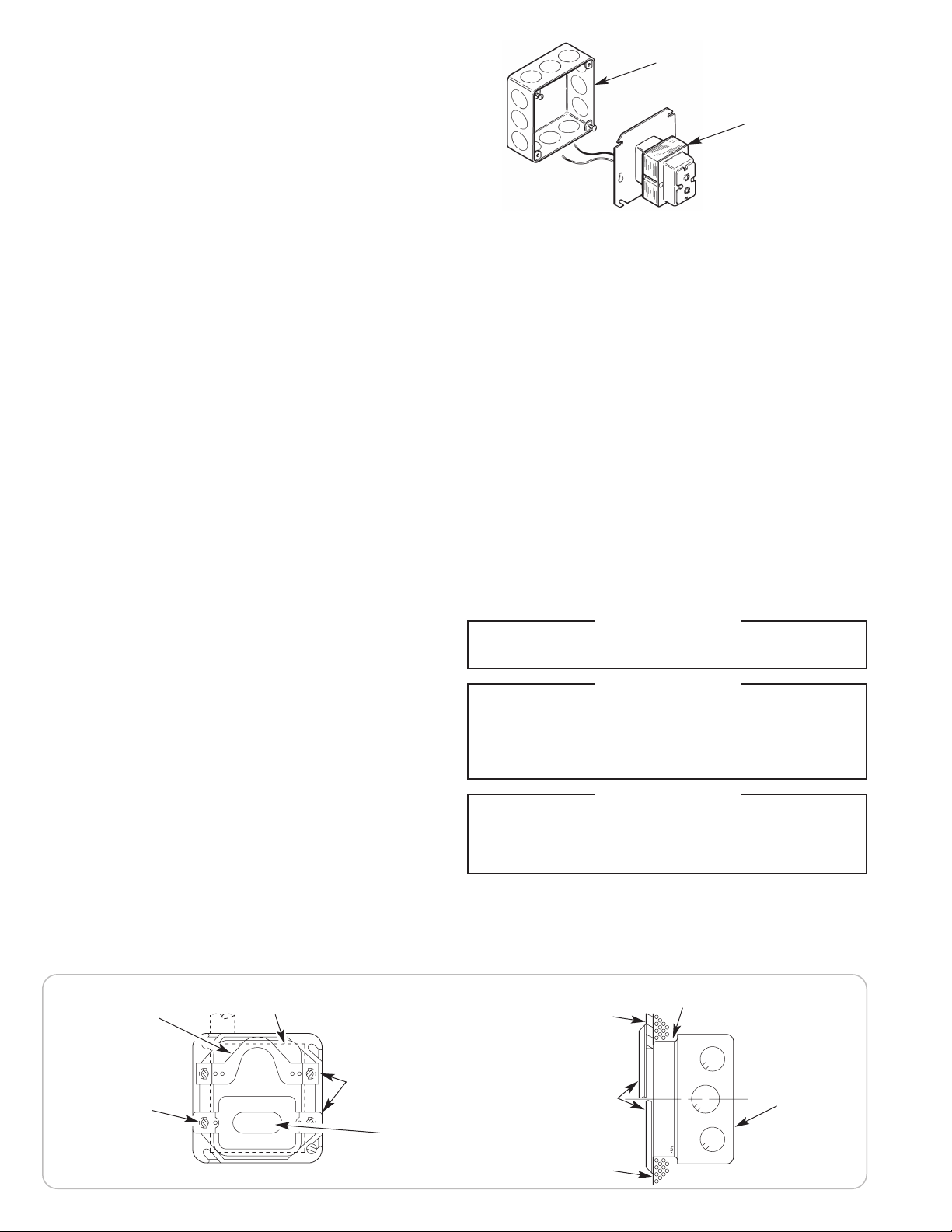
Install Transformer (EL-154) on a 2-Gang Electrical Box, 4" x 4" x 2-1/2"
(102 mm x 102 mm x 64 mm) in a convenient location; refer to the
illustration at upper right side of this page.
Note:
One Sloan EL-154 transformer can operate up to ten OPTIMA equipped
Flushometers. Run 18-gauge wire from transformer to Flushometer(s). Wire
supplied by others.
DO NOT supply power to transformer until installation of
Flushometer is complete.
Note:
A maximum of ten (10) Flushometer units can operate from one (1)
Sloan EL-154 Transformer, Class 2, UL Listed, 50 VA (min.) at 24 VAC, plate
mounted.
Sensor Location
Urinal models employ one (1) electrical box. Refer to rough-in illustrations for
locations.
DO NOT
2-GANG ELECTRICAL BOX 4" x 4" x 2½" (102 mm x 102 mm x 64 mm)
EL-154 TRANSFORMER †
† MOUNT TRANSFORMER
WITHIN 50 FEET (15 m) OF
FLUSHOMETER
ELECTRICAL BOX LOCATION IS CRITICAL — Failure to
properly position the electrical boxes to the plumbing
rough-in will result in improper installation and impair
product performance. All tradesmen (plumbers,
electricians, tile setters, etc.) involved with the
installation of this sensor activated flushometer must be
familiar with the requirements of its installation.
Improper installation may void the manufacturer's
warranty.
Note:
A template is packaged with Models 180 ES-S and 186 ES-S valves
to properly position electrical boxes. Refer to rough-in illustrations for
installation of electrical boxes.
Note:
Use Appleton #4SD1 Electrical Box and #8470 Plaster Ring or
equivalent.
Note: Install plaster ring so screw holes are on left and
right side of box.
Note:
Break tiles to allow screw holes in plaster to show.
Tools Required for Installation
• Slotted screwdriver
• 5/64" hex wrench (supplied)
• Wire stripper/crimping tool
• Sloan A-50 Super-Wrench™, Sloan A-109 Plier Wrench or smooth jawed
spud wrench
With the exception of Control Stop Inlet, DO NOT use pipe sealant or plumbing grease
Protect the chrome or special finish of Sloan Flushometers — DO NOT USE toothed
tools to install or service these valves. Use a Sloan A-50 Super-Wrench™, Sloan A-
109 Plier Wrench or smooth jawed spud wrench to secure all couplings. Also see
This product contains mechanical and/or electrical components that are subject to
normal wear. These components should be checked on a regular basis and replaced
as needed to maintain the valve’s performance.
If you have questions about how to install your Sloan Flushometer, consult your local
Sloan Representative or call Sloan Installation Engineering Department at:
!!! IMPORTANT !!!
on any valve component or coupling!
!!! IMPORTANT !!!
“Care and Cleaning” section of this manual.
!!! IMPORTANT !!!
1-888-SLOAN-14 (1-888-756-2614) OR 1-847-233-2016
ELECTRICAL BOX INSTALLATION DIAGRAM
EL-168-A
YOKE ASSEMBLY
(INSTALL WITH
OFFSET PORTION IN
DEVICE COVER)
NOTE:
INSTALL
PLASTER RING SO
THAT SCREW HOLES
ARE ON THE LEFT
AND RIGHT SIDE OF
BOX
FINISHED WALL OPENING
SENSOR TO BE MOUNTED
(VIEW WITH COVER REMOVED)
TABS OF YOKE AND
ON TOP OF FINISHED
PLASTER OR TILE WALL
EL-1500
SENSOR
NOTE:
SENSOR NOT
CONNECTED AND
INSTALLED UNTIL STEP 6
4” (102 mm) SQ. BOX DEVICE COVER (PLASTER RING) 3/4” (19 mm)
HIGH — APPLETON ELECT. #8470 OR EQUAL (BY CONTRACTOR)
FINISHED TILE WALL
COVER PLATE
FINISHED PLASTER WALL
2
4” (102 mm)
SQ. x 2-1/2” (64
mm) DEEP
OUTLET BOX —
APPLETON
ELECT. #4SD1
OR EQUAL (BY
CONTRACTOR)
Page 3
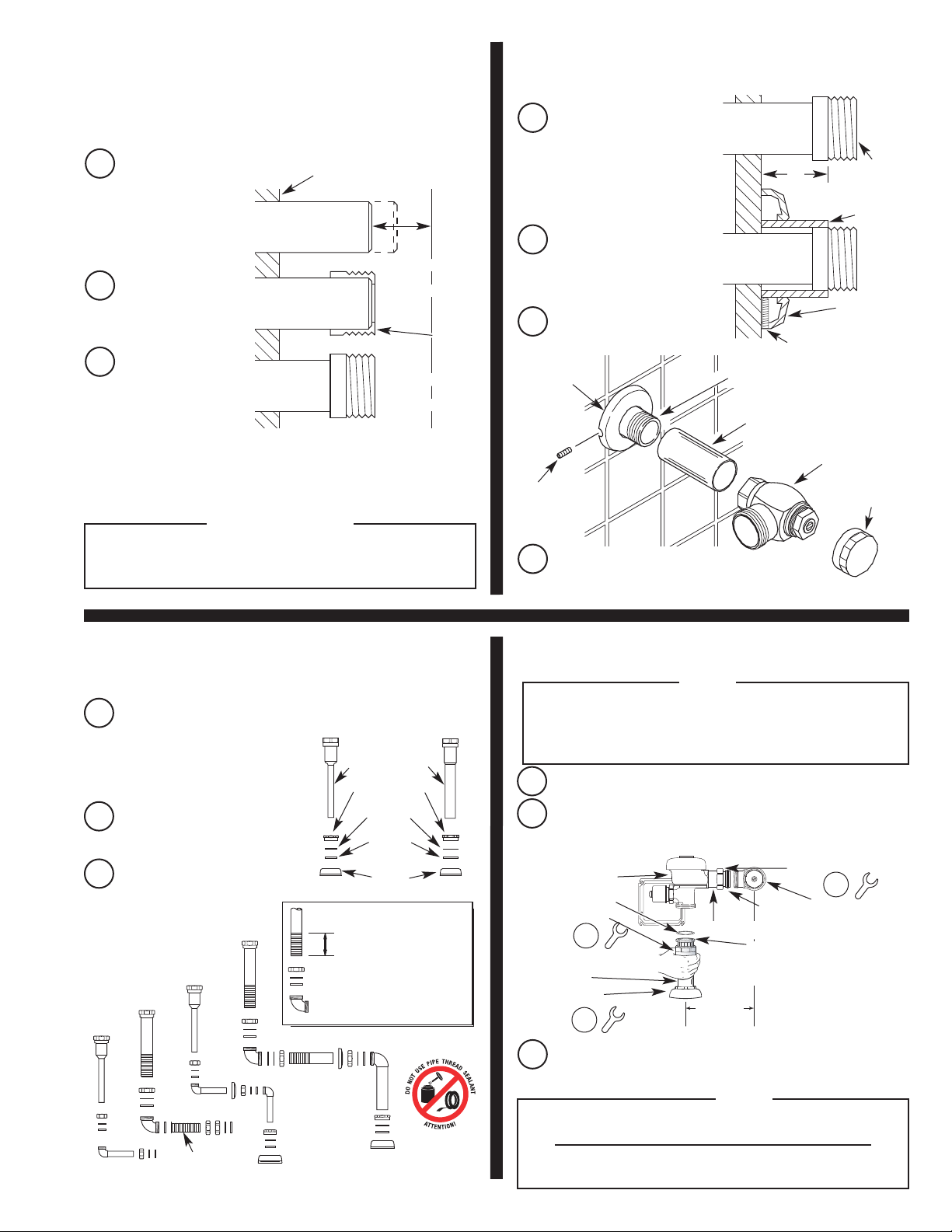
Install Optional Sweat Solder
1
Adapter (only if your supply
pipe does not have a male
thread)
Measure from finished
A
wall to C/L of Fixture
Spud. Cut pipe 1¼"
(32 mm) shorter than
this measurement.
Chamfer O.D. and I.D.
f water supply pipe.
o
Slide Threaded Adapter
B
fully onto pipe.
Sweat solder the
C
Adapter to pipe.
With the exception of Control Stop Inlet, DO NOT use pipe sealant or plumbing
grease on any valve component or coupling!
WATER SUPPLY PIPE
!!! IMPORTANT !!!
FINISHED WALL
(32 mm)
SWEAT
SOLDER
ADAPTER
C/L OF
FIXTURE
SPUD
1-1/4”
Install Cover Tube, Wall Flange
2
A
B
C
FLANGE
SET SCREW
D
and Control Stop to supply pipe
Measure from finished wall
to first thread of Adapter or
hreaded supply pipe
t
(dimension “X”). Cut Cover
Tube to this length.
Slide Cover Tube over pipe.
Slide Wall Flange over Cover
Tube until against wall.
Thread Control Stop onto pipe.
Tighten with a wrench.
WALL
Tighten Wall Flange Set Screw with hex
wrench supplied.
Resistant Stop Cap at this time.
DO NOT
WATER
SUPPLY PIPE
X
WALL
FLANGE
SET SCREW
IRON PIPE NIPPLE OR COPPER PIPE
WITH SWEAT SOLDER ADAPTER
COVERING TUBE
BAK-CHEK
CONTROL STOP
CONTROL STOP
install Vandal
SWEAT
SOLDER
ADAPTER
COVER TUBE
®
CAP
Install Vacuum Breaker Flush
3
A
B
C
MODEL
195 ES-S
Connection
Assemble Pipe, Elbows,
Couplings, Nylon Slip
Gasket, Rubber Gaskets and
Flanges as illustrated.
Insert Tube into Fixture Spud.
Hand tighten all Couplings.
MODEL
197 ES-S
MODEL
190 ES-S
INSTALL WITH
FLANGE AGAINST
ELBOW
MODEL
192 ES-S
MODEL
186
ES-S
VACUUM
BREAKER
TUBE
SPUD
COUPLING
NYLON SLIP
GASKET
RUBBER
GASKET
FLANGE
1-1/4” (32 mm) MIN.
IMPORTANT:
SCORED PIPE TO LENGTH LEAVE
A MINIMUM OF 1-1/4” (32 mm)
OF SCORING TO ENSURE PROPER
ENGAGEMENT
MODEL
180 ES-S
SPUD
WHEN CUTTING
Install Flushometer
4
For high efficiency urinal flushometers (0.5, 0.25 and 0.125 gpf), it is
necessary to first insert the flow control component into the tailpiece
assembly. See the H1015A flow control kit and separate instructions for
details on how to install.
Lubricate tailpiece O-ring with water. Insert Adjustable Tailpiece into
A
Control Stop. Tighten Tailpiece Coupling by hand.
Align Flushometer directly above the Vacuum Breaker Flush
B
Connection by sliding the Flushometer Body IN or OUT as needed.
Tighten Vacuum Breaker Coupling by hand.
FLUSHOMETER BODY
G-44 FRICTION RING
VACUUM BREAKER
COUPLING
VACUUM BREAKER FLUSH
CONNECTION
SPUD COUPLING
C
Max. adjustment of Sloan Adjustable Tailpiece is ½" (13 mm) IN or OUT
from the standard 4¾" (121 mm) (c/l of Valve to c/l of Control Stop).
If roughing-in measurement exceeds 5¼” (133 mm), consult factory for
3
2
3
Align Flushometer Body and securely tighten first the Tailpiece
Coupling (
finally the Spud Coupling (
couplings in the order shown.
1
), then the Vacuum Breaker and Pipe Couplings (2), and
NOTE
ADJUSTABLE TAILPIECE
VACUUM
BREAKER
4-3/4"
+/- 1/2”
(13 mm)
REPAIR KIT
C/L SUPPLY
NOTE
(121 mm)
C/L FIXTURE
3
). Use a wrench to tighten these
longer tailpiece.
TAILPIECE COUPLING
CONTROL STOPO-RING
1
EXPOSED
INSTALLATION
SHOWN
Page 4
5
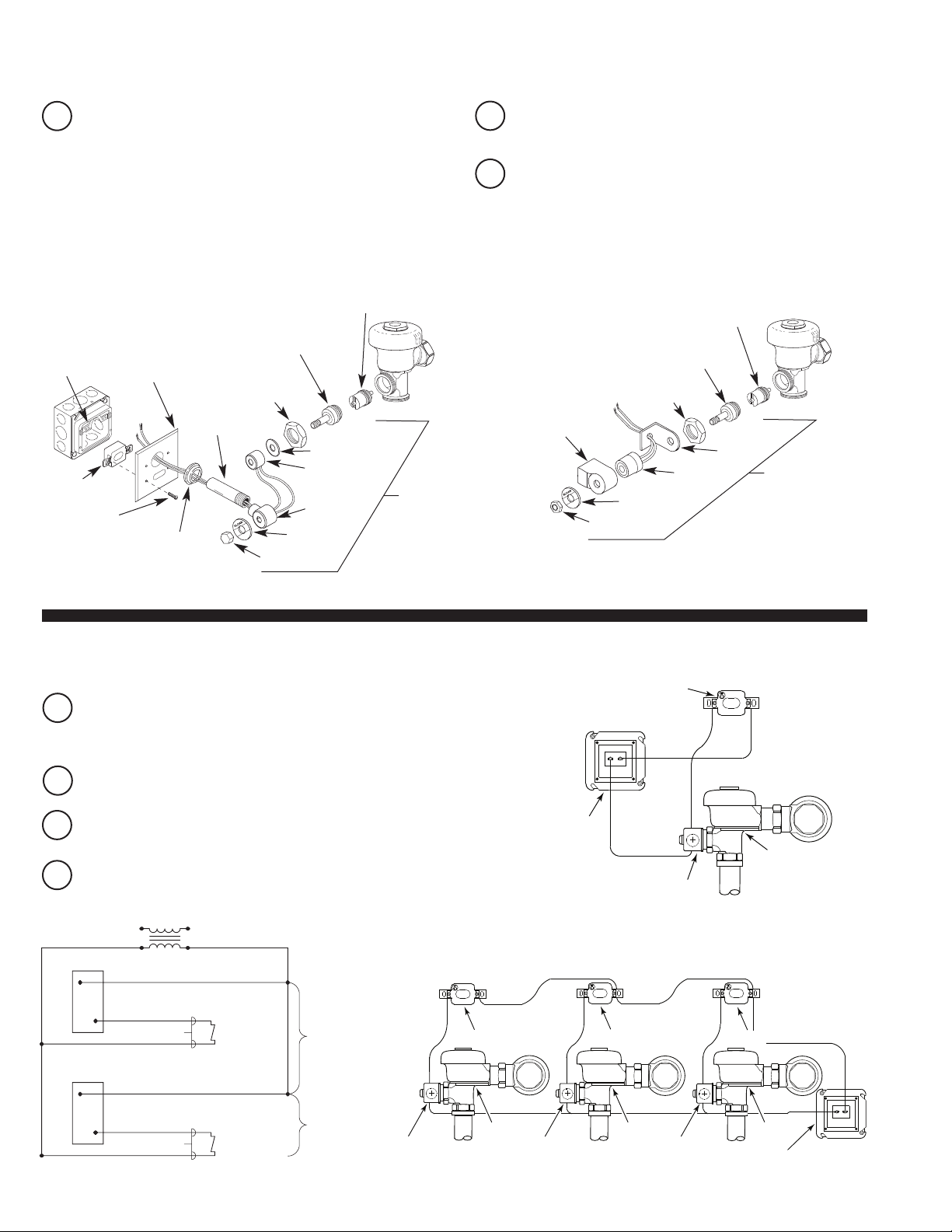
Connect Solenoid Operator
To ease installation, remove the Solenoid Operator from the
A
Flushometer; however, prior to removal, read and adhere to the
following precautions.
• When removing the Coil from the Solenoid Plunger Guide, do so
only with the power
OFF
. Failure to turn power off can result in
damage to the Sensor, Solenoid Coil and Transformer.
• When removing the Solenoid Operator from the Valve, take care
not to damage the O-ring seal on the Operator Assembly.
EXPOSED FLUSHOMETER CONCEALED FLUSHOMETER
CARTRIDGE ASSEMBLY
(EL-128-A)
SOLENOID SHAFT ASSEMBLY
YOKE
(EL-168-A)
SENSOR
(EL-1500)
SCREW
(EL-152)
(4 REQ’D)
Important:
COVER PLATE
(EL-151)
FLANGE
ASSEMBLY
(EL-431-A)
Do not remove coil from solenoid plunger guide unless power has been disconnected. Failure to do so may damage sensor, coil and transformer.
W/SOLENOID ADAPTER
(EL-163-A)
HANDLE
COUPLING (A-6)
TAIL
(F-15)
PLATE (EL-164)
COIL (EL-165-2)
SOLENOID
HOUSING
(EL-162-2)
FACE PLATE
(EL-102-2)
NUT (EL-101)
SOLENOID
OPERATOR
(EL-124-2)
Exposed models only
B
nd screw Tail into Solenoid Housing (EL-162-2).
a
Exposed models only
C
— Slide Coil wires through Tail (F-15)
— Slide Flange Assembly (EL-431-A)
and Cover Plate (EL-151) over Tail, respectively.
CARTRIDGE ASSEMBLY
(EL-128-A)
SOLENOID SHAFT ASSEMBLY
W/SOLENOID ADAPTER (EL-163-A)
HANDLE
SOLENOID
HOUSING
(EL-541-A)
COUPLING (A-6)
COIL
(EL-165-2)
FACE PLATE
(EL-102-2)
NUT (EL-166)
BASE PLATE
(EL-542)
SOLENOID
OPERATOR
(EL-138-2)
Electrical Hook-Up
6
120 VAC
24 VAC
OFF
to prevent damage to electrical
24 VAC COIL
UNIT #1
Be certain power is
A
components. Connect Sensor to Transformer and Solenoid coil
EXACTLY as shown.
Connect 24 volt source lead to terminal labeled “24 VAC IN” of
B
Sensor.
Connect solenoid lead to terminal labeled “TO VALVE” of Sensor.
C
Connect remaining solenoid lead to remaining 24 volt source lead.
D
WIRING
DIAGRAM
EL-1500 SENSOR
COIL WIRE
EL-1500 SENSOR
SENSOR
Wiring Diagram for One Flush Valve
SENSOR
TRANSFORMER
SOLENOID
Wiring Diagram for Multiple Flush Valves
SENSOR
VALVE
SENSOR
COIL WIRE
24 VAC COIL
UNIT #2
THRU #10
(IF USED)
SOLENOID
VALVE
SOLENOID SOLENOID
4
VALVE
VALVE
TRANSFORMER
Page 5
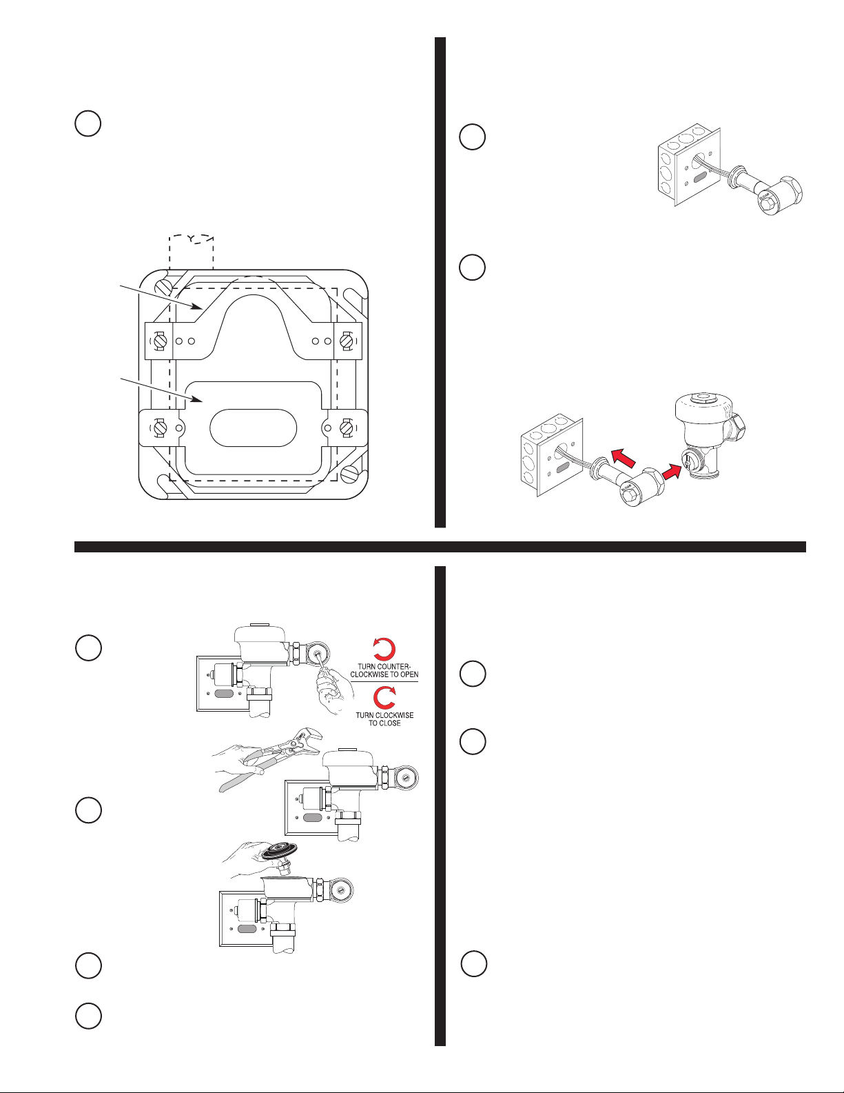
Install Sensor and Yoke
7
Install OPTIMA Sensor (EL-1500) into the 2-gang Electrical Box
A
using two (2) long screws provided. Ensure that Sensor Lens faces
outward and horizontally from finished wall. Mount Yoke
(EL-168-A) using two (2) long screws provided.
Install Sensor Cover Plate and
8
Secure Solenoid Housing and
Coil Assembly
Install Sensor Cover Plate
A
(EL-151, Exposed; EL-161,
Concealed) and secure with
Tamper-Proof Screws
(EL-152), provided.
YOKE
(EL-168-A)
SENSOR
(EL-1500)
9
Make sure Control
A
Stop is CLOSED.
Flush Out Supply Line
Models 180 ES-S and 186 ES-S
B
Solenoid Operator to Flushometer while aligning Tail Assembly to
Cover Plate. Wet O-Ring seal of Solenoid Operator with water to
lubricate. Secure Solenoid Operator to Flushometer by tightening
Solenoid Coupling. Slide Solenoid Flange Assembly (EL-431-A)
against Sensor Cover Plate (EL-151) and tighten Setscrew to
Tail (F-15).
Note:
Hex key wrench services Tamper-Proof Screws and
Setscrew. Tighten solenoid Nut (EL-101).
— Carefully install
Power and Start-up Mode
10
Note:
It is recommended that all electronic connections be tested with the
water supply OFF.
Turn Power ON. The self adaptive sensor automatically adapts to
A
the surrounding environment when 24 volt supply is activated. No
manual adjustments are required.
Remove Flushometer
B
Cover and lift out
Inside Parts Assembly.
Install Flushometer
Cover wrench tight.
Open Control Stop. Turn on water supply to flush line of any debris
C
or sediment.
Shut off Control Stop, remove Cover and reinstall Inside Parts
D
Assembly. Install Flushometer Cover wrench tight. Do Not open
Control Stop until Step 12.
Start-up mode will take approximately five (5) minutes to complete
B
its cycle and is important that no non-permanent target is present
at this time. A continuous red light visible in sensor window
indicates sensor is in the start-up mode. If the red light is flashing,
this indicates that the sensor is picking up a target. Unless this
target is a permanent fixture in the sensor’s environment (i.e., a
wall or stall door), it must be removed from the view of the sensor.
If this target is permanent, the sensor will adapt itself around this
target. In this case, the start-up mode may take up to ten (10)
minutes. When the start-up cycle is completed, no light is visible in
sensor window.
Note:
If 24 volt power supply is interrupted at any time for more than
fifteen (15) seconds, the start-up mode automatically repeats itself when
power is restored.
If indicator light flashes three (3) times slowly, three (3) times
C
rapidly and again three (3) times slowly and continually repeats
this signal, this indicates incorrect wiring or a short in the 24 volt
supply.
5
Page 6
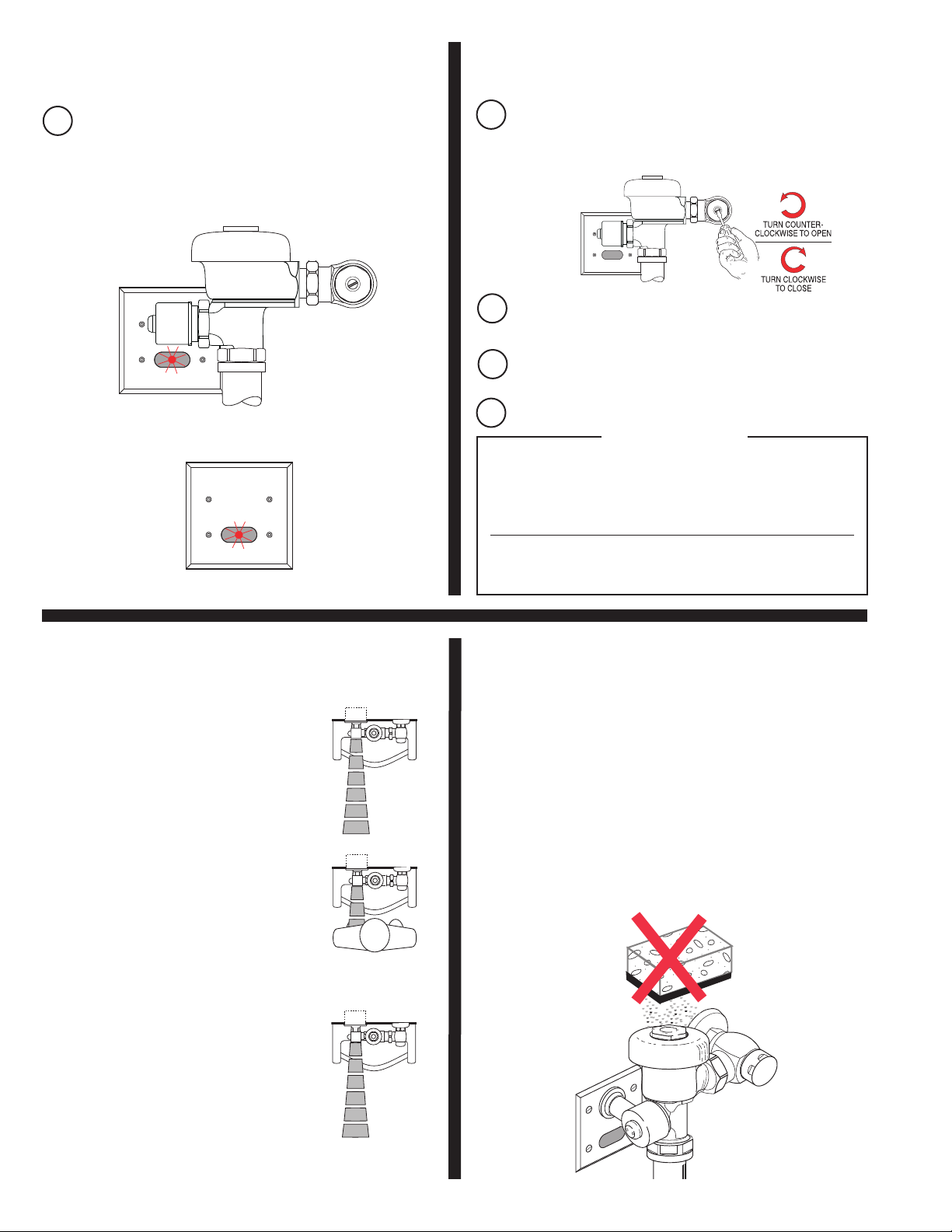
Detection/Activation
11
When an object is detected, a slowly flashing red light will appear
A
in the sensor window. After approximately eight (8) to ten (10)
seconds, the light will flash rapidly indicating sensor is armed and
ready to activate solenoid when the object leaves the detection
area. The solenoid will be activated within two (2) to four (4)
seconds after non-detection.
EXPOSED FLUSHOMETER
CONCEALED FLUSHOMETER
Turn Water on and Adjust
12
A
B
C
D
The Sloan®and Regal®Flushometer is engineered for quiet operation.
Excessive water flow creates noise, while too little water flow may not
plumbing fixture is cleansed after each flush without splashing water out
Never open Control Stop to where the flow from the valve exceeds the
flow capability of the fixture. In the event of a valve failure, the fixture
Control Stop
Adjust Control Stop to meet the flow rate required for proper
cleansing of the fixture. Open Control Stop COUNTERCLOCKWISE
1/2 turn from the closed position.
Exposed Model Shown
Activate Flushometer by placing hand in front of OPTIMA Sensor
Lens for ten (10) seconds and then moving it away.
Adjust Control Stop after each flush until the rate of flow delivered
properly cleanses the fixture.
Install Vandal Resistant Control Stop Cap onto Control Stop.
!!! IMPORTANT !!!
satisfy the needs of the fixture. Proper adjustment is made when
from the lip AND a quiet flushing cycle is achieved.
must be able to accommodate a continuous flow from the valve.
Operation
1.
A continuous, invisible light beam is emitted
from the OPTIMA Sensor.
2.
When a user enters the beam’s effective
range, 15 to 30 inches (381 mm to 762 mm),
the beam is reflected into the OPTIMA’s
scanning window and transformed into a low
voltage electrical signal that activates a tensecond time delay circuit. The time delay
circuit eliminates false operation from
passers-by in the rest room. Once the time
delay is completed, the output circuit is
alerted and continues in a “hold” mode for as
long as the user remains within the effective
range of the sensor.
3.
When the user steps away from the OPTIMA
Sensor, the loss of reflected light initiates an
electrical “one-time” signal that energizes the
Solenoid Operator, and activates the
Flushometer to flush the fixture. The circuit
then automatically resets and is ready for the
next user.
Care and Cleaning
DO NOT
clean Flushometers as they may dull the luster and attack the chrome or special
decorative finishes. Use ONLY soap and water, then wipe dry with clean cloth or
towel.
While cleaning the bathroom tile, the Flushometer should be protected from any
splattering of cleaner. Acids and cleaning fluids can discolor or remove chrome
plating.
use abrasive or chemical cleaners (including chlorine bleach) to
6
Page 7

TROUBLESHOOTING GUIDE
NOTE:
indicator light flashes
1. PROBLEM: Valve does not function (red light does not flash when user
Upon detection of the user, the red indicator light flashes
rapidly
steps in front of sensor).
AUSE: No power is being supplied to sensor.
C
SOLUTION: Ensure that the main power is turned “ON.” Check
Transformer, leads and connections. Repair or replace as
necessary.
and the Sensor initiates the flush sequence. Then the indicator light
slowly
CAUSE: EL-1500 Sensor is not operating.
SOLUTION: Replace EL-1500 Sensor.
2. PROBLEM: Valve does not function (red light flashes when user steps in
front of Sensor).
INDICATOR: Red light stops flashing when user steps away and valve
makes a “clicking” sound but does not flush.
CAUSE: No water is being supplied to the valve.
SOLUTION: Make certain that water supply is turned “ON” and the
Control Stop is open.
CAUSE: EL-128-A Cartridge is fouled or jammed.
SOLUTION: Turn electronic power to valve “OFF” (failure to do so could
result in damage to the solenoid coil). Remove the solenoid
operator from the valve and remove the
EL-128-A cartridge. Clean and/or repair as necessary.
INDICATOR: The red light stops flashing when user steps away but the
valve does NOT make a “clicking” sound and does NOT flush.
CAUSE: EL-163-A Solenoid Shaft assembly is fouled or jammed.
SOLUTION: Turn electronic power to valve “OFF” (failure to do so could
result in damage to the Solenoid Coil). Remove
EL-101 or EL-166 nut from the Solenoid Operator. Remove
the coil from the solenoid operator. Use a spanner wrench or
pliers to remove the EL-163-A Solenoid Shaft assembly from
valve. Clean and/or replace as necessary. Be sure to replace
Plunger Spring when reassembling Solenoid Shaft Assembly.
INDICATOR: The red light flashes three (3) short flashes, three (3) long
flashes then three (3) short flashes (“S-O-S”) and continues
to repeat this cycle even when user steps out of the sensor’s
detection range.
CAUSE: EL-1500 Sensor wiring connections are incorrect.
SOLUTION: Rewire Sensor to valve. One solenoid lead connects to the
“TO VALVE” connection on Sensor. One transformer lead
connects to the “24 VAC IN” connection on Sensor. Second
solenoid lead and second transformer lead connect together.
CAUSE: Wiring to Sensor is ground shorted.
SOLUTION: Find short in wiring circuit and correct.
CAUSE: EL-165-2 Solenoid Coil is burnt out or Coil is not connected
to Solenoid Plunger shaft.
SOLUTION: Reinstall or replace Coil as necessary.
for a period of eight seconds. When the user leaves the detection range, the
stops
flashing and the valve flushes.
3. PROBLEM: Volume of water is insufficient to adequately siphon fixture.
CAUSE: Control Stop is not open wide enough.
SOLUTION: Adjust Control Stop for desired water delivery.
CAUSE: Low Consumption unit is installed on Water Saver or
Conventional fixture.
SOLUTION: Replace Diaphragm component parts of valve with kit that
corresponds to appropriate flush volume of fixture.
CAUSE: Inadequate water volume or pressure available from supply.
SOLUTION: Increase pressure or supply (flow rate) to the valve. Consult
factory for assistance.
4. PROBLEM: Length of flush is too long (long flushing) or valve fails to shut
off.
CAUSE: Water Saver Valve is installed on Low Consumption fixture.
SOLUTION: Replace Diaphragm component parts of valve with kit that
corresponds to appropriate flush volume of fixture.
CAUSE: Relief valve in Diaphragm is not seated properly or bypass
hole in Diaphragm is clogged.
SOLUTION: Disassemble inside Diaphragm component parts and wash
5. PROBLEM: Water splashes from fixture.
parts thoroughly. Replace worn parts if necessary.
CAUSE: Supply flow rate is more than necessary.
SOLUTION: Adjust Control Stop to meet flow rate required for proper
cleansing of the fixture.
CAUSE: Closet valve is installed on urinal fixture.
SOLUTION: Replace closet Diaphragm component parts with proper urinal
kit (Inside Diaphragm Assembly or Inside Parts Kit).
If further assistance is required, please contact the Sloan Valve Company
Installation Engineering Department at:
1-888-SLOAN-14 (1-888-756-2614)
!!! IMPORTANT — Control Stop Setting !!!
Never open Control Stop to where the flow from the valve exceeds the flow
capability of the fixture. In the event of a valve failure, the fixture must be
able to accommodate a continuous flow from the valve.
7
Page 8
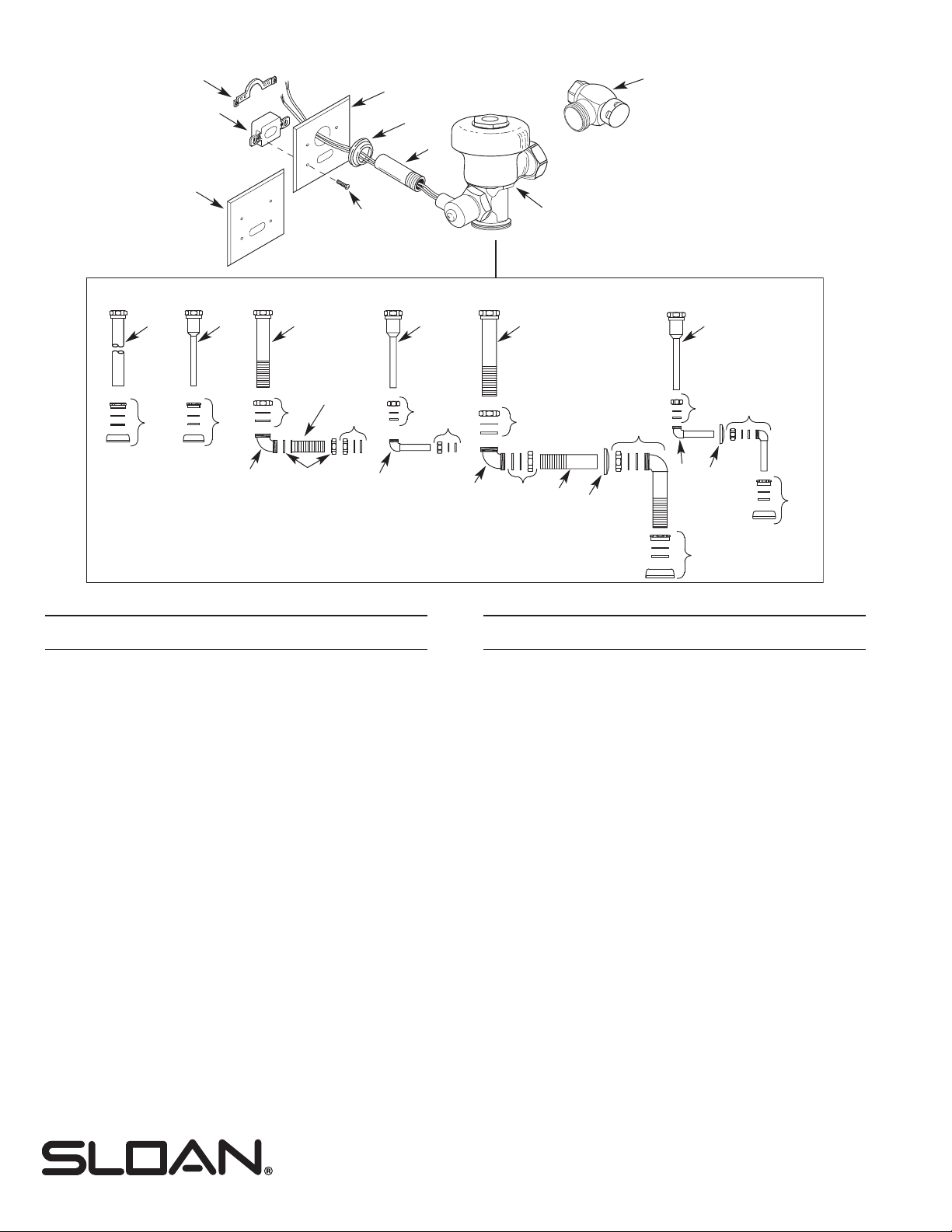
PARTS LIST
21B
23
24
21A
20
19
2
22
180 ES-S
186 ES-S 190 ES-S 195 ES-S 192 ES-S 197 ES-S
3A
4A
3B
4B
7
3C 3D 3E 3D
10
8
11
9
5
Item Part Description
No. No.
1‡Solenoid Operated Valve Assembly
2 H-700-A ‡ 1” (25 mm) Bak-Chek
H-700-A ‡ 3/4” (20 mm) Bak-Chek
®
Control Stop
®
Control Stop
3A V-600-AA 1-1/4" (32 mm) x 9" (229 mm) Vacuum Breaker Assembly
CP (Model 180 ES-S)
3B V-600-AA 3/4" (20 mm) x 9" (229 mm) Vacuum Breaker Assembly CP
(Model 186 ES-S)
3C V-500-AA 1-1/2" (38 mm) x 11-1/2" (292 mm) Vacuum Breaker
Assembly RB (Model 190 ES-S)
3D V-500-AA 3/4" (19 mm) x 10-1/2" (267 mm) Vacuum Breaker
Assembly RB (Models 195 ES-S and 197 ES-S)
3E V-500-AA 1-1/2" (38 mm) x 7-1/2" (191 mm) Vacuum Breaker
Assembly RB (Model 192 ES-S)
4A F-5-A 1-1/4" (32 mm) Spud Coupling Assembly
(Model 180 ES-S)
4B F-5-A 3/4" (19 mm) Spud Coupling Assembly (Model 186 ES-S)
5 F-15-A ELL with 3/4" (19 mm) Tail
(Models 195 ES-S and 197 ES-S)
6 F-2-AW 3/4" (19 mm) Slip Joint Coupling
(Models 195 ES-S and 197 ES-S)
7 F-21 Double Slip Elbow (Models 190 ES-S and 192 ES-S)
8 F-2A 1-1/2" (38 mm) Slip Joint Coupling (Model 190 ES-S)
9 F-2A Coupling with S-21 Gasket
10 F-110 1-1/4" (32 mm) O.D. Outlet
11 F-2-A-U 1-1/4" (32 mm) Slip Joint Coupling
12 F-2-AA 1-1/2" (38 mm) Slip Joint Coupling (Set of Two)
(Model 192 ES-S)
13 F-102 1-1/2" Outlet Tube CP
14 F-7 Flange
15 F-25-A 1-1/4" Elbow Assembly
16 F-15-A ELL with 3/4" Tail CP (Model 197 ES-S)
1
16
6
6
7
12
12
13
14
15
6
5
14
18
17
Item Part Description
No. No.
17 F-5-A 1-1/4" Spud Coupling Assembly CP
18 F-5-A 3/4" Spud Coupling Assembly CP
19 F-15 Tail Assembly
20 EL-431-A Flange Assembly
21A EL-151 Cover Plate (Models 180 ES-S and 186 ES-S)
21B EL-161 Cover Plate (Models 190 ES-S, 192 ES-S, 195 ES-S
and 197 ES-S)
22 EL-152 Screw (4 Required)
23 EL-168-A Yoke Assembly
24 EL-1500 Urinal Sensor
‡ Part number varies with valve model variation; consult
factory.
INSTALLATION TEMPLATE
For Models 180/186 ES-S:
Code # 0816156
The information contained in this document is subject to
change without notice.
Sloan and Regal
Detailed Parts Breakdown
For a detailed parts breakdown of Regal Optima ES-S Flushometers, see
Maintenance Guide 0816510.
For a detailed parts breakdown of Sloan Optima ES-S Flushometers, see
Maintenance Guide 0816725.
Copyright © 201
6 SLOAN VALVE COMPANY
Phone: +1.800.982.5839 or +1.847.671.4300 • Fax: +1.800.447.8329 or +1.847.671.4380
SLOAN VALVE COMPANY • 10500 Seymour Avenue • Franklin Park, IL 60131
www.sloan.com
-16
06
 Loading...