

Page 1
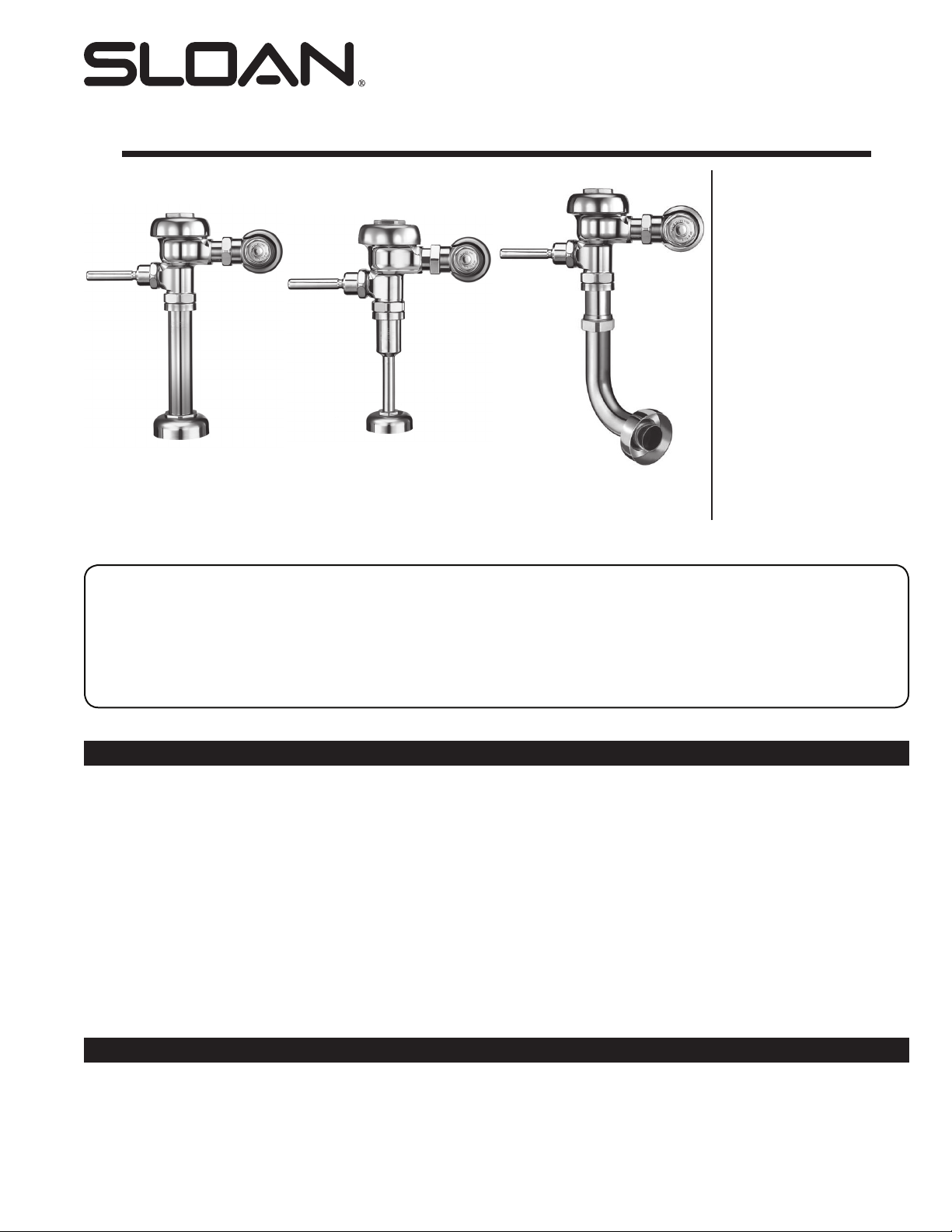
INSTALLATION INSTRUCTIONS FOR EXPOSED REGAL® XL
WATER CLOSET AND URINAL FLUSHOMETERS
Closet Flushometer
1½” (38 mm) Top Spud
MODELS 110/111,
113, 115 & 116
Closet Flushometer
1½” (38 mm) Back Spud
MODEL 120 & 122
Service Sink Flushometer
1½” (38 mm) Top Spud
MODEL 117
Urinal Flushometer
1¼” (32 mm) Top Spud
MODEL 180
Urinal Flushometer
¾” (19 mm) Top Spud
MODEL 186
Squat Toilet Flushometer
1½” (38 mm) Back Spud
MODEL 137
Code No. 0816312
Rev. 2 (04/14)
LIMITED WARRANTY
Unless otherwise noted, Sloan Valve Company warrants this product, manufactured and sold for commercial or industrial uses, to be free from defects in material
and workmanship for a period of three (3) years (one (1) year for special finishes, SF faucets, PWT electronics and 30 days for PWT software) from date of first
purchase. During this period, Sloan Valve Company will, at its option, repair, replace, or refund the purchase price of any product which fails to conform with this
warranty under normal use and service. This shall be the sole and exclusive remedy under this warranty. Products must be returned to Sloan Valve Company, at
customer’s cost. No claims will be allowed for labor, transportation or other costs. This warranty extends only to persons or organizations who purchase Sloan Valve
Company’s products directly from Sloan Valve Company for purpose of resale. This warranty does not cover the life of the batteries.
THERE ARE NO WARRANTIES WHICH EXTEND BEYOND THE DESCRIPTION ON THE FACE HEREOF. IN NO EVENT IS SLOAN VALVE COMPANY
RESPONSIBLE FOR ANY CONSEQUENTIAL DAMAGES OF ANY MEASURE WHATSOEVER.
PRIOR TO INSTALLATION
Before you install the Regal XL flushometer, be sure the items listed below
are installed. Also, refer to the rough-in diagrams on the next page.
• Closet or urinal fixture
• Drain line
• Water supply line
IMPORTANT:
• INSTALL ALL PLUMBING IN ACCORDANCE WITH
APPLICABLE CODES AND REGULATIONS.
• WATER SUPPLY LINES MUST BE SIZED TO PROVIDE
AN ADEQUATE VOLUME OF WATER FOR EACH
FIXTURE.
• FLUSH ALL WATER LINES PRIOR TO MAKING
CONNECTIONS.
Sloan’s flushometers are designed to operate with 10 to 100 psi (69 to 689
kPa) of water pressure. THE MINIMUM PRESSURE REQUIRED
TO THE VALVE IS DETERMINED BY THE TYPE OF
FIXTURE SELECTED. Consult fixture manufacturer for minimum
pressure requirements. Most Low Consumption water closets (1.6 gpf/6.0
Lpf) require a minimum flowing pressure of 25 psi (172 kPa).
TOOLS REQUIRED FOR INSTALLATION
• Straight blade screwdriver
• Sloan A-50 Super-Wrench™, Sloan A-109 Plier Wrench or smooth jawed spud wrench
Page 2
†
†
†
†
†
†
†
†
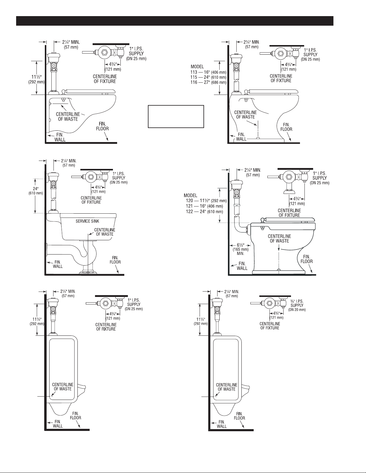
VALVE ROUGH-INS
MODELS 110/111
MODELS 113, 115 & 116
†
NOTE: Water Closet
Valves with “-2.4”
Model Designation
MODEL 117 MODELS 120/122
deliver 2.4 gpf (9.0 Lpf)
†
†
†
MODEL 180 MODEL 186
†
NOTE: Model 180
requires 1” I.P.S.
(DN 25 mm) Supply
† 1” Control Stop is available with Whitworth Thread
IMPORTANT NOTES:
• When mounted on an ADA accessible bowl, the rough-in to the supply inlet should be no higher than 37½” or the handle will exceed maximum height allowances under ADA guidelines.
• New ADAAG Guidelines allow for Split or Offset Grab Bars, check with local authorities or reference section 604.5.2 of ADAAG.
2
Page 3
WITH THE EXCEPTION OF CONTROL STOP INLET, DO
!!! IMPORTANT !!!
NOT USE PIPE SEALANT OR PLUMBING GREASE ON ANY
VALVE COMPONENT OR COUPLING!
!!! IMPORTANT !!!
PROTECT THE FINISH OF SLOAN’S FLUSHOMETERS —
DO NOT USE TOOTHED TOOLS TO INSTALL OR
SERVICE THESE VALVES. USE A SLOAN A-50 Super-
Wrench™, Sloan A-109 PLIER WRENCH OR SMOOTH
JAWED SPUD WRENCH TO SECURE ALL COUPLINGS.
SEE “CARE AND CLEANING” SECTION.
!!! IMPORTANT !!!
THIS PRODUCT CONTAINS MECHANICAL AND/OR
ELECTRICAL COMPONENTS THAT ARE SUBJECT TO
NORMAL WEAR. THESE COMPONENTS SHOULD BE
CHECKED ON A REGULAR BASIS AND REPLACED AS
NEEDED TO MAINTAIN THE VALVE’S PERFORMANCE.
NEVER OPEN CONTROL STOP TO WHERE THE FLOW
FROM THE VALVE EXCEEDS THE FLOW CAPABILITY
OF THE FIXTURE. IN THE EVENT OF A VALVE FAILURE,
THE FIXTURE MUST BE ABLE TO ACCOMMODATE A
CONTINUOUS FLOW FROM THE VALVE.
LAWS AND REGULATIONS PROHIBIT THE USE
OF HIGHER FLUSHING VOLUMES THAN LISTED ON
Please take the time to read this manual to ensure proper product installation
and longevity. Also, please visit our website to download our most recent
If you have questions about how to install your Flushometer, consult your local
Sloan Representative or call Sloan Technical Support at:
1-888-SLOAN-14 (1-888-756-2614)
!!! IMPORTANT !!!
!!! IMPORTANT !!!
FIXTURE OR FLUSHOMETER.
documentation for this product.
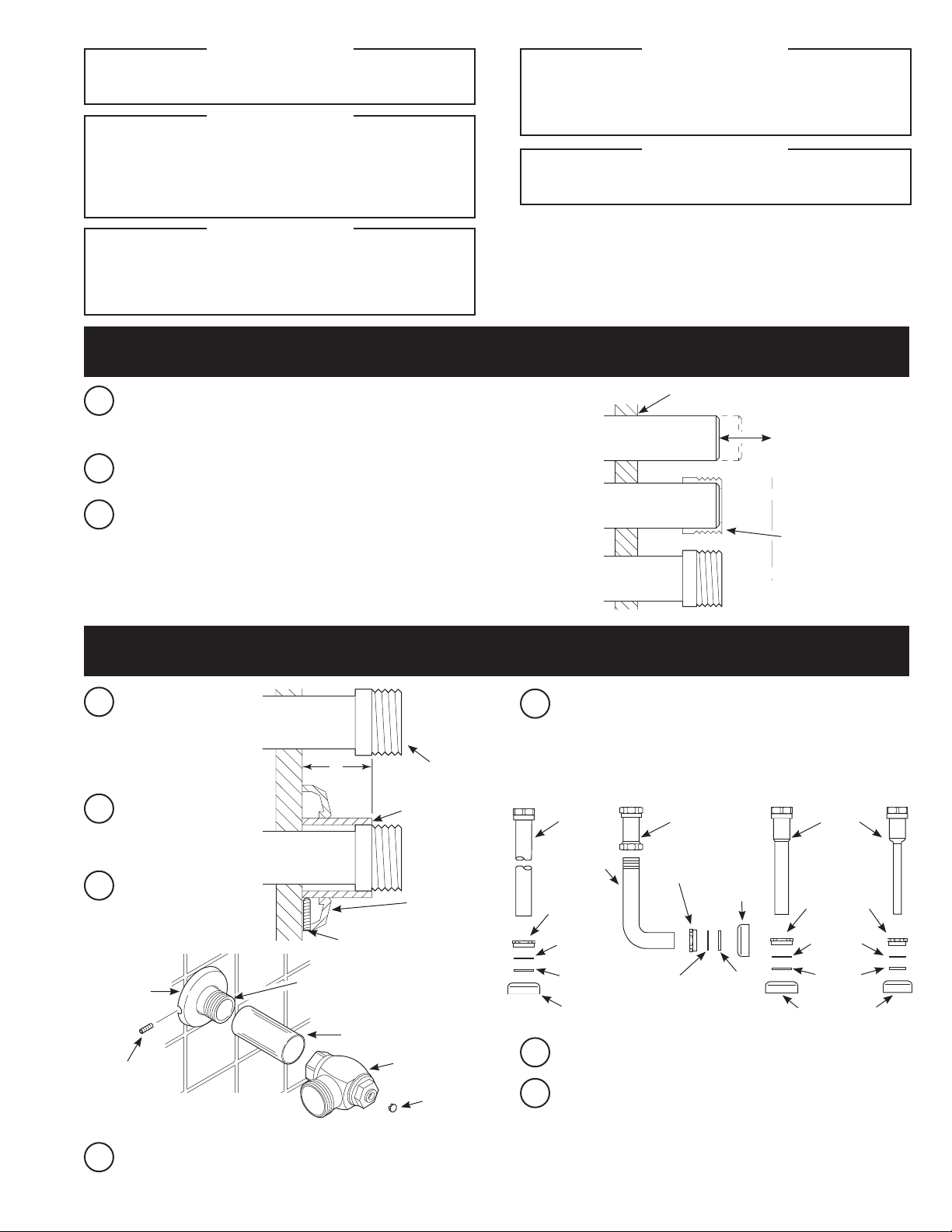
1 - INSTALL SWEAT SOLDER ADAPTER (ONLY IF YOUR SUPPLY PIPE DOES
NOT HAVE A MALE THREAD)
Measure from finished wall to C/L of Fixture Spud. Cut pipe 1¼”
A
(32 mm) shorter than this measurement. Chamfer O.D. and I.D. of
water supply pipe.
Slide Threaded Adapter fully onto pipe.
B
WATER SUPPLY PIPE
FINISHED WALL
1-1/4”
(32 mm)
Sweat solder the Adapter to pipe.
C
SWEAT
SOLDER
ADAPTER
C/L OF
FIXTURE
SPUD
2 - INSTALL COVER TUBE, WALL FLANGE AND CONTROL STOP TO
SUPPLY PIPE AND INSTALL VACUUM BREAKER FLUSH CONNECTION
Measure from finished wall
A
to first thread of adapter
or threaded supply pipe
(dimension “X”). Cut cover
tube to this length.
Slide cover tube over pipe.
B
Slide wall flange over
cover tube until against
wall.
Thread Control Stop
C
onto pipe. Tighten with a
wrench making sure outlet
is positioned as required.
SUPPLY
FLANGE
SETSCREW
† COVER TUBE AND CAST SUPPLY FLANGE
WITH SETSCREW ARE AVAILABLE IN
“YBYC” SWEAT SOLDER KIT.
†
WATER
SUPPLY PIPE
X
SETSCREW
IRON PIPE NIPPLE OR
COPPER PIPE WITH
SWEAT SOLDER ADAPTER
SWEAT SOLDER
ADAPTER
COVER TUBE
O
T
P
S
S
E
I
R
E
S
0
0
7
-
H
COVER TUBE
WALL
FLANGE
†
BAK-CHEK
®
CONTROL STOP
PLUG
E
MODELS
110/111,
113, 115,
116 & 117
ELBOW FLUSH
CONNECTION
SPUD COUPLING
F
G
Slide spud coupling, nylon slip gasket, rubber gasket and spud
flange over vacuum breaker tube.
VACUUM
BREAKER
TUBE
NYLON SLIP
GASKET
RUBBER
GASKET
SPUD FLANGE
MODELS
120 & 122
VACUUM
BREAKER
SPUD COUPLING
SPUD FLANGE
NYLON
SLIP
GASKET
RUBBER
GASKET
MODEL
180
VACUUM
BREAKER
TUBE
SPUD COUPLING
NYLON SLIP
GASKET
RUBBER
GASKET
SPUD FLANGE
Insert Tube into Fixture Spud.
Hand tighten Spud Coupling onto Fixture Spud.
MODEL
186
Tighten setscrew with a 1/16” hex wrench. DO NOT install
D
vandal resistant plug at this time.
3
Page 4
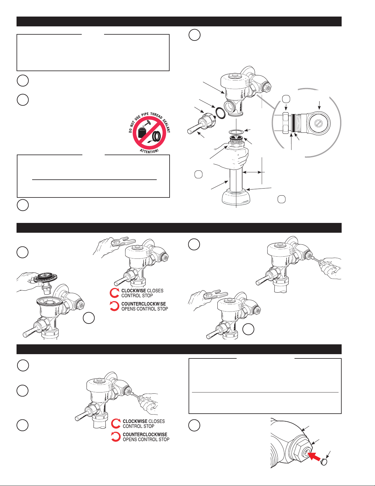
3 - INSTALL FLUSHOMETER AND HANDLE ASSEMBLY
NOTE
For high efciency urinal ushometers (0.5, 0.25 and 0.125 gpf),
it is necessary to rst insert the ow control component into the
tailpiece assembly. See the H1015A ow control kit and separate
instructions for details on how to install.
Lubricate tailpiece O-ring with water. Insert Adjustable Tailpiece
A
into Control Stop. Tighten Tailpiece Coupling by hand.
Align Flushometer directly above the Vacuum Breaker Flush
B
Connection by sliding the Flushometer Body IN or OUT as needed.
Tighten Vacuum Breaker Coupling by hand.
NOTE
Maximum adjustment of the Sloan Adjustable Tailpiece is 1/2”
(13 mm) IN or OUT from the standard 4-3/4” (121 mm) (centerline of
Flushometer to centerline of Control Stop).
If roughing-in measurement exceeds 5-1/4” (133 mm), consult
factory for longer tailpiece.
Align Flushometer Body. Using a wrench, securely tighten
C
couplings in the order given: (1) Tailpiece Coupling, (2) Vacuum
Breaker Coupling and (3) Spud Coupling.
FLUSHOMETER
A-31 GASKET
HANDLE
COUPLING
CONNECTION
Install the red A-31 Handle Gasket on the Handle Assembly. Insert
D
the ADA Handle Assembly (B-73-A) into the Handle opening in the
Flushometer Body. Securely tighten the Handle coupling with a
wrench.
BODY
HANDLE
ASSEMBLY
VACUUM
BREAKER
COUPLING
2
VACUUM
BREAKER
FLUSH
C/L
SUPPLY
G-44
FRICTION
RING
VACUUM
BREAKER
REPAIR KIT
C/L
FIXTURE
TAILPIECE
COUPLING
4-3/4”
(121 mm)
±1/2”
(13 mm)
SPUD
COUPLING
1
CONTROL
O-RING
ADJUSTABLE
TAILPIECE
3
STOP
4 - FLUSH OUT SUPPLY LINE
Reinstall Outside and
C
Make sure Control Stop
A
is CLOSED and remove
Flushometer Outer Cover.
Inside Cover wrench
tight. Open Control Stop
to flush supply line. Close
Control Stop and remove
Outside and Inside Cover.
Remove Inside Cover and lift
B
out Inside Parts Assembly.
5 - ADJUST CONTROL STOP AND INSTALL PLUG
Open control stop COUNTERCLOCKWISE one FULL turn from
A
closed position.
Activate flushometer.
B
Adjust control stop after
C
each flush until the rate
of flow delivered properly
cleanses the fixture.
Sloan’s flushometers are engineered for quiet operation.
Excessive water flow creates noise, while too little water flow
may not satisfy the needs of the fixture. Proper adjustment is
made when the plumbing fixture is cleansed after each flush
without splashing water out from the lip AND a quiet flushing
Never open Control Stop to where the flow from the valve
exceeds the flow capability of the fixture. In the event of a
valve failure, the fixture must be able to accommodate a
Install plug into the control
D
stop by pressing into bonnet.
Reinstall Inside Parts Assembly, Inside
D
Cover and Outside Cover wrench tight.
!!! IMPORTANT !!!
cycle is achieved.
continuous flow from the valve.
®
BAK CHEK
CONTROL STOP
I
R
E
S
0
0
7
-
H
BONNET
O
T
P
S
S
E
PLUG
4
Page 5

CARE AND CLEANING
DO NOT USE abrasive or chemical cleaners (including chlorine bleach) to
clean Flushometers that may dull the luster and attack the chrome or special
decorative finishes. Use ONLY mild soap and water, then wipe dry with
clean cloth or towel.
While cleaning the bathroom tile, protect the Flushometer from any splattering
of cleaner. Acids and cleaning fluids will discolor or remove chrome plating.
TROUBLESHOOTING GUIDE
I. Flushometer does not function (no flush).
A. Control stop or main valve is closed. Open control stop or main valve.
B. Handle assembly is damaged. Replace handle (B-32-A or B-73-A) or
install handle repair kit (B-50-A).
C. Relief valve is damaged. Replace inside parts kit.
2. Volume of water is not sufficient to siphon fixture.
A. Control stop is not open wide enough. Adjust control stop for desired
delivery of water volume.
B. Urinal flushometer parts inside a closet flushometer. Replace inside urinal
parts with proper closet flushometer parts.
C. Low consumption flushometer installed on a non-low consumption fixture.
Replace A-41-A inside parts kit with A-38-A water saver kit.
D. Water saver kit installed in old, non-water saver bowl. Position refill head
A-170 so that SIDE 1 is in the UP position.
E. Inadequate volume or pressure at supply.
• If no gauges are available to properly measure supply pressure or
volume of water at the flushometer, then remove the relief valve from
the inside parts kit, reassemble the flushometer and open the control
stop. If the fixture siphons, more water volume is required. If a 3.5
gpf inside parts kit is installed in the flushometer, then first flip the
refill head (under the diaphragm) to obtain a 4.5 gpf volume. If this
volume is still inadequate, remove the flow ring from the guide to
obtain a 6.5 gpf kit. If additional flow is still required, try a low pressure
guide kit A-175-A (#0301104).
REGULATIONS PROHIBIT THE USE OF HIGHER FLUSHING
VOLUMES THAN LISTED ON FIXTURE OR FLUSHOMETER.
IMPORTANT — LAWS AND
• If fixture does not siphon or if a low consumption fixture is installed,
or if the above steps do not prove satisfactory, steps must be taken to
increase the pressure and/or supply.
3. Flushometer closes off immediately.
A. Damaged diaphragm. Replace inside parts kit to correct problem.
B. Enlarged by-pass orifice from corrosion or damage. Install inside parts kit
to correct problem and update flushometer.
4. Length of flush is too short (short flush).
A. Diaphragm assembly and guide assembly are not hand-tight. Screw the
two assemblies hand-tight.
B. Enlarged by-pass orifice from corrosion or damage. Install NEW Inside
parts kit to correct problem and update flushometer.
C. A-19-AU (Black) urinal relief valve in closet flushometer. Replace relief
valve with A-19-AC (White) closet relief valve.
D. A-41-A low consumption kit installed in non-low consumption fixture.
Replace with proper Inside Parts Kit.
E. Handle assembly is damaged. Replace handle (B-32-A or B-73-A) or
install handle repair kit (B-50-A).
5. Length of flush is too long (long flushing) or fails to close off.
A. Relief valve (A-19-A) is not seating properly or by-pass orifice is clogged
because of foreign material, or by-pass orifice is closed by an invisible
gelatinous film from “over-treated” water. Disassemble the working parts
and wash thoroughly.
NOTE: SIZE OF THE ORIFICE IN THE BY-PASS IS OF
UTMOST IMPORTANCE FOR THE PROPER METERING
OF WATER INTO THE UPPER CHAMBER OF THE
FLUSHOMETER. DO NOT ENLARGE OR DAMAGE THIS
ORIFICE. REPLACE INSIDE KIT IF CLEANING DOES NOT
CORRECT PROBLEM.
B. Line pressure has dropped and is not sufficient to force Relief Valve to
seat. Shut off all control stops until pressure has been restored, then
open them again.
C. A-19-AC (White) closet Relief Valve has been used in a 1 or 1½ gpf
Urinal. Replace with A-19-AU (Black) Relief Valve.
D. Inside cover is cracked or damaged. Replace the Inside Cover (A-71).
6. Chattering noise is heard during flush.
A. Inside Cover is damaged. Replace Inside Cover (A-71).
B. A-156-A Segment diaphragm has been installed upside-down. Reposition
the Segment diaphragm properly (see markings on the Diaphragm).
7. Handle Leaks.
A. B-39 Handle Seal is worn or damaged. Install new B-39 Seal.
NOTE: The B-39 Seal will easily slide onto the B-40 Bushing when wet.
B. Handle gasket has been omitted. Install Handle gasket (A-31) or Sloan
handle repair kit (B-50-A).
C. Valve handle bushing is worn. Replace handle repair kit (B-50-A).
When further assistance is required, please contact
Sloan Technical Support at:
1-888-SLOAN-14 (1-888-756-2614)
or visit us online at:
www.sloanvalve.com
5
Page 6
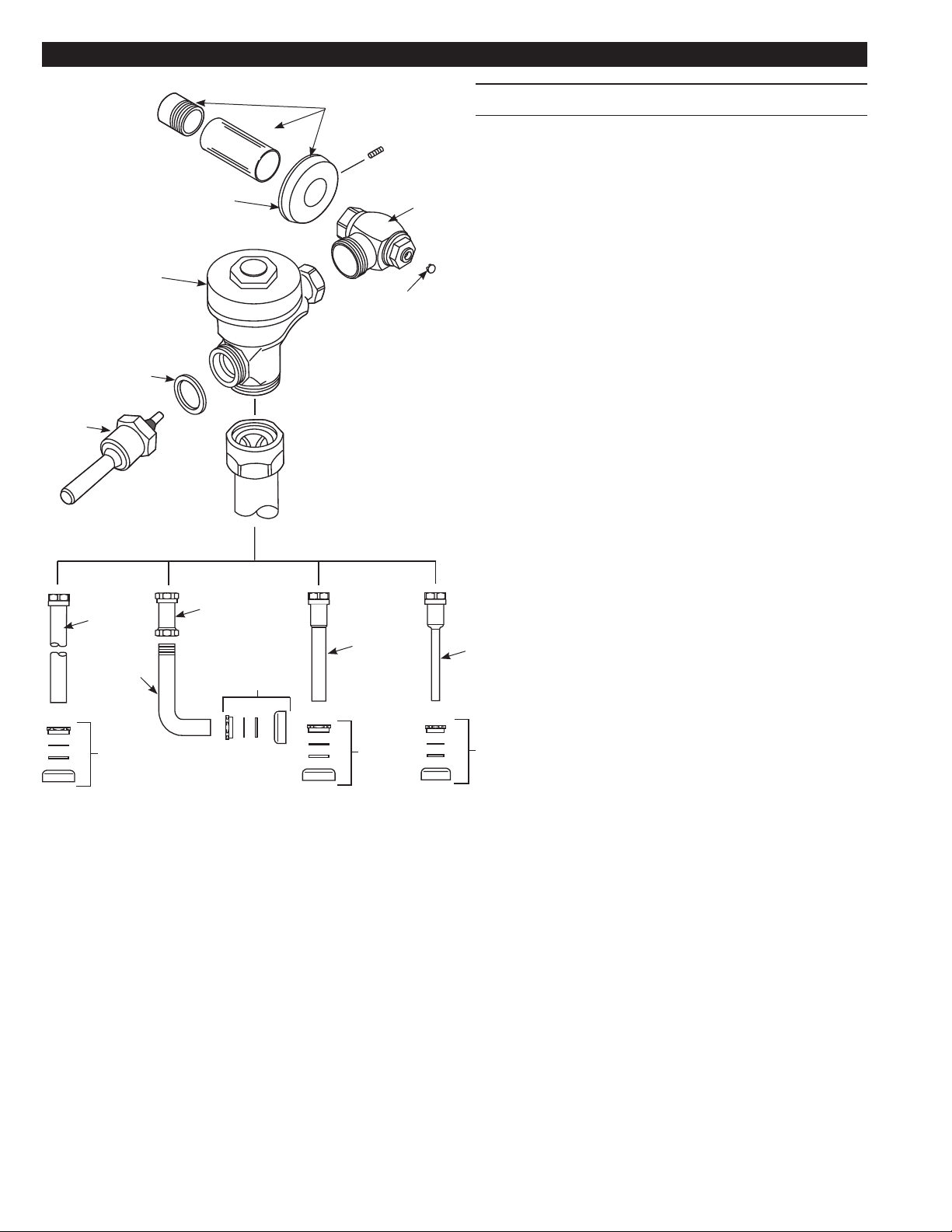
PARTS LIST
2A
2B
8
No. No.
1 † Valve Assembly
2A B-73-A ADA Compliant Handle Assembly
Item Part Description
2B A-31 Handle Gasket
3A H-790-A Bak-Chek
7
3A
3B H-528 Control Stop Bonnet Plug
4A V-500-AA 1½” (38 mm) x 9” (229 mm) Vacuum Breaker Assembly ‡
®
Control Stop
4B V-500-AA 1¼” (32 mm) x 9” (229 mm) Vacuum Breaker Assembly
O
T
S
P
S
E
I
R
E
S
0
0
7
-
H
1
3B
4C V-500-AA ¾” (19 mm) x 9” (229 mm) Vacuum Breaker Assembly
4D V-500-A Vacuum Breaker Assembly
5 F-109 1½” (38 mm) Elbow Flush Connection ‡
6A F-56-A 1½” (38 mm) Spud Coupling Assembly
6B F-57-A 1¼” (32 mm) Spud Coupling Assembly
6C F-58-A ¾” (19 mm) Spud Coupling Assembly
7 F-7 Supply Flange (Supplied when Valve is Not Ordered with
Sweat Solder Kit)
8 H-633-AA 1” (25 mm) Sweat Solder Kit and Cast Wall Flange
with Setscrew
H-636-AA ¾” (19 mm) Sweat Solder Kit and Cast Wall Flange
with Setscrew
† Part number varies with valve model variation; consult factory
‡ Length varies with valve model variation; consult factory
4A
6A
4D
4B
5
6A
4C
6B 6C
NOTE: The information contained in this document is subject to change without notice.
SLOAN • 10500 SEYMOUR AVENUE • FRANKLIN PARK, IL 60131
© 2014 SLOAN VALVE COMPANY Code No: 0816312 – Rev. 2 (04/14)
Ph: 1-800-982-5839 or 1-847-671-4300 • Fax: 1-800-447-8329 or 1-847-671-4380 • www.sloanvalve.com
 Loading...