

Page 1

30 cc Super Chipmunk
Congratulations on your purchase of this excellent almost-ready-to-fly
RIC model! This ARF adopts the latest design features and emphasizes
high performance
professional engineers a nd built by skilled craftsmen.
, light weight and fun. The plane is designed by
Assembly Manual
Page 2

Specifications:
Wing Span: 80” (2030mm)
Length(Including Spinner): 69” (1750mm)
Wing Area: 935 in² (60.4 dm²)
Flying Weight: 11 to 13 lbs(5-5.5kg)
Engine: .91-1.20(2C) 1.10-1.40 (4C) 20 - 35cc Gas
Radio: 4+ Channels
Servos : 6 servos required 80 oz/in
FEATURES
1. Latest Structure
2. Light weight construction and high structural strength
3. Super Quality
4. Complete with accessories
5. Easy installation
6. Low wing loading
7. Anodized 6061 T-6 wheels
8. Advanced PU wheels
A QUICK WORD ABOUT SAFETY AND RADIO CONTROL FLYING MODELS
With radio control aircraft, like any hobby or sport, there are certain risks. The operator
of these models is responsible for these risks. If misused or abused, you may cause serious
bodily injury and/or damage to property. With this in mind, you will want to be certain that you
build your model carefully and correctly. If you are not an experienced flier, have your work
checked by an experienced pilot and ask for help in learning to fly the model safely. This
model aircraft is not a toy and must be oper at ed and flown in a safe manner at all times.
Always perform a pre-flight check of the model which includes proper movements of all
control surfaces, proper function of the radio gear, structural integrity, and radio range.
Models are not insurable but operators are. You can obtain coverage through
Page 3

membership in the Academy of Model Aeronautics (AMA). For an AMA information package
• 20-35cc gas engine
Required engine and exhaust mounting
• Covering iron and heat gun
call 1-800-435-9262, ex t. 292 or visit the AMA website at "www.modelaircraft .org".
By the act of using the final assembled model, the purchaser/operator accepts all
resulting liability.
Items Required to Complete This Model:
• Appropriate propeller for your engine
•
hardware
• Batteries for ignition and radio system
• Appropriate HD switches
• Receiver of your choice
• Appropriate HD extensions
• 5-6 good quality servos (90oz/in)
Note: As with all kits, it's a good idea to read all the instructions and study the parts before you
begin construction. Handle the parts of this kit with care so you do not damage any of the
structure or covering. Inspect all the parts for any shipping damage and report any issues to
Slipstream dealers as soon as you can. Make sure you have a flat and sturdy workbench and
follow all safety advice for the tools and adhesi ves you plan to use.
AIRCRAFT COVERING:
1. With all ARFs, varying temperatures and storage delays can cause the covering
material to loosen over time during transportation. Slipstream recommends lightly going over
all the covering with a covering iron set at medium temperature. Be sure to use a soft
covering over your iron so that you do not scratch the covering surface. Be sure you go over
all seams and edges of the covering to assure it is secure to the airframe and other covering.
Be careful not to apply too much heat or you may cause bubbles or damage to the covering, A
heat gun may also be used along with a soft cotton cloth to shrink loose coverings. Be
extremely careful when using a heat gun.
2. Be sure to seal any exposed wood with a thin coating of epoxy to prevent engine oil
from soaking in. This is especially important around the engine compartment and servo
openings with exposed areas.
3. Some modelers prefer to seal the hinge gaps using strips of appropriate covering or
clear trim tape. W e have found this to be helpful with models intended for higher speed flight
or models with unusually large hinge gaps. Slipstream aircraft utilize a very tight double
beveled hinge line and do not normally require this step. Sealing the hinge gaps is therefore
left as an option for the modeler.
• Assortments of hobby tools such as
screwdrivers, hobby knife, drill, pliers,
etc.
• Isopropyl alcohol
• Ruler or tape measure
• Blue thread-lock or equivalent
• Thin and thick CA
• 30-minute epoxy
• Canopy Glue
Page 4

FUSELAGE, STABILIZERS AND TA IL WHEEL A SSEMBLY:
NOTE: Please review this section carefully as you are required to mount the tail wheel
at the same time.
1. Start by prepping the fuselage. Locate the hole for the tail gear at the bottom rear of
the fuselage and use the soldering iron carefully to make a nice clean opening if
necessary.
2. Cut off the supporting tabs where the horizontal stabilizer will slide in. See picture
below.
Page 5

3. Cut the covering away where the horizontal stabilizer will seat as shown below.
4. Locate the horizontal stabilizer and slide it in the slot as shown in the picture below.
5. Use a ruler (or any of your favorite method) to check for square-ness. Once satisfied,
mark the top and bottom of the horizontal stabilizer to cut away the covering as shown
in the pictures below.
Page 6

6. Carefully cutaway the covering where the glue will be applied. See pictures below.
Page 7

7. Prepare some 30 minutes epoxy and apply it to the exposed section of the stabilizer
and install it onto the fuselage. Carefully check the alignment of the stabilizer. Once
satisfied, wipe off the excess epoxy with a paper towel soaked in rubbing alcohol.
8. Locate the tail wheel assembly and prepare it for assembly as shown below.
9. Inser t t he plas ti c guide tube as shown in the pic below.
Page 8

10. Install the tail wheel through the bottom of the fuselage. See picture below.
11. Locate the vertical stabilizer and rudder. Mount the vertical stabilizer onto the fuselage.
Trial fit the rudder onto the vertical stabilizer and mark the spot where the tail wheel rod
will be bent. See pictures below.
12. Bend the rod at the spot you marked above. See pic below.
Page 9
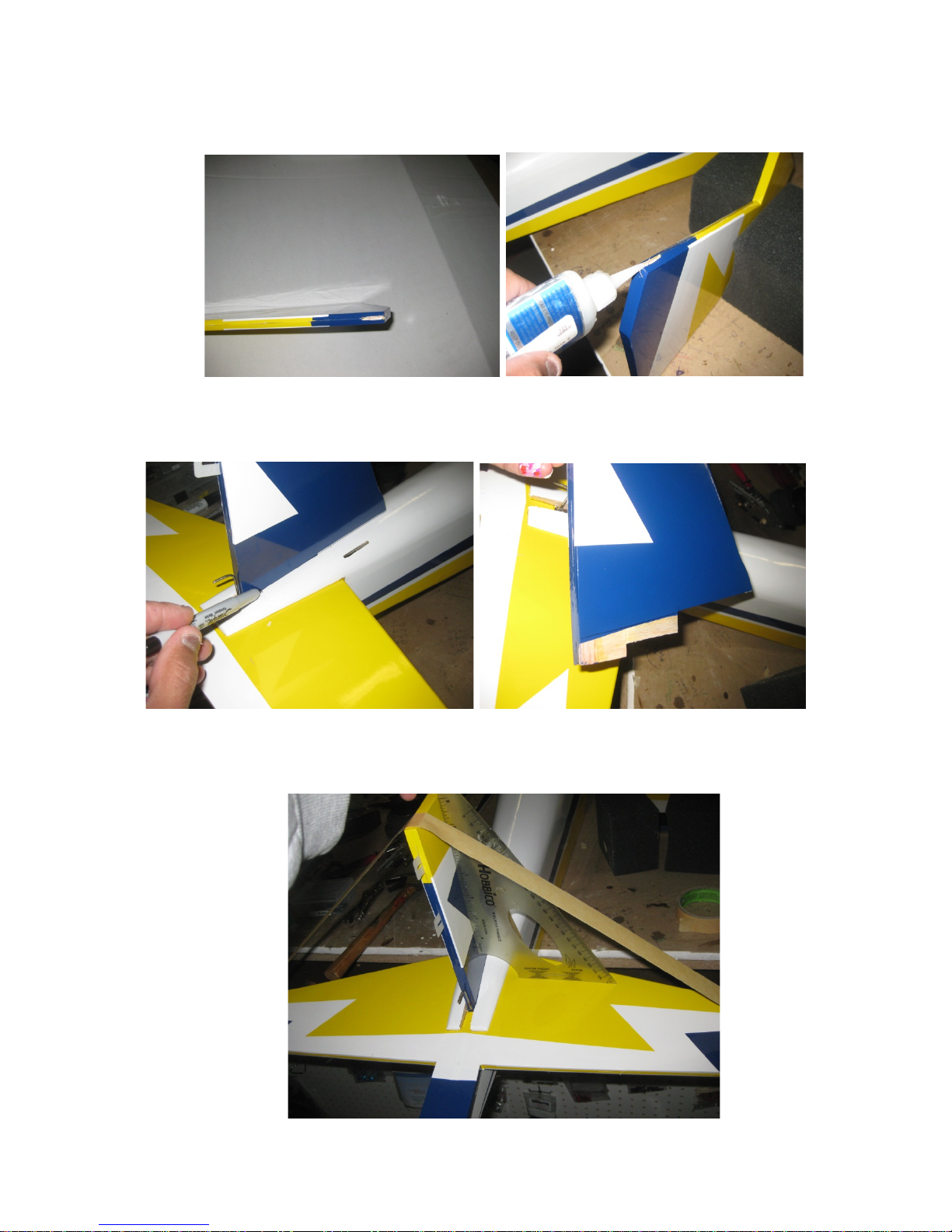
13. Prepare the rudder by cutting a slot to recess the tail gear wire. Also drill a hole the
size of the tail gear wire. Harden the cut and drilled area with thin CA.
14. Prepare the vertical stabilizer for gluing onto the fuselage. Cut off the covering as
shown below.
15. Mix some 30 minute epoxy and glue the vertical stabilizer onto the fuselag e. Use a
right angle triangle to make sure that the vertical stab is perpendicular to the horizontal
stabs.
Page 10
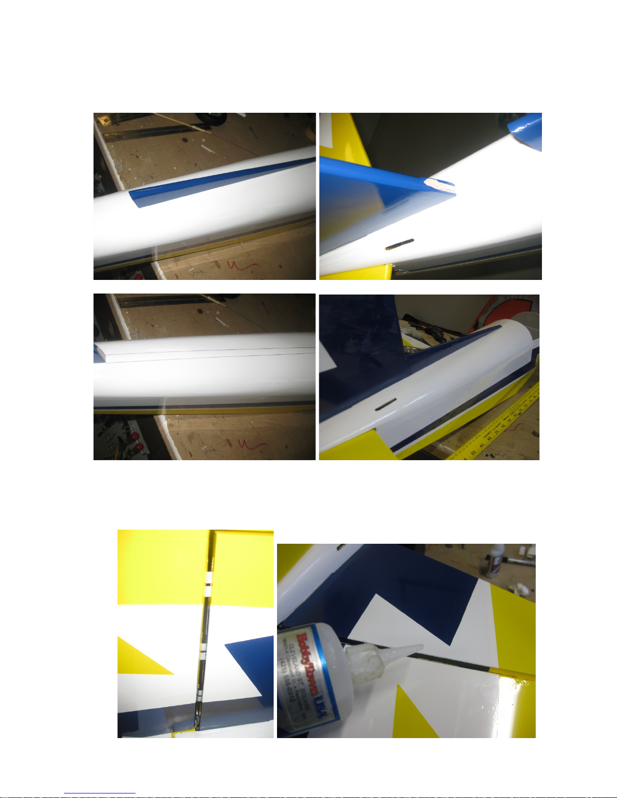
16. Locate the vertical stabilizer extension and prepare the fuselage for installation.
Remove the covering as shown in the pictures below. Glue it on with either medium CA
or epoxy.
17. Locate the rudder and hinges and prepare it for installation. Use a little epoxy in the
hole where the tail wheel tiller will reside to strengthen it. Install the rudder as shown
below and use thin CA to glue the hinges in place.
Page 11
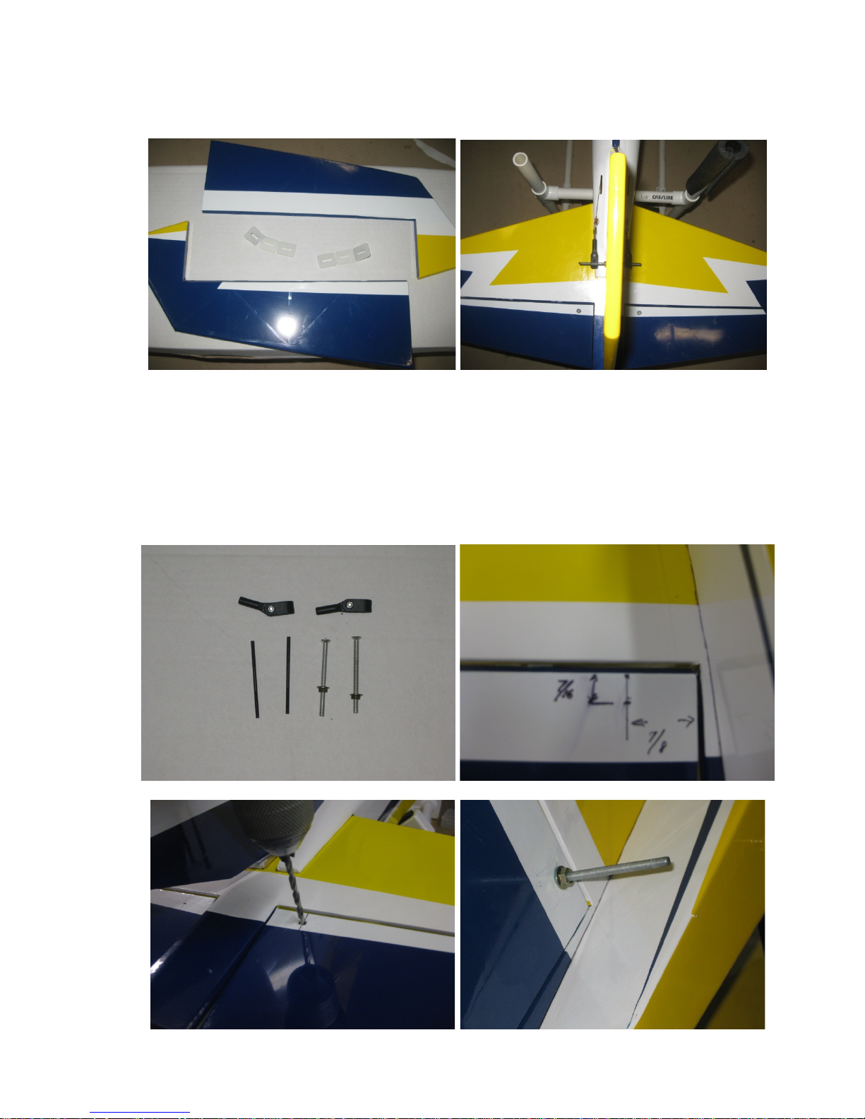
18. Locate the elevators and the hinges to glue in the elevators onto the horizontal
stabilizers. Glue it in using the same method as was used in the rudder installation
above.
19. Locate the control horns for the elevators and prepare for installation. See pictures
below for the locations for the control horn. You will need two servos on either side of
the fuselage.
Tip: Measure both sides of the elevators and drill a small pilot hole. Once it is squared
use a right drill bit and drill trough. You can use a countersunk bit on the top of the
elevators to provide a cleaner look. Once the hole is made, wick it with thin CA to
harden it.
Page 12
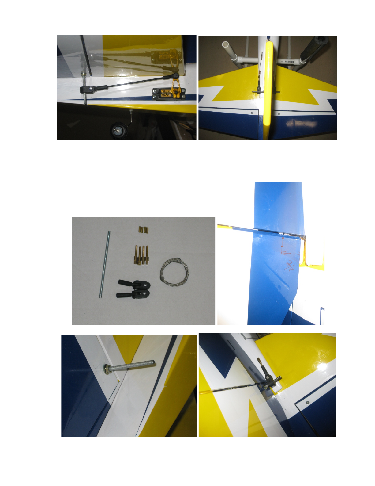
20. Locate the rudder control horn assembly. See pictures below for installation of the
control horns. Ensure that the rudder cables running through the slots do not rub the
fuselage.
Page 13
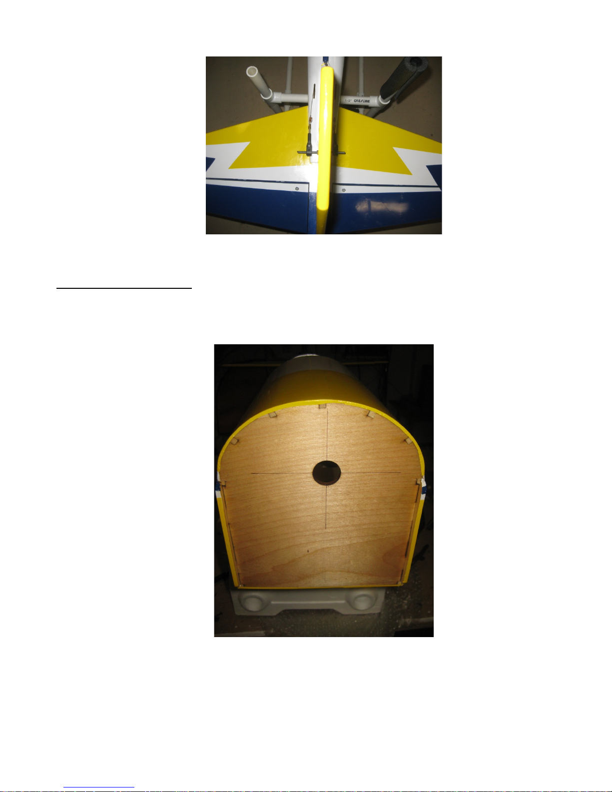
ENGINE INSTALLATION
1. Look at the firewall and you will see the lightly scribed centerline marked for the center
of your engine mount. You can darken it with a pen for visibility.
2. Mark the location of mounting bolts (Here, a DLE 30 is used). Drill out the mounting
holes for your mounting hardware.
Page 14
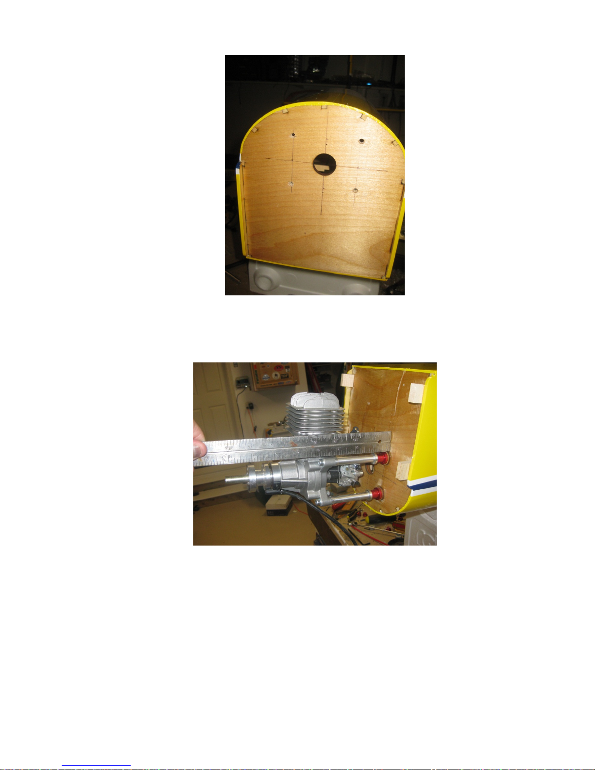
3. The distance of the firewall to the back plate of the spinner is about 7-31/4”. The
standoff length required will be 3-1/8”, which will give about a 1/8” clearance between
the back plate and the cowl. See pictures below for mounting the engine.
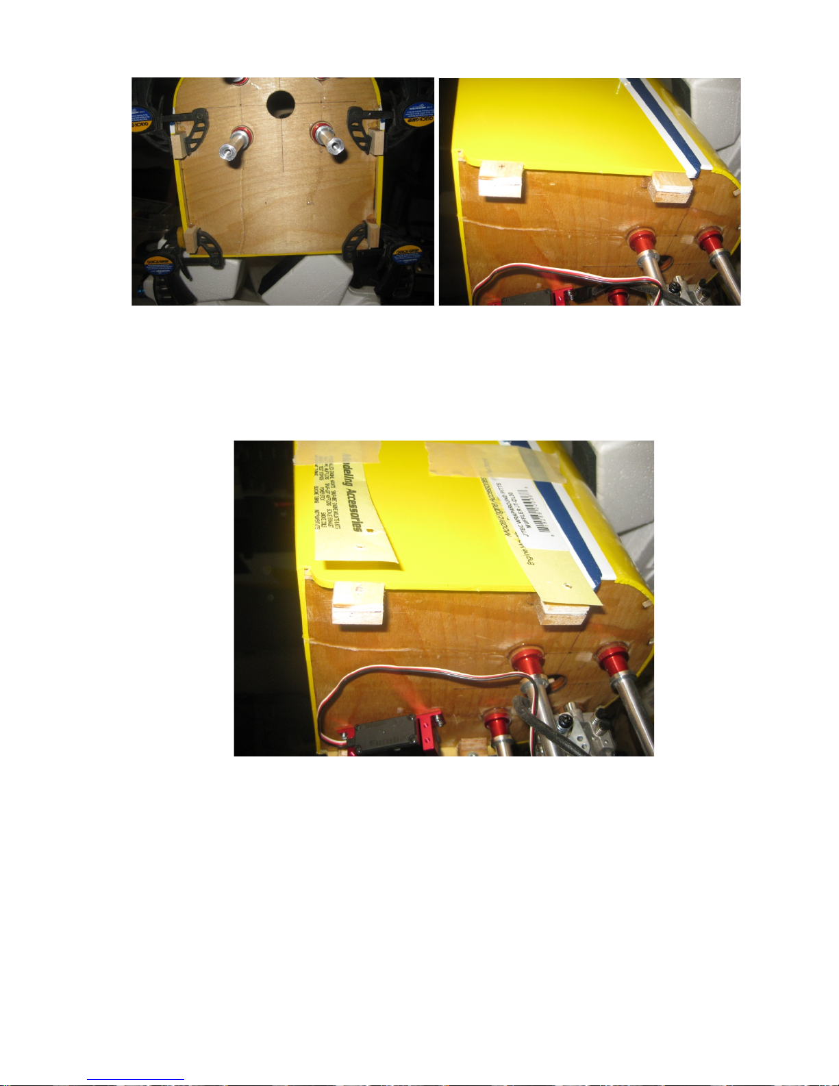
4. Locate the 4 mounting blocks for the cowl and install them as shown in the picture
below. Use 30 minute epoxy for the step. Place some scrap shims as shown in the
second pic below. The scrap shims will prevent cowl from being squeezed in and
damaging it.
Page 15
.
5. Now prepare to mark the cowl for installation. You will want to mount the engine and
use a 3” spinner back plate for use as a guide. Make some paper strip and tape them
to the fuselage as shown below. Drill a hole that will be big enough to accept a 4-40
screw (or you can use the wood screw provided which the author does not
recommend). You can install a blind nut on the other side of the mounting block.
6. Line up the cowl and drill out the holes for the 4 mounting bolts. It should look like the
picture below.
Page 16
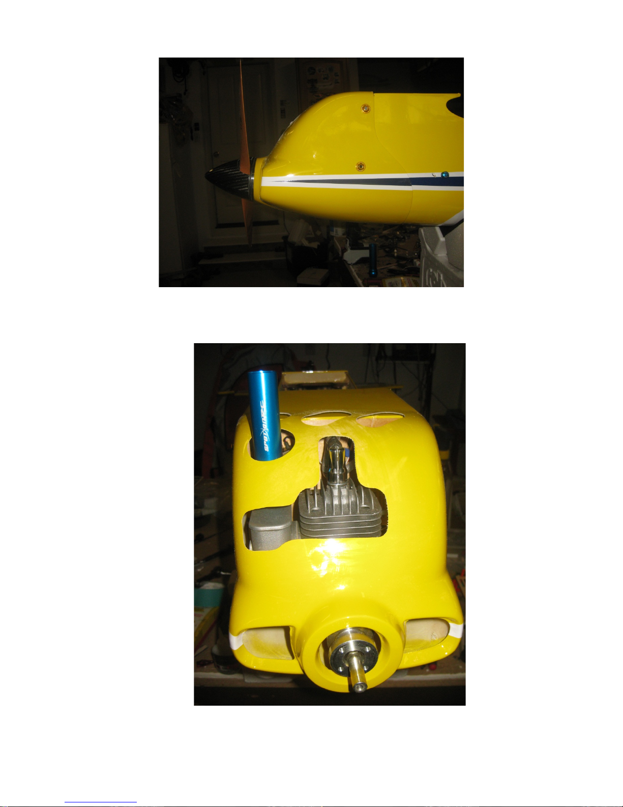
7. Cut out appropriate openings in the cowl for engine and muffler. Also make cuts in the
bottom of the cowl for cooling purpos es.
Page 17
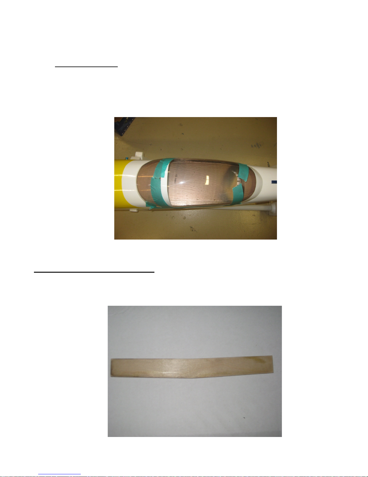
CANOPY INS TALL
1. Locate the canopy and align it on the fuselage as shown below. You will need
canopy glue for this step. Once you are satisfied with the alignment, apply the
canopy glue. Tape down the canopy with making tape so that it won’t move while it
is curing. Wipe off the excess glue with a damp paper towel.
WINGS AND MAINLANDING GEAR:
1. Locate the wing joiner and trial fit the joiner onto the wings to ensure a smooth fit. Also
mark the joiner as it has a dihedral on it.
Page 18
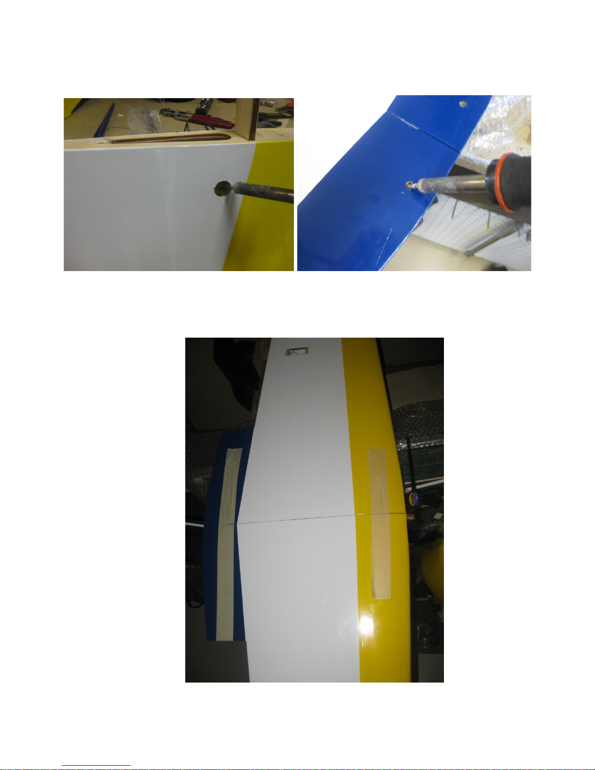
2. Use a hot soldering iron and carefully remove the covering where the servo wire will
come out of. Also use the soldering iron to remove the covering for the wing bolts.
3. Mix some 30 minute epoxy and apply it on the wing joiner and exposed ribs and glue
the two wing halves together. Use masking tape and clamps to hold the wing halves in
place while the epoxy cures.
Page 19
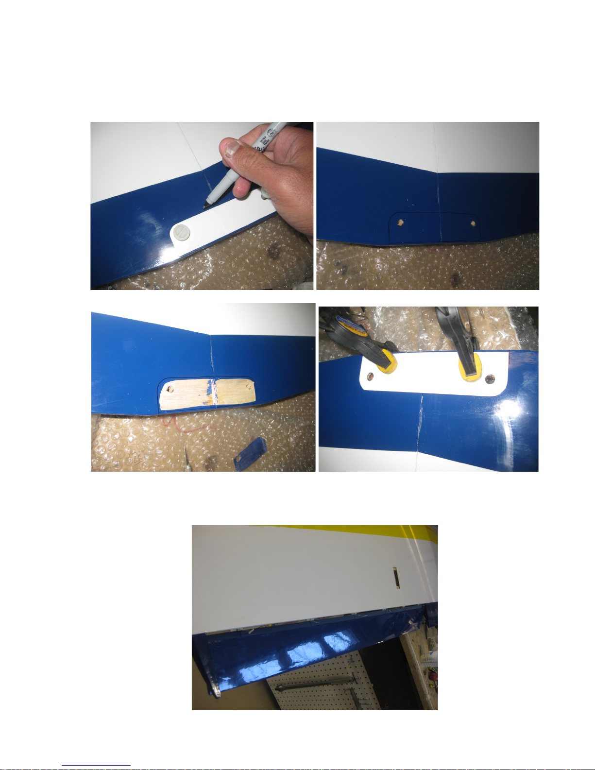
4. Locate the wing bolt reinforcement plate. Remove the covering where the wing bolts
will come through. Use the wing bolts and align it onto the bottom of the wings and
mark the area where the covering needs to be removed. Mix some epoxy and glue
down the wing bolt plate. See pictur es bel ow.
5. Locate the ailerons and prepare for installation onto the wings. Use thin CA and to glue
the aileron hinges in place.
Page 20
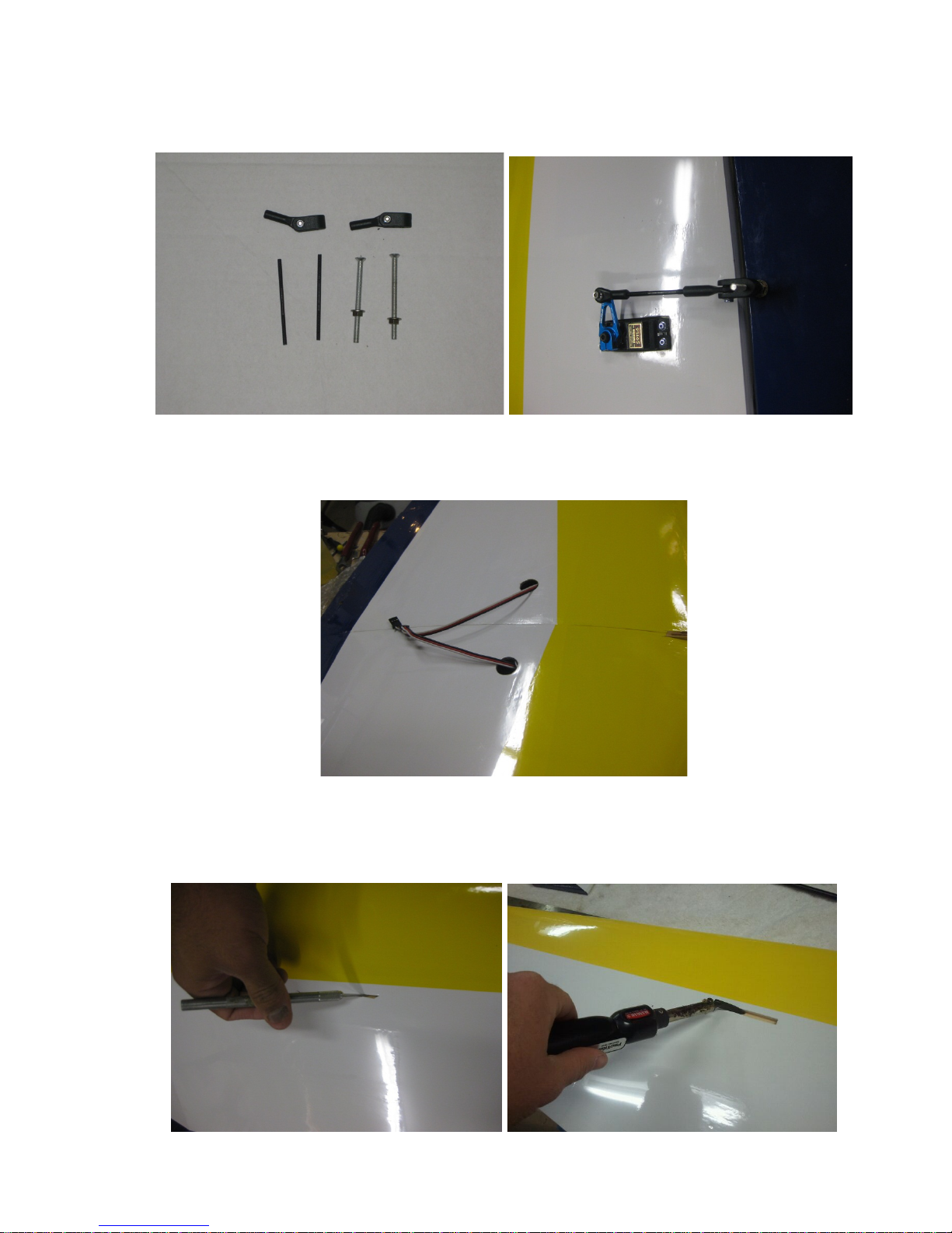
6. Locate the control horns and install them as shown in the pictures below. You can use
the same method as was used in the installation of the horns for the elevator.
7. Route the extensions lead out as shown below. There is a guide thread pre-installed in
the wings to help thread the servo wires.
8. Locate the slots on the bottom of the wings for the landing gear. Use a sharp Xacto
knife and cut the slot open carefully. Use a trim iron and iron down the covering as
shown in the pictures below.
Page 21
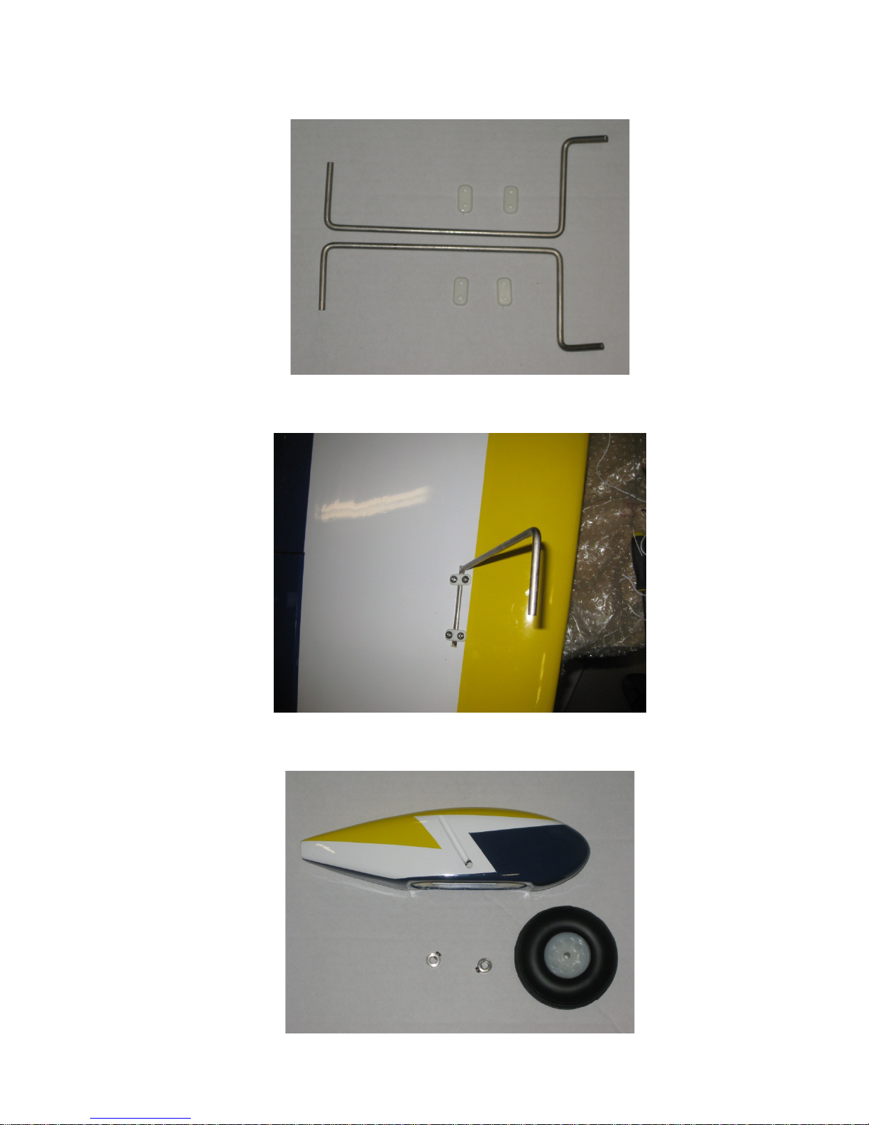
9. Locate the landing gear and securing hardware as shown below.
10. Install the gear as shown below. Harden the screw holes with CA.
11. Locate the wheel-pants, wheels, and the wheel collars.
Page 22
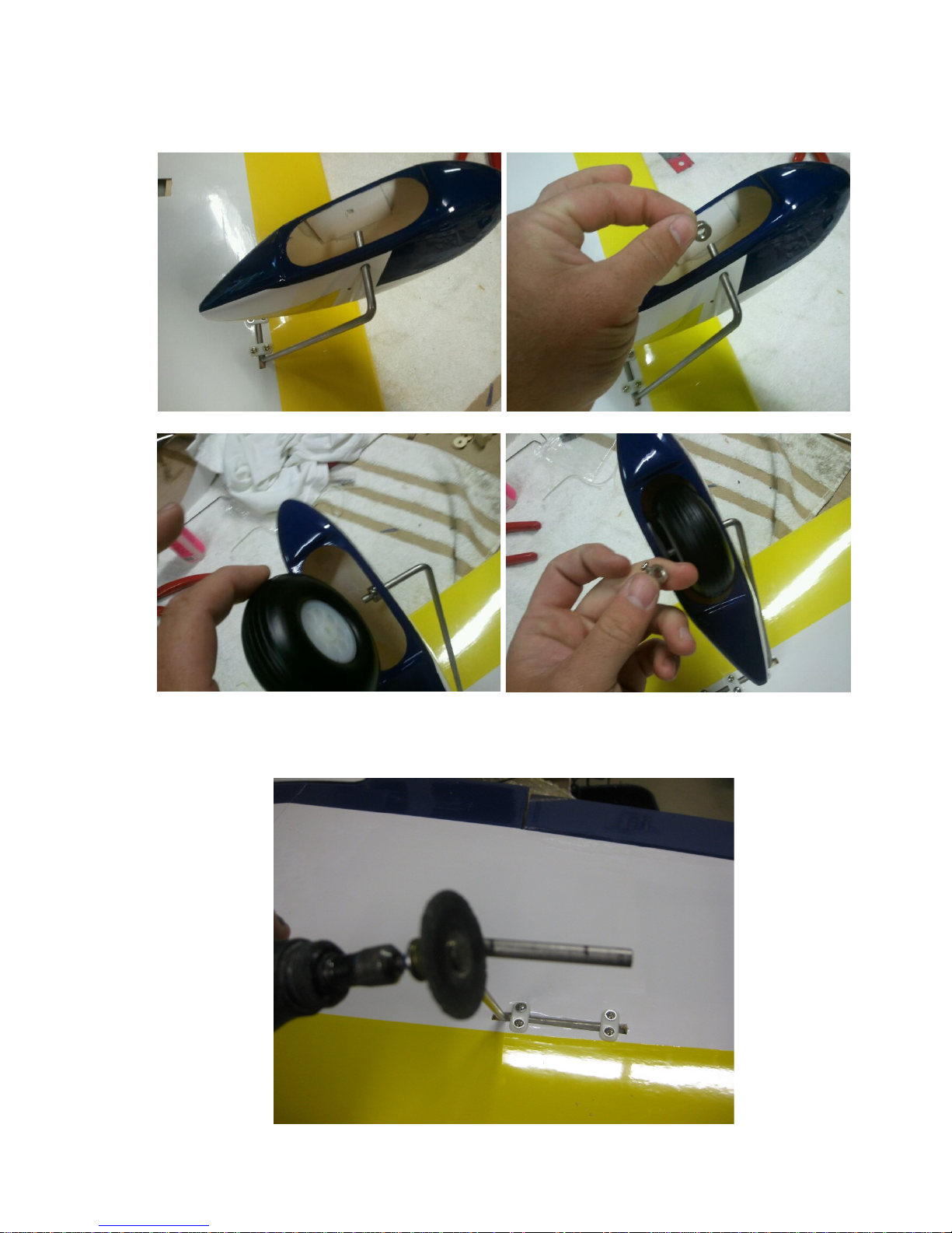
12. Install the wheel pants, wheel collars and wheels in the order shown in the pictures
below.
13. Prior to securing everything down, make a flat spot on the gear where the collars
reside so that they won’t slip.
Page 23
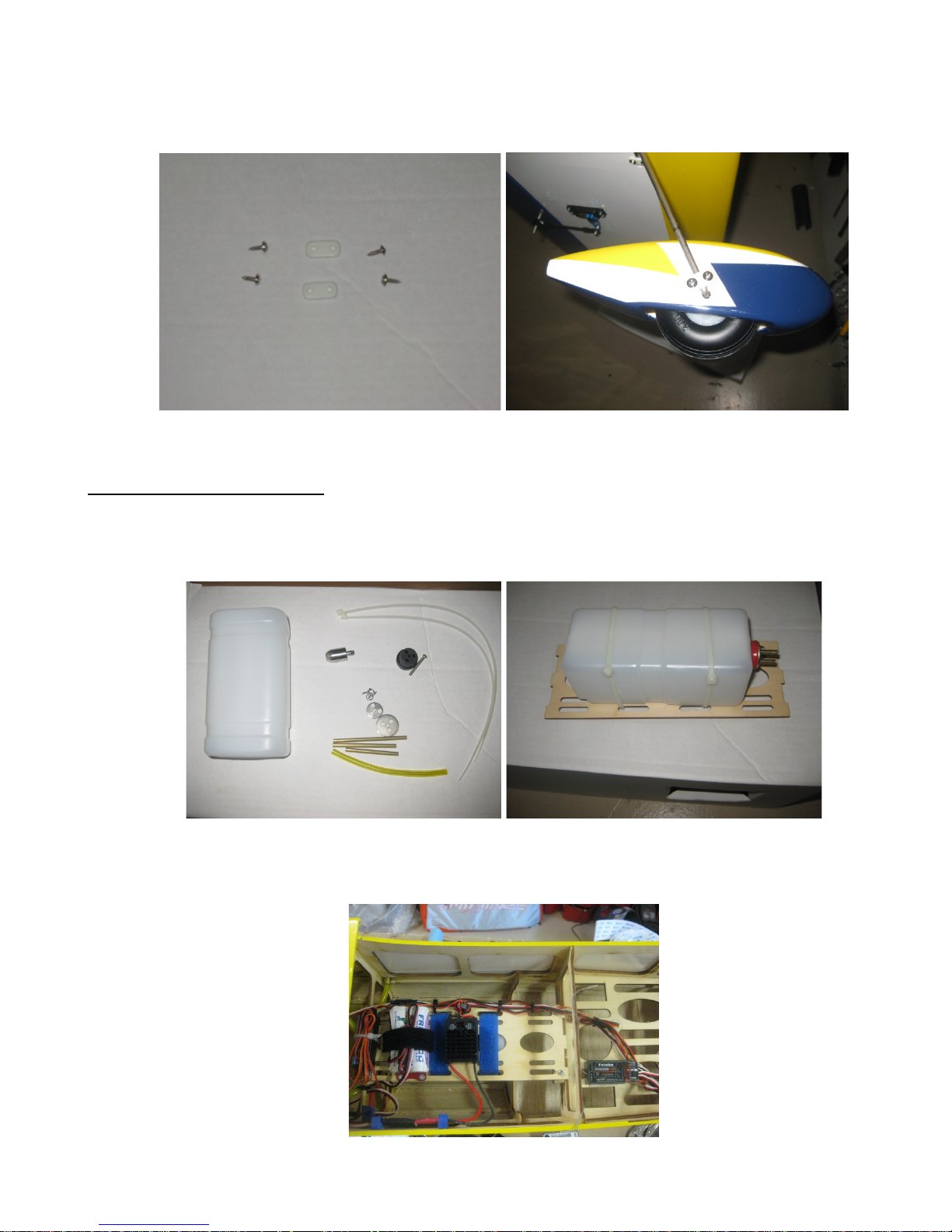
14. Reinstall the wheel pants, wheel and collars and secure everything. Locate the
mounting hardware to secure the wheel pants and install it as shown below.
FUEL TANK INSTALLTION:
1. Locate the tank mounting tray and the fuel tank. Mount the tank onto the tank tray as
shown below.
2. You can either glue in the tank tray permanently or make a ledge and screw it on
making it removable for servicing. See picture below.
Page 24

The above picture also shows the equipment install. This could vary based on
individual setup.
BALANCING AND PRE-FLIGHT:
The Chipmunk will balance right on the main wing spar. It is a very easy flying airplane
and fly and land very much like a trainer.
FINAL ASSEMBLY AND PRE-FLIGHT INSPECTI0NS:
1. Before arriving at your flying field, be sure all your batteries are properly
charged and all radio system are in proper working order.
2. Fill your fuel tank making sure your vent line is not plugged or capped. This is a
good time to check for any fuel leaks.
3. Check all control surfaces for secure hinges by performing a slight tug on the
control surfaces and observing if there is any give in the hinges. Check all
control rods, ball links, servo screws, etc. for proper operation and installation.
4. Check your batteries and perform a proper range check once again with the
engine off and running. Be sure all surfaces are moving in the correct direction
and the proper amount for your flying setup.
5. You are now ready for your maiden flight! Good luck and enjoy your new aircraft!
If you have any comments or questions about this manual or the aircraft please
email: [email protected]
 Loading...