

Page 1
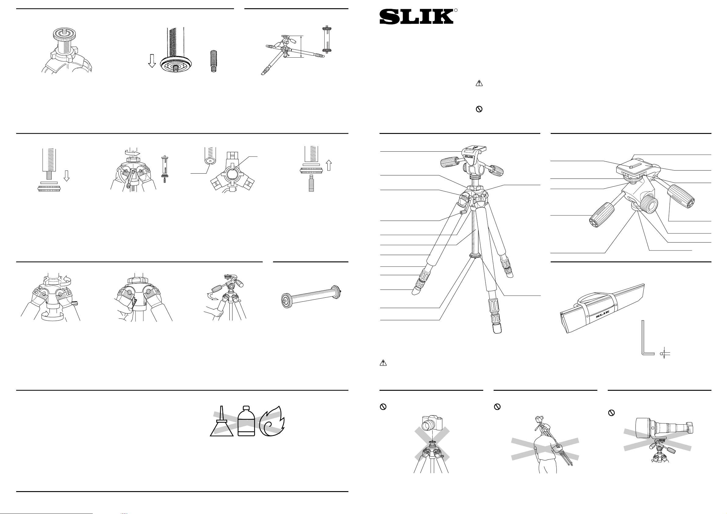
Using the short center column
1. Remove the lower base plate
and the rubber ring.
2. Loosen the center column tension adjustment knob and nut
three or four complete turns.
Adjustment of the center column
play can be accomplished by
locking a screw with the enclosed
allen wrench.
1. Unlock center column tension
adjustment knob and nut.
3. Turn the elevation control handle to check the tightness of
the center column. Also check
for any play by moving the
head while keeping the legs
steady.
4. If the center column is too tight,
use the allen wrench to loosen
the screw and adjust.
5. Match the groove of the short
center column to the Key guide
inside the body of the tripod.
Check to be sure this is perfectly matched.
6. Turn the elevation control handle
to engage the gear on the short
center column. Check to be
sure operation is smooth.
2. Insert enclosed allen wrench
into wrench hole and tighten
the screw.
Adjustment of center column play (after using tripod)
3. Using the elevation control
handle, crank out the center
column, while holding on to the
head.
4. Remove the rubber ring and
lower base plate from the short
center column.
If not, recheck positioning as
described in (5).
7. Replace the rubber ring and
base plate.
8. Be sure to attach the rubber
ring and base plate to the center column that you just
removed to prevent loss.
Options
SHORT CENTER COLUMN FOR
PROFESSIONAL
Ⅱ
Reversible threaded post
1. The threaded post on the upper end of the
center column is 3/8". The threaded post on
the lower end of the center column is
reversible, 1/4" and 3/8". If 1/4" post is needed at the top, reverse the center column
itself (see “Using the short center column”)
2. To reverse a post, first loosen the base
plate.
Then remove the post, reverse it, and reinsert it. Retighten the base plate.
Note: When reversing the lower threaded
post, move the rubber ring up first.
Short Center Column
For the lowest possible camera angle with the
legs fully spread, a special short center column
is available as an optional accessory.*
This makes the lowest position 370 mm (14 7/12")
from the ground.
PROFESSIONAL Ⅱ-LE
Operating Instructions
Congratulation on the purchase of a SLIK Professional Ⅱ-LE.
SLIK Corporation has designed your tripod to be a sturdy, rugged,
dependable product that will provide you with many years of satisfactory use.
Please take a few moments to read this operating instruction carefully before use so that you can take full advantage of your Tripod's
many fine features.
Retain this operating instruction in case you might want to refer back to it.
Caution
This caution icon refers to information pertaining to important safety
procedures in preventing injuries, or damages which may occur as a
result of mishandling this product.
Prohibition
This prohibited icon refers to information pertaining to prohibited contents. Please refer to instructions closely to avoid accidents.
Components
G079-1
This product has been designed to handle
equipment weighing under 10 kgs (22 lbs).
Do not overload.
Some equipments weighing under 10 kgs (22
lbs), such as long lenses, may not balance well
due to its weight distribution. In such case,
please use a larger tripod.
Carrying a tripod with a camera left on can
result in unexpected accidents. We therefore,
recommend you to remove your camera while
carrying the tripod.
Equipment that can be loaded on
this tripod
Prohibition
Prohibition
Carrying the tripod
Specification
Folded length 810mm
(31 11/12")
Max. operating height 1,835mm
(72 1/4")
Max. center column ext. 285mm
(11 1/4")
Weight 4.9kg
(10lbs 13oz)
Do not attach a camera directly to the pan
head attachment screw of the center column.
This may damage both your camera and tripod.
Prohibition
Pan head attachment screw
Accessory
Pan head
Caution
Soft Grip is consumption and cannot be used permanently.
Please replace it whenever ragged.
Printed in Thailand.
Care of the Tripod
OIL
THINNER
・DO NOT apply any grease or oil to this product.
・Clean with a mild detergent and a soft cloth only.
・DO NOT use close to flame. Avoid extreme heat.
Slik corporation reserves the right to make changes in design and/or improvements on the products without any obligation and advanced notice.
SLIK CORPORATION
853 Kayama, Hidaka City, Saitama 350-1231, Japan Phone 81-42-989-2141, Fax. 81-42-985-0210 ©2006
370 mm
(14 7/12)"
R
Key
Groove
Pan head
Center column tension
adjustment nut
3-Position leg angle
adjustment lock
Elevation control handle
Lower center column
tension adjustment nut
Center column
Soft grip
Leg
Leg lock nut
Rubber leg
tips
Rubber ring
Reversible threaded post
Main body
Base plate
1/4" Camera
mounting screw
Camera locking knob
Camera mounting screw
Pan & tilt handle
3/8" Tripod attachment
female screw
Tripod case
3/8" Camera mounting screw
Camera platform
Dual axis
bubble levels
Vertical tilt handle
Panning lock knob
Panning Guide
Pan/Tilt head stand
Allen wrench
(2mm width)
Page 2

Bubble Levels
Two bubble levels are built-in for vertical and
horizontal positioning.
Changing the camera mounting screw
1. Both 1/4" and 3/8" camera mounting screws
are supplied.
The screw not in use is stored in the side of
the camera platform.
2. Remove the camera mounting screw through
the large end of the mounting track.
It’s a good idea to tighten the camera locking
knob when a camera is not attached to prevent loss of the mounting screws.
Attaching a Camera
1. Hold the camera firmly, and turn the camera
mounting screw to engage the threads.
2. Lock the camera tightly with the knurled
camera locking knob.
3. Tilting the head forward makes it easier to
attach the camera.
Attaching the head to the center column
Loosen the panning lock knob and rotate the base of the head clockwise
to screw it tightly onto the center column.
Tighten the panning lock knob and turn the head clockwise, using both
handles, to tighten as much as possible.
Unlock the panning lock knob for easy panning.
Lock the panning lock knob tightly, then grasp the pan handle and turn
the head counter-clockwise to loosen.
Then loosen the panning lock knob and it will be easy to unscrew the
head by rotating the base of the head counterclockwise.
Removing the head from the center column
The pan handles are installed as shown with
the long handle on the left, for pan and tilt
movement; the short on the right, for vertical
tilt. If you prefer to have it the other way
around, the tripod will function perfectly.
Install the pan handles
The vertical & tilt handle can be reset inside the
pan & tilt handle by screwing from rear of the
handle as shown here.
The head is installed by screwing it onto the
center column’s 3/8" threaded post socket
hole.
Attach the head
Positioning the elevation
control handle
Raise the elevation control handle into position
by pulling out on the knob to lock it into place.
Operating the center column
1. The center column can be moved up and
down by turning the elevation control handle.
The center column tension adjustment knob
adjusts the tightness of the column and
helps prevent vibration.
2. The worm gear column adjustment mechanism will not move even if pressure is placed
on the head with the tension adjustment
knob unlocked. Note-the column can be
moved, with the elevation control handle,
even when the tension adjustment knob is
fully locked.
The lower center column tension adjustment
nut is used when necessary to adjust the tightness of the center column.
Lower Center Column Tension
Adjustment Nut
Extending legs
1. Release the leg locks by rotating one half
turn.
Because leg are grooved, the leg locks can
be released in any order.
2. The second section, form the top, in each
leg has reference marks every 10 cm for precise height adjustment.
Three-position adjustable legs
1. When opening each leg, it will stop at the
first (standard) position. To change the angle
of each leg, move the leg a little closer to the
center column and pull the leg angle adjustment lock out one click. The leg will be
released and can be opened to the second
position. To move to the third position, again
pull the leg angle adjustment lock out one
click.
2. After choosing the desired leg angle, securely push in the adjustment lock.
When all legs are opened fully, the lowest
position is 585 mm (23 1/12") from the
ground.
An optional short center column* permits
shooting as low as 370 mm (14 7/12").
Panning guide
A rotating scale at the base of the head makes
it easy to set exact shooting angle.
To begin, set the mark at the base of the head
on “0”.
Using the pan head
1. Loosen the panning handle, and the head
will move freely front to rear.
2. Loosen the panning lock knob, and the head
will rotate.
3. Loosen the vertical tilt handle and the level
can be adjusted.
The pan head is specially lubricated for
smooth movement.
585 mm
(23 1/12")
Lower center column
tension adjustment nut
 Loading...