

Slightly Nasty 2251 Construction & Operation Manual
M O D E L 2251
M U LT IB AN D FI LT E R
L OW
N O T C H
H I G HB A N D
G A I NVC A I N VC A O U T
1
1 5 0
1 0
1 . 8 k
2 0 k
4
4 0
5 2 0
6 . 5 k
+
+
-
+
-
M O D E L 2 2 5 1
M u l t i b a n d F i l t e r
Co nstr ucti on
& Op erati on G uid e
R E V A - F OR P CB V 1 .0
S L I G H T L Y N A S T Y E L E C T R O N I C S A D E L A I D E , A U S T R A L I A
S L I G H T LY N A S T Y E L E C T R O N I C S A D E L A I D E , A U S T R A L I A
2
Specificat i o ns
S P E C I F I C A T I O N S
PHYSICAL
FORM FACTOR: Loudest Warning / 4U
WIDTH: 3NMW / 75.5mm
HEIGHT: 175mm
DEPTH: ~40mm from panel front inc. components
PCB: 70 x 75mm, Two-Layer Double Sided
CONNECTORS: 4mm Banana
ELECTRICAL
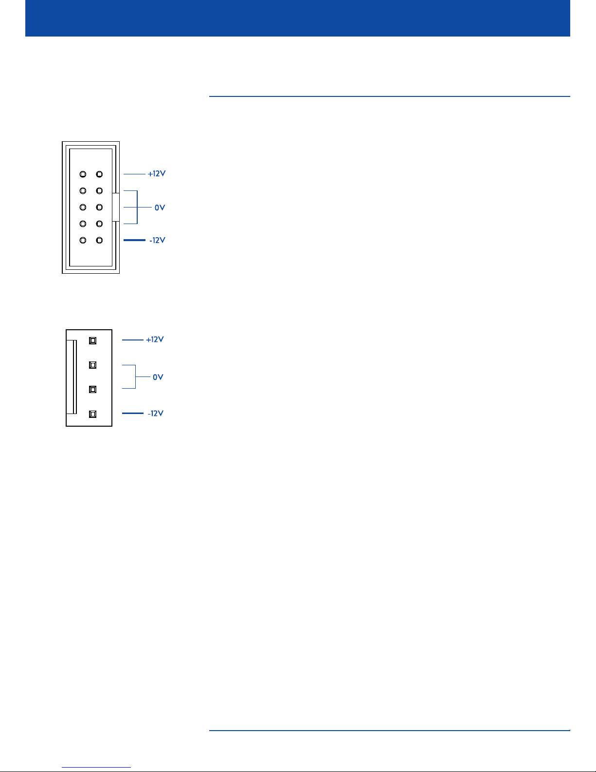
POWER: +12V, 0V, -12V
CONSUMPTION: ~25mA +12V Rail, ~25mA -12V Rail
CONNECTOR: IDC 10-pin Shrouded Header, Eurorack Standard
or MTA-156 4-Pin Header
I/O IMPEDANCES: 100K input, 1K output (nominal)
INPUT RANGES (nominal)
SIGNALS: +/- 5V
FREQ: +/- 5V
RES: +/- 5V
GAIN: 0 - 5V
OUTPUT RANGES (nominal)
OUTPUT (ALL): +/- 5V
M O D E L 2 2 5 1
M u l t i b a n d F i l t e r
IDC power connector pinout.
MTA-156 power connector pinout.

S L I G H T L Y N A S T Y E L E C T R O N I C S A D E L A I D E , A U S T R A L I A
3
Circ u i t Ove r view
T A B L E O F C O N T E N T S
SPECIFICATIONS
Specifications / Power Requirements 2
INTRODUCTION
Introduction 4
CIRCUIT OVERVIEW
Circuit Overview 5
Signal / Res CV Inputs 6
Exponential Converters 6
Filter Core 8
Extra VCA 10
CHOOSING COMPONENTS
Bill Of Materials (BOM) 11
Choosing Components 12
CONSTRUCTION
Construction Overview 13
Physical Assembly 14
CALIBRATION
Calibrating the 2251 15
CONTROLS
Controls 17
REFERENCE
PCB Guide 18
M O D E L 2 2 5 1
M u l t i b a n d F i l t e r
This document is best viewed
in dual-page mode.
S L I G H T L Y N A S T Y E L E C T R O N I C S A D E L A I D E , A U S T R A L I A
4
Intro d u c t i o n
I N T R O D U C T I O N
The Slightly Nasty Model 2251 Multiband Filter is a versatile multimode 12dB/
Oct state-variable filter that provides four simultaneous filter outputs: lowpass,
highpass, bandpass, and notch. Both cutoff frequency and resonance are CVcontrollable, with attenuverters provided for both. A dedicated audio FM knob
allows add extra texture to be added without tying up an external mixer. In
addition, one of the unused LM13700 OTA stages is used to implement a bonus
utility VCA that operates independently of the filter.
The 2251 was designed to provide very controlled and consistent resonance
across the operating range, so that very dynamic CV control of the resonance
within a patch would always result in controlled and predictable signal
amplitudes without excessive distortion or clipping. The resulting character of
the filter is quite smooth, while still providing a satisfyingly big analogue filter
sound suitable for basses, leads, and general sound design.
Despite this self-limiting resonance, the filter still self-oscillates and can be
"pinged" by setting the resonance on the threshold of oscillation and hitting the
audio input with a transient signal.
The Audio FM knob allows for some additional dirt and texture to be easily
added by modulating the cutoff frequency with the input signal, which results in
a sound somewhere between soft distortion and harmonic FM. The extra VCA is
ideal as a final envelope/output VCA, meaning that a single oscillator and 2251
filter can provide a complete signal path for basic subtractive synth sounds.
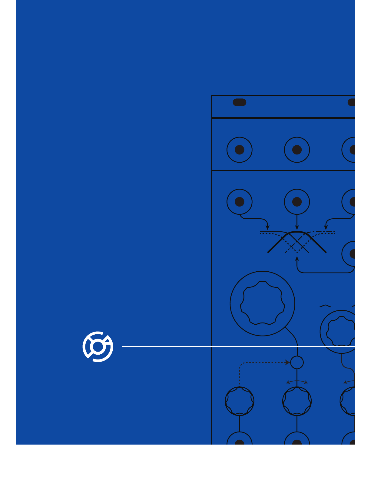
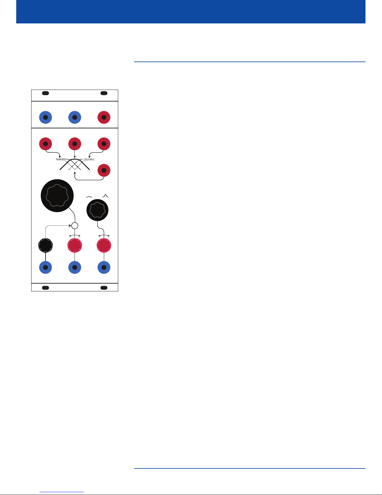
The Model 2251 uses the Loudest Warning 4U format for the front panel, and
follows Eurorack electrical and power standards. All front panel components are
PCB mounted for easy wiring-free construction. The front panel is available in
two finishes - satin anodised and gloss white powdercoat, both on 2.5mm
aluminium with robust UV-printed graphics.
MO DE L 22 51
MU LTI BA N D FI LTE R
SL IG HT LY NA ST Y
FR EQ .
IN PU T
RE S.
LO W
NO TC H
HI GHBA ND
GA INVC A IN VC A OU T
1
15 0
10
1. 8k
20 k
4
40
52 0
6. 5k
+
+
-
+
-
M O D E L 2 2 5 1
M u l t i b a n d F i l t e r
S L I G H T L Y N A S T Y E L E C T R O N I C S A D E L A I D E , A U S T R A L I A
5
Circ u i t Ove r view
C I R C U I T O V E R V I E W
For full schematics, please download the separate schematics PDF. Excerpts shown
in this manual may be outdated and are provided for reference only.
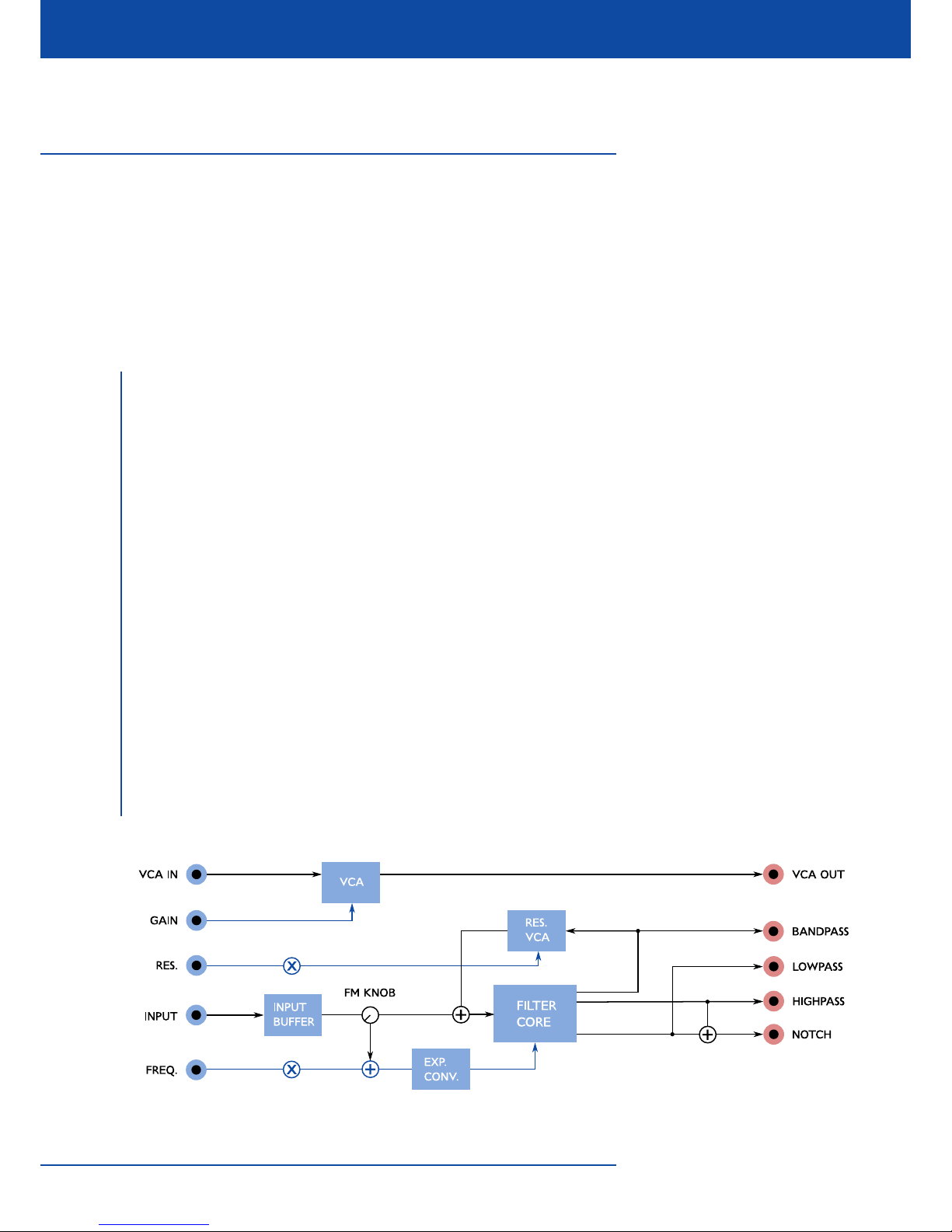
The 2251 is really a fairly basic module in terms of architecture, with a filter core
surrounded by some simple buffering and CV processing elements, along with a
bonus utility VCA. The functional blocks are divided as follows in the schematics:
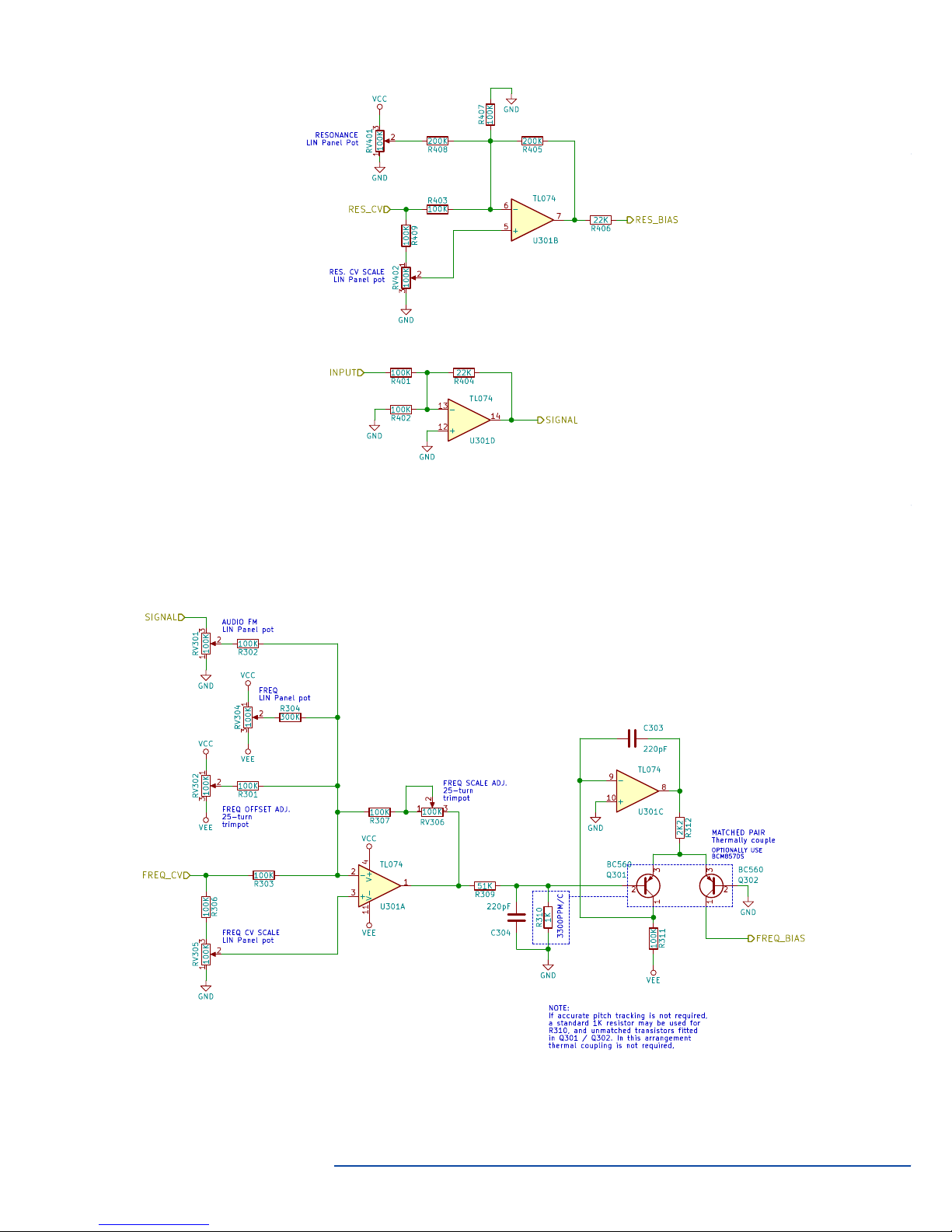
1. CV/Signal buffers - These buffer the inputs for the resonance CV and
the audio signal input. The resonance CV buffer also serves as an
attenuverter for additional control functionality.
2. Exponential Converter - This converts the linear input CV into an
exponential current that controls the cutoff frequency of the filter core.
This also includes the buffer/attenuverter for the frequency CV input
and associated front panel controls. This allows for the possibility 1V/
Oct tracking (with careful setting of the attenuverter!) and can also be
temperature compensated if desired.
3. Filter Core - The filter core is a 2-pole state-variable design that
provides simultaneous lowpass, highpass, and bandpass outputs, with a
VCA-modulated feedback path creating a voltage controlled, self-
limiting resonance. An additional mixer stage creates a notch output by
mixing the low- and high-pass signals.
4. Extra VCA - As half of one of the LM13700 OTA ICs is unused by the
rest of the circuit, a bonus VCA can be provided to extend the
functionality of the module.
Block diagram of the Model 2251.
Circles marked "X" are attenuverters.
M O D E L 2 2 5 1
M u l t i b a n d F i l t e r
+
5
-
6
7
U301B
TL074
R405
200K
RES_CV
1
2
3
RV402
100K
GND
RES. CV SCALE
LIN Panel pot
R403
100K
1
2
3
RV401
100K
RESONANCE
LIN Panel Pot
R406
22K
RES_BIAS
+
12
-
13
14
U301D
TL074
R402
100K
R404
22K
GND
R401
100K
GND
INPUT
SIGNAL
GND
R407
100K
VCC
R408
200K
GND
R409
100K
S L I G H T L Y N A S T Y E L E C T R O N I C S A D E L A I D E , A U S T R A L I A
6
Circ u i t Ove r view
1
2
3
Q301
BC560
1
2
3
Q302
BC560
R312
2K2
+
10
8
-
9
U301C
TL074
GND
R311
100K
VEE
VEE
VCC
GND
FREQ_BIAS
1
-
2
+
3
U301A
TL074
R307
100K
R309
51K
R310
1K
3300PPM/C
GND
123
RV306
100K
FREQ SCALE ADJ.
25-turn
trimpot
R301
100K
1
2
3
RV302
100K
VEE
VCC
FREQ OFFSET ADJ.
25-turn
trimpot
R306
100K
FREQ_CV
1
2
3
RV305
100K
GND
FREQ CV SCALE
LIN Panel pot
R304
300K
1
2
3
RV304
100K
VCC
VEE
FREQ
LIN Panel pot
MATCHED PAIR
Thermally couple
OPTIONALLY USE
BCM857DS
C303
220pF
C304
220pF
SIGNAL
1
2
3
RV301
100K
GND
AUDIO FM
LIN Panel pot
R302
100K
R303
100K
NOTE:
If accurate pitch tracking is not required,
a standard 1K resistor may be used for
R310, and unmatched transistors fitted
in Q301 / Q302. In this arrangement
thermal coupling is not required,
V-
11
V+
4
Resonance CV Input
Signal Input
Exponential Converter
 Loading...