

SLI M1689, S1689 User Manual

S1689
ULi M1689
Micro-ATX Motherboard
User’s Guide
1

Declaration of Conformity
According to 47 CFR, Parts 2 and 15 of the FCC Rules
The following designated product:
EQUIPMENT: MAINBOARD
is a Class B digital device that complies with 47 CFR Parts 2 and 15 of the FCC
Rules. Operation is subject to the following two conditions:
1. This device may not cause harmful interference.
2. This device must accept any interference received, including interference that
may cause undesired operation.
This declaration is given to the manufacturer:
CHAINTECH AMERICA CORP.
4427 Enterprise St. Fremont, CA 94538, U.S.A.
http://www.chaintechusa.com
Chaintech President: Simon Ho
Signature:
2

Federal Communications Commission Statement
100%
This device complies with FCC Rules Part 15. Operation is subject to the following two conditions:
* This device may not cause harmful interference.
* This device must accept any interference received, including interference that may cause undesired operation.
This equipment has been tested and found to comply with the limits for a Class B digital device, pursuant to
Part 15 of the FCC Rules. These limits are designed to provide reasonable protection against harmful interference
in a residential installation. This equipment generates, uses, and can radiate radio frequency energy. If this
equipment is not installed and used in accordance with the manufacturer's instructions, it may cause harmful
interference to radio communications. However, there is no guarantee that interference will not occur in a
particular installation. If this equipment does cause harmful interference to radio or television reception, which can
be determined by turning the equipment off and on, the user is encouraged to try to correct the interference by one
or more of the following measures:
* Reorient or relocate the receiving antenna.
* Increase the separation between the equipment and receiver.
* Connect the equipment to an outlet on a circuit different from that to which the receiver is connected.
* Consult the dealer or an experienced radio/TV technician for help.
The use of shielded cables for connection of the monitor to the graphics card is required to assure
compliance with FCC regulations. Changes or modifications to this unit not expressly approved by the party
responsible for compliance could void the user's authority to operate this equipment.
Canadian Department of Communications Statement
This digital apparatus does not exceed the Class B limits for audio noise emissions from digital apparatuses
set out in the Radio Interference Regulations of the Canadian Department of Communications.
Manufacturer's Disclaimer Statement
The information in this document is subject to change without notice and does not represent a commitment
on the part of the vendor. No warranty or representation, either expressed or implied, is made with respect to the
quality, accuracy or fitness for any particular purpose of this document. The manufacturer reserves the right to
make changes to the content of this document and/or the products associated with it at any time without obligation
to notify any person or organization of such changes. In no event will the manufacturer be liable for direct, indirect,
special, incidental or consequential damages arising out of the use or inability to use this product or documentation,
even if advised of the possibility of such damages. This document contains materials protected by copyright. All
rights are reserved. No part of this manual may be reproduced or transmitted in any form, by any means or for any
purpose without expressed written consent of its authors. Product names appearing in this document are mentioned
for identification purposes only. All trademarks, product names or brand names appearing in this document are
registered property of their respective owners.
Printed in Taiwan.
JAN 2004
OST-CONSUMER
RECYCLED PAPER
3

TABLE OF CONTENTS
Chapter 1 Introduction............................................................1
1-1 Product Specifications..................................................................................1
1-2 Package Contents.........................................................................................2
1-3 Back Panel...................................................................................................3
1-4 Motherboard Layout.....................................................................................3
Chapter 2 Hardware Setup.....................................................4
2-1 PC D.I.Y. Assembly Instructions...................................................................4
2-2 自行組裝電腦之作業指導重點 (Chinese)..................................................6
2-3 Français Instructions de montage du PC D.I.Y (French)................................8
2-4 Deutsch PC D.I.Y.-Montageanleitung (German).........................................10
2-5 Самостоятельная сборка ПК (Russian)....................................................12
2-6 PC D. I. Y. 조립 설명 (Korean)...............................................................14
2-7 Connector and Jumper Settings...................................................................16
Chapter 3 BIOS Setup Program...........................................20
3-1 Standard CMOS Setup................................................................................20
3-2 Advanced BIOS Features............................................................................20
3-3 Advanced Chipset Features.........................................................................21
3-4 Integrated Peripherals.................................................................................21
3-5 Power Management Setup..........................................................................21
3-6 PNP/PCI Configurations.............................................................................21
3-7 PC Health Status.........................................................................................21
3-8 Frequency/Voltage Control.........................................................................21
3-9 Load Optimized Defaults............................................................................21
3-10 Set Password............................................................................................21
3-11 Save and Exit Setup..................................................................................22
3-12 Exit Without Saving.................................................................................22
Chapter 4 Software................................................................23
4-1 Driver Setup...............................................................................................23
Appendix.................................................................................28
How to Install Windows 2000/XP On a SATA Drive.........................................28
4

Revision History
Revision Description P/N
V.1_M Original Issue 9413507010
5

Chapter 1 Introduction
1-1 Product Specifications
CPU
- Supports AMD Socket-939 Althon 64 / Sempron CPU
- Processor interface via 2000MT/s HyperTransport bus
Chipset
- ULi M1689
Memory
- Four 184- pin DDR DIMMs up to 4GB
- Supports Dual Channel DDR266/333/400 memory
Due to CPU specifications limitation, two DDR400 memory
Chapter 1
modules inserted into DIMM1/3, three DDR400 into DIMM1/2/3,
or four DDR400 into DIMM1/2/3/4 is not recommended.
Expansion Slots
- One AGP slot for 8X/4X AGP
- Five 32-Bit PCI slots (v2.2 compliant)
5.1 Channel Audio
- With external high quality 5.1-channel AC’97 Codec
- Complete software driver supports for Windows OS
SATA
- Supports four native SATA 1.5Gb/s devices
- Hot-swap capability, allowing disks to be changed without powering down the
system.
- Supports SATA ATAPI devices
IDE
- Supports 2 UltraDMA-66/100/133 IDE Ports
FDD
- One FDD connector supports up to 2.88 MB
USB 2.0
- Built-in VT8237R supports total 8 USB 2.0/1.1 ports
- Supports USB 2.0 High-Speed Device @480 Mb/s Transfer Rates
1

Chapter 1
Fast Ethernet
- Supports 10/100Mb Fast Ethernet with external Realtek PHY
Boot-Block Flash ROM
- Award system BIOS supports PnP, APM, DMI, ACPI, & Multi-device
Booting features
Rear Panel I/O ports
- PS/2 Mouse and Keyboard port
- Four USB ports and one RJ45 connector
- Two 9-pin D-Sub male Serial ports
- 25-pin D-Sub female Parallel port
- Audio I/O jacks (Line-in, Line-out and Mic-in)
Internal I/O connectors
- Two 3x1 pin fan connectors
- Two 5x2 pin USB connectors for additional 4 USB ports
- 3x1 pin wake on LAN connector with housing
- Two 4x1 pin CD-in connectors
- 5x2 pin Front Audio connector
- 10x2 pin Front Panel connector
- 8x2 pin Game/Midi Port connector
- 20 pin ATX Power connector
- 4 pin ATX 12V Power connector
Form Factor
- ATX Form Factor 305mm x 200 mm
1-2 Package Contents
This product comes with the following components:
1. 1x Motherboard
2. 1x 40-Pin UDMA-100 IDE Cable
(Blue to motherboard, Gray to Master and Black to Slave)
3. 1x 34-Pin floppy Disk Drive Cable
4. 1x Serial ATA Cable
5. 1x SATA Power Cable
6. 1x User’s Guide
7. 1x Driver CD
8. 1x Value Pack 2005
2
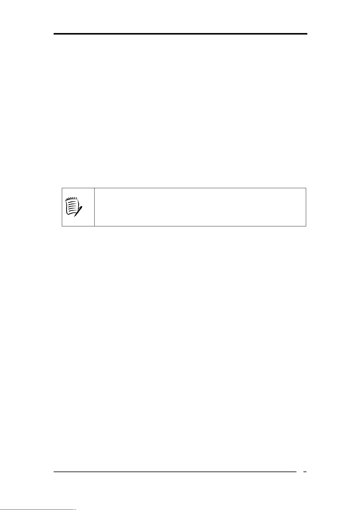
1-3 Back Panel
Printer Port
S1689
PS/2
Mouse
Chapter 1
RJ-45 port
Line-In port
Line-Out port
Microphone
port
PS/2
Keyboard
Serial ports
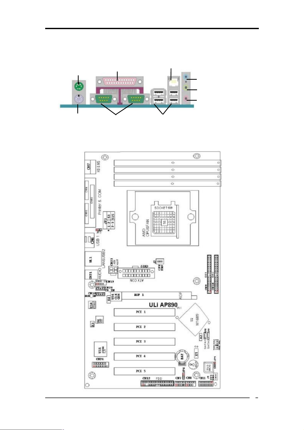
1-4 Motherboard Layout
USB 2.0 ports
3
Chapter 2
Chapter 2 Hardware Setup
2-1 PC D.I.Y. Assembly Instructions
1. Jumper Setting:
Set the CPU External Clock, Frequency Ratio and the CPU voltage according to the
instruction printed on the manual or silkscreen printed on the mainboard.
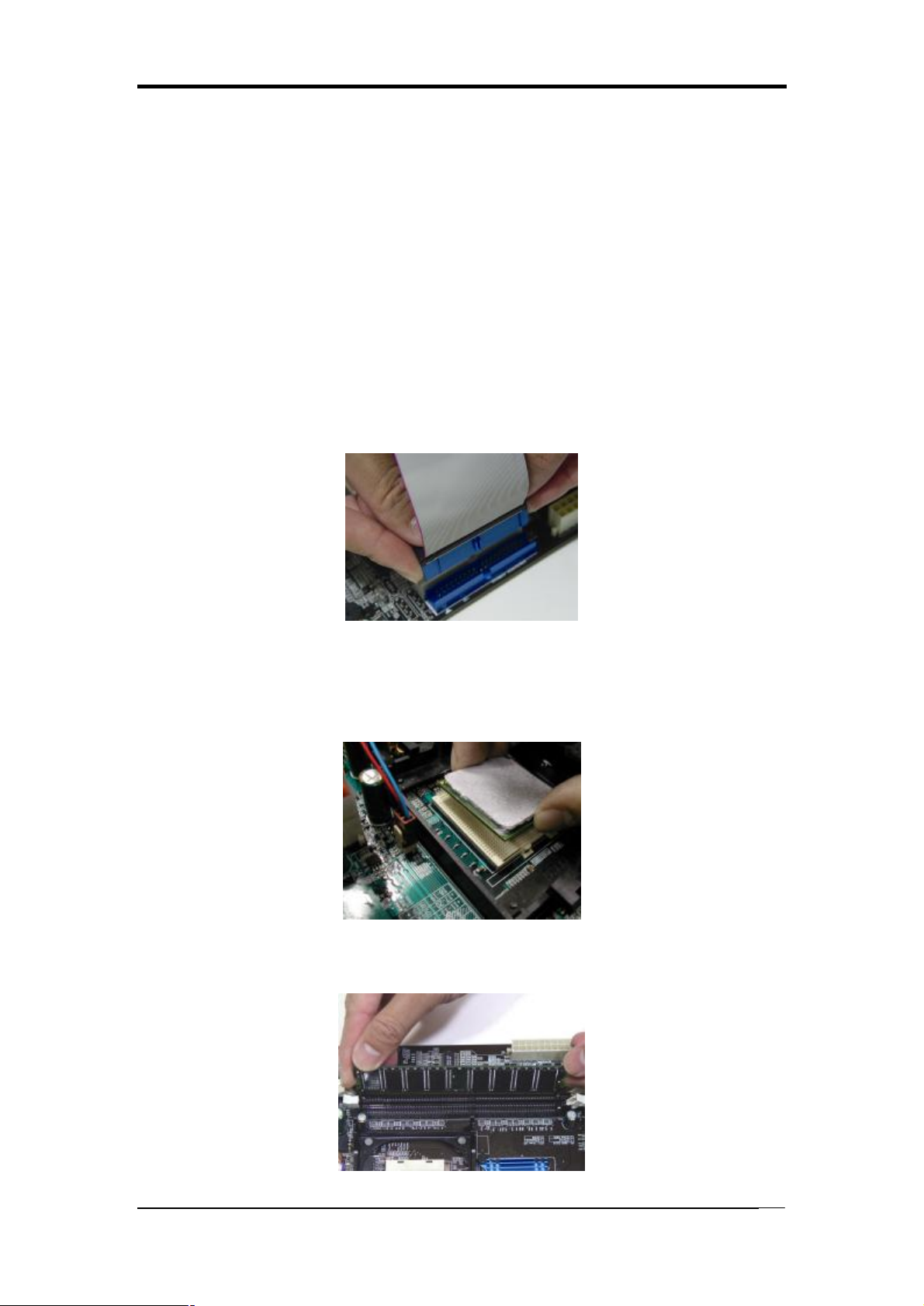
2. Installing FDD and IDE devices:
Aligned the red colored edge of the cable with the pin 1 of the drive connector on the
mainboard and gently attached it. Attach the other end of the cable by aligning the
colored edge to the pin 1 of the device connector. Make sure that all drives are
securely fastened.
3. Installing a CPU:
Locate a noticeable notch in the CPU’s corner. This marking indicate Pin 1 of the
CPU. Gently insert the CPU with Pin 1 at the same corner of the socket that contains
the end of the lever.
4. Installing System Memory:
Push module downward until side clips are properly secure to the module.
4
Chapter 2
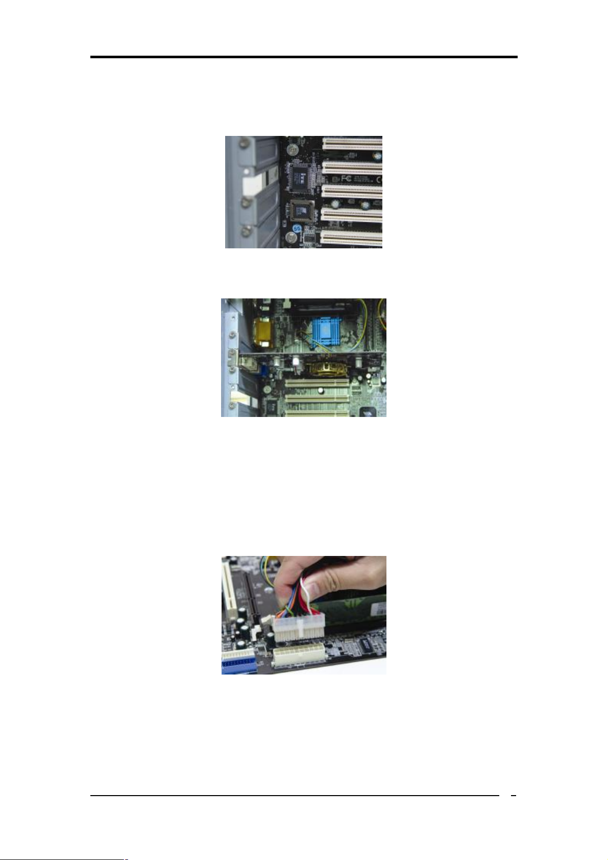
5. Mounting a Mainboard into a Chassis:
Use standoffs and screws to securely mount the mainboard and make sure that all the
mounting holes are properly screwed.
6. Adding an expansion card:
Gently fasten the card to the proper slot.
7. Connecting I/O ports and device connectors:
Simply plug the cable into the respective device port or connector as shown in the
manual or silkscreen printed on the mainboard.
8. Connecting the Power Supply Cables:
Plug in the ATX power cable to the mainboard’s power connector and make sure the
cable is connected.
5
 Loading...