

Sleipner Motor AS RCT2 Users manual
EN
Installation & User Manual
Radio Remote v1.0.1
RC-20U RC-21U RC-22U RC-23U
SLEIPNER MOTOR AS
P.O. Box 519
N-1612 Fredrikstad
Norway
www.side-power.com
©
Sleipner Motor AS 2018
Made in Norway

Contents
Model range................................................................................................................................ 2
Technical specications .............................................................................................................. 3
Important precautions ................................................................................................................. 3
Receiver installation ................................................................................................................... 4
User precautions ........................................................................................................................ 6
How to use RC-20U..................................................................................................................... 7
How to use RC-21U..................................................................................................................... 8
How to use RC-22U..................................................................................................................... 9
How to use RC-23U................................................................................................................... 10
Transmitter LED operation and alarm indication ....................................................................... 12
Electric diagram ......................................................................................................................... 13
Output signals diagram.............................................................................................................. 14
Programming additional transmitters/remote controls ............................................................... 15
Replacing transmitter battery.................................................................................................... 16
Dimensions .............................................................................................................................. 17
Safety Information ................................................................................................................... 18
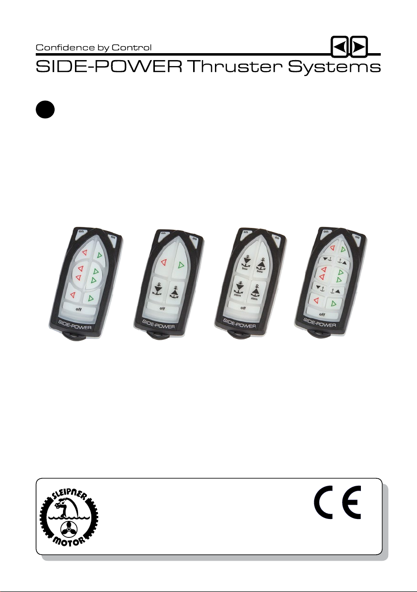
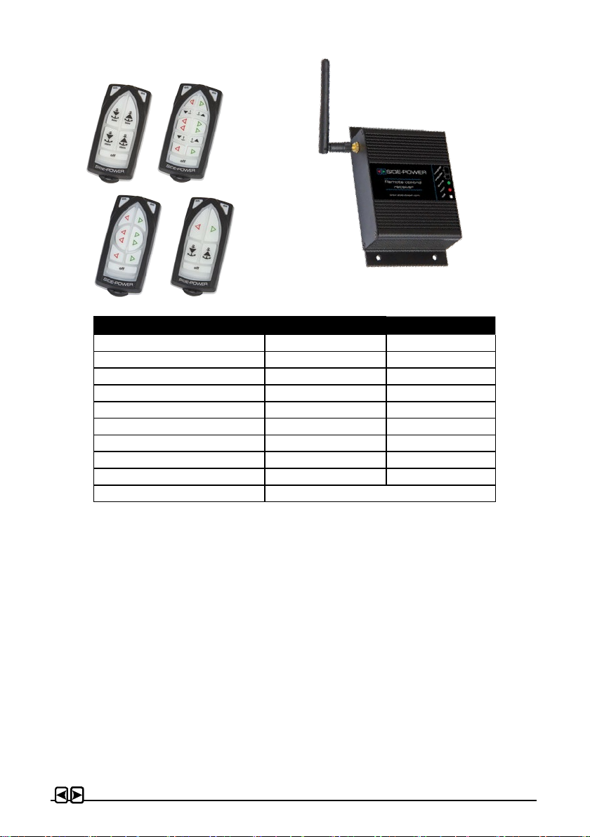
Model range
The radio remote control can control a single bow thruster/windlass or a bow and stern thruster/
windlass combined. The receiver can receive the signals of up to four transmitters/remote controls.
Remote control kit RC-20U consists of:
- Receiver: Part no. RCR-2U
- Transmitter (incl. battery): Part no. RCT-20U
- Holding bracket for transmitter unit: Part no. RC-HOLDER
Remote control kit RC-21U consists of:
- Receiver: Part no. RCR-2U
- Transmitter (incl. battery): Part no. RCT-21U
- Holding bracket for transmitter unit: Part no. RC-HOLDER
Remote control kit RC-22U consists of:
- Receiver: Part no. RCR-2U
- Transmitter (incl. battery): Part no. RCT-22U
- Holding bracket for transmitter unit: Part no. RC-HOLDER
Remote control kit RC-23U consists of:
- Receiver: Part no. RCR-2U
- Transmitter (incl. battery): Part no. RCT-23U
- Holding bracket for transmitter unit: Part no. RC-HOLDER
Additional transmitters/remote controls can be ordered separately;
The transmitter and the receiver have the same factory preset code so no programming is necessary. The battery is already inserted in the transmitter.
When additional transmitters/remote controls are to be used, the new transmitter(s) must be
paired with the receiver (please see programming section).
We Sleipner Motor AS declare that this
device complies with health and safety
requirements according to the Directives
EN301 489-3 V1.4.1:2002
EN301 489-1 V1.4.1:2008
IEC 60533:1999
EN300 220-1 V2.3.1:2010
EN300 220-2 V2.3.1:2010
Installation & User Manual, Radio Remote rev 1_0_1 Page 2
Technical specications
Power feed
Frequency (MHz)
RF-power
Operation temp.
HxWxD (mm)
Weight (g)
Voltage
Standby power
Load, max
Operating range
Transmitter Receiver
1x3V battery (type: CR2032) 12V or 24V power source
914-917 MHz 914-917 MHz
<10mW <10mW
-10°C / +55°C -15°C / +55°C
107x47x21 83x136x36
60 275
8-30V
<300mW
4A
30m under normal operating conditions
Important precautions
• With the boat on land, only run the thruster for a fraction of a second, as without resistance it
will accelerate very fast to a damaging rpm.
• This manual is intended to support educated / experienced sta.
• When installed in boats approved or classied according to international or special national
rules, the installer is responsible for following the demands in accordance with these regula-
tions / classication rules. The instructions in this guide can not be guaranteed to comply with
all dierent regulations / classication rules.
• The transmitter and the receiver have the same factory preset code so no programming is
necessary. When additional transmitters/remote controls are to be used, follow the instructions
in the programming section on page 15.
Compass safe distance:
- RCT-2xxU: 0,3m
- RCR-2U: 0,2m
Installation & User Manual, Radio Remote rev 1_0_1 Page 3

Receiver installation
Prior to installation, it is important that the responsible installer reads this guide to ensure
necessary acquaintance with this product.
WARNING!
WARNING!
Remote receiver power supply negative lead must be connected to the thrusters`s
negative lead. Bow and stern thruster must have common negative. Power to the
thruster’s must be switched o during installation!
• Install the receiver minimum 1 meter (3ft) from high power cables and data communication
cables or other sources of electrical interference, i.e. navigation instruments, radio communication devices, electric motors and generators.
• Install the receiver minimum 1 meter (3ft) above sea level.
• Install the receiver outside of shielded areas for radio signals, i.e. boxes made of metals or
other material with shielding properties.
• Install the receiver in a dry environment, where no condensation can enter the unit. (The
receiver assembly is not waterproof.).
• Mount the receiver using the four holes (please see picture on page 5).
• The receiver must have a separate power supply tted with a 5 Amp fuse in the positive lead
that has either a separate power switch or is shut of by the thrusters system main power
switch. The receiver can not be powered by the thrusters/windlass control looms even if you
nd positive and negative lead there.
• Connect the supplied wiring harnesses to the receiver unit according to the wiring diagram
on page 13. Connect thrusters and windalsses to the appropirate connectors according to
diagram.
• For use with other windlass brands, connections must be determined by the installer according
to output signals diagram on page 14.
NB: Max. load on the windlass signal output is 4A!
If the windlass requires more than 4A, use extra control relay.
Note! Faulty installation will render all warranty given by Sleipner Motor AS void.
Installation & User Manual, Radio Remote rev 1_0_1 Page 4
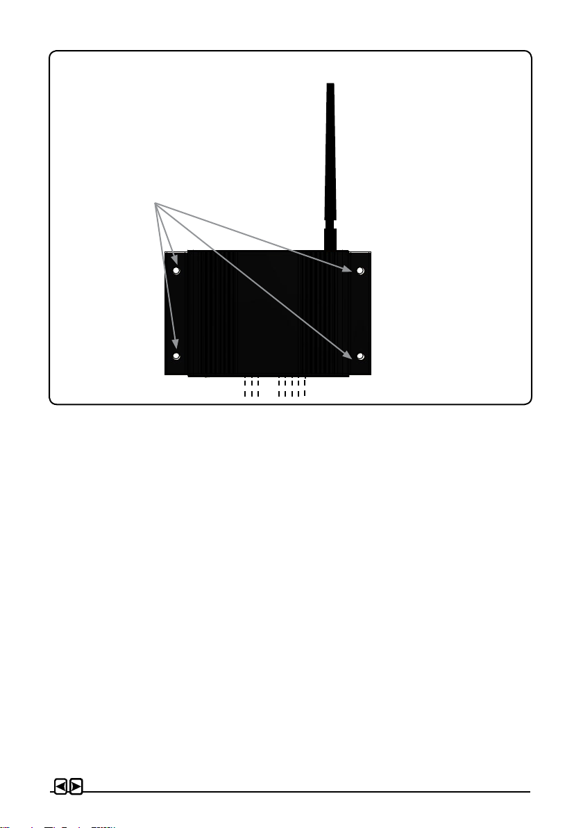
Mount the receiver by using
1
2
3
4
5
the 4 holes.
Installation & User Manual, Radio Remote rev 1_0_1 Page 5

User precautions
• Ensure that you know the location of the main battery switch that disonnects the thruster from
all power sources (batteries) so that the thruster/windlass can be turned o in case of a mal-
function.
• The maximum continues usage time of the electrical thruster is approx. 3 minutes. The electro
motor has a built in thermal cut-o switch that will shut it o when overheating and re-engage it
when it has cooled down some. This should be considered when planning your manouvering.
• Never use a thruster close to somebody in the water, as the thruster will draw objects close by
into the tunnel and contact with the rotating propellers will cause serious injuries.
• Never use a windlass close to somebody in the water, an unexpectedly drop of the anchor can
cuse serious injuries.
• If the thruster stops giving thrust while the electric motor is running, chances are that there is a
problem in the drive-system. You must then immediately stop trying to run it, and turn it o, as
running the electricmotor for more than a few seconds without resistance from the propeller,
can cause serious damage to the electricmotor.
• When leaving the boat always turn o the main power switch for the thruster/windlass and turn
o the power to the receiver.
• We advice to always keep the main engine(s) running while using a thruster/windlass. This
will keep the batteries in a good charge condition. This will also give better performance to the
thruster.
• It is the owner/captain/other responsible party full responsibility to assess the risk of any
unexpected incidents on the vessel. If the thruster stops giving thrust for some reason while
maneuvering you must have considered a plan on how to avoid damage to persons or other
objects.
Installation & User Manual, Radio Remote rev 1_0_1 Page 6
 Loading...