

Page 1

Installation Guide
For DC External POD Electric Thruster Models
SX35POD, SX50POD
SLEIPNER AS
P.O. Box 519
N-1612 Fredrikstad
Norway
www.sleipnergroup.com
DOCUMENT ID:
REVISION:
DATE:
LANGUAGE:
6398
11
2 0 21
I M
EN
Page 2

Contents
Installation Manual
Responsibility of the Installer ...............................................................................................................................................................3 - 4
Thruster Measurements ............................................................................................................................................................................ 5
Thruster Specications............................................................................................................................................................................... 6
Technical Specications ............................................................................................................................................................................ 6
Control Box Technical Specications ......................................................................................................................................................... 7
Positioning of the SX with Hydrodynamical Cover ..................................................................................................................................... 8
Grids or Cowls Assembly ............................................................................................................................................................................ 9
Tunnel Installation ................................................................................................................................................................................... 10
Hydro pod Modication ........................................................................................................................................................................... 11
Hydro pod Installation ............................................................................................................................................................................. 12
Propeller Installation ............................................................................................................................................................................... 13
Control Box Installation........................................................................................................................................................................... 14
Thruster Electrical Installation......................................................................................................................................................... 15 - 16
Electrical Specications ......................................................................................................................................................................... 17
Control Panel Cable Installation ............................................................................................................................................................ 18
Control Panel Installation ....................................................................................................................................................................... 19
Pre-delivery Checklist ............................................................................................................................................................................ 20
Service and Support .......................................................................................................................................................... 21
Product Spare Parts and Additional Resources ................................................................................................................... 21
Warranty Statement .......................................................................................................................................................... 21
Products
SM150536 | SXPOD-35/50-50MM - Hydropod complete kit for in water flow conguration
Sleipner Motor AS
P.O. Box 519, Arne Svendsensgt. 6-8
N-1612 Fredrikstad, Norway
MC_0020
-
2
HydroPOD 35 & 50
6398
11 2 0 21
Page 3

Failure to follow the considerations and precautions can cause serious injury,
damage and will render all warranties given by Sleipner Motor as VOID.
MC_0411
Responsibility of the Installer
The installer must read this document to ensure necessary familiarity with the product before installation.
Instructions in this document cannot be guaranteed to comply with all international and national regulations. It is the responsibility of the
installer to follow all applicable international and national regulations when installing Sleipner products.
The recommendations given in this document are guidelines ONLY, and Sleipner strongly recommends that advice is obtained from a person
familiar with the particular vessel and applicable regulations.
This document contains general installation instructions intended to support experienced installers. If you are not skilled in this type of work,
please contact professional installers for assistance.
If required by local regulation, electrical work must be done by a licensed professional.
Appropriate health and safety procedures must be followed during installation.
Faulty installation of Sleipner products will render all warranties given by Sleipner Motor AS.
General Installation Considerations and Precautions for Thrusters
• Do not install the thruster in a position where you need to cut a stiffener/ stringer/ support that may jeopardise the hull integrity without checking
with the boat builder this can be done safely.
• We advise painting the gear house and propellers with anti-fouling. (NB: Do not paint the anodes, sealing, rubber fi ttings or propeller shafts)
• Do not nish the inside of the tunnel with a layer of gel-coat/ topcoat or similar. There is only room for a thin coat of primer and two layers of anti-
fouling between the tunnel and the props.
• Never run the thruster out of water.
• The electro/ hydrulic motor must be handled with care. Do not place down the motor on the drive shaft.
MC_0038
MC_0425
General Installation Considerations and Precautions for Electric Thrusters
• The thruster must NOT be installed in compartments that require ignition proof electric equipment. If necessary, make a separate compartment.
(NB: Ignition Protected systems are tested to be installed in areas with possible explosive gases in accordance with ISO 8846)
• When installing the thruster electro motor in small compartments, ensure the compartment is well ventilated to allow for cooling of the electro
motor.
• If the height of the room you are installing the thruster is limited, the thruster can be installed horizontally or at any angle in-between.
- If the electro motor is positioned more than 30 degrees off vertical, it must be supported separately.
- Beware of keeping installation within advised measurements. No part of the propeller or gear house must be outside the tunnel.
• Do not install the thruster in a position where you need to cut a stiffener/ stringer/ support that may jeopardise the hull integrity without checking
with the boat builder this can be done safely.
• The electro motor, components and cables must be mounted so they remain dry at all times.
• We advise painting the gear house and propellers with anti-fouling. (NB: Do not paint the anodes, sealing, rubber fi ttings or propeller shafts)
• Do not nish the inside of the tunnel with a layer of gel-coat/ topcoat or similar. There is only room for a thin coat of primer and two layers of anti-
fouling between the tunnel and the props.
• Don’t install the electro motor close to easily flammable objects or equipment as it will reach over 100°C before the temperature switch is activated.
• Do not store items close to the thruster motor. Any loose items near the thruster motor is a potential re hazard and can cause undesired short-
circuiting.
• Do not lift it by internal cable connections, main terminals.
• The thruster power supply circuit must include the recommended sized fuse and a battery isolation switch.
MC_0031
General Installation Considerations and Precautions for DC Electric Motors
• The electro motor will generate some carbon dust so any storage compartments must be separated from the thruster to prevent nearby items
becoming dusty/ dirty. (NB: IP version motors generate dust but are enclosed.)
-
HydroPOD 35 & 50
6398
11 2 0 21
MC_0426
3
Page 4

MG_0080
H
+H
L
W
WD
MC_0268
Thruster Measurements
Measurement
code
Measurement description
mm inch mm inch
H Mould Height 180 7,08 180 7,08
+H Tube Height 183 7,20 183 7,20
W Width 183 7,2 183 7,2
L Length 630 24,8 630 24,8
*35
12v
*50
12v
*Valid for SX & SXP
Failure to follow the considerations and precautions can cause serious injury,
damage and will render all warranties given by Sleipner Motor as VOID.
• The external thruster assembly and controller unit are ignition protected and can be installed in areas with the chance of explosive gases in
accordance to ISO 8846 and ABYC c1500. (Certi cation pending)
• Ensure that the external thruster assembly does not disturb the water flow under the hull. At higher speeds, if the thruster is installed to
low it can cause damage to the thruster and/ or add additional drag and unwanted water splashing.
• The recommended minimum tunnel depth from the water surface is 140mm (5,51‘) to the centre of tunnel diameter. Place the Thruster as deep as
possible for better performance and reduced noise.
• When installing the thruster ensure it does not foul existing equipment inside the boat like motor bedding etc.
• If able ensure that stern-drives/ trim-tabs do not interfere with the water flow from the thruster as this can reduce the thrust effectiveness
considerably. We recommend the use of our Sleipner cowls to enhance the performance and allow installation in shallow draft boats. Sleipner
cowls will also minimise the effect if stern-drives/ trim-tabs obstruct the thruster.
• Ensure there is enough space both inside and outside the transom of the boat and the thruster does not get in conflict with existing equipment
inside the boat like steerage links etc. (NB: It is possible to mount the tunnel offset from the boat’s centre line if necessary.)
• Heat protection cut off is calculated from the thruster motor. To avoid cable overheating do not install place the volt cables from the thruster to the
control box near any heat sources.
General Installation Considerations and Precautions for SX Thrusters
MC_0411
MC_0427
General User Considerations and Precautions for IP Systems
NEVER Disassemble any part of the Ignition Protected assembly. Tampering with the Ignition Protected assembly will cause it to lose this
safety feature. If there is a problem with your Ignition Protected motor, please contact your dealer.
MC_0007
-
4
HydroPOD 35 & 50
6398
11 2 0 21
Page 5
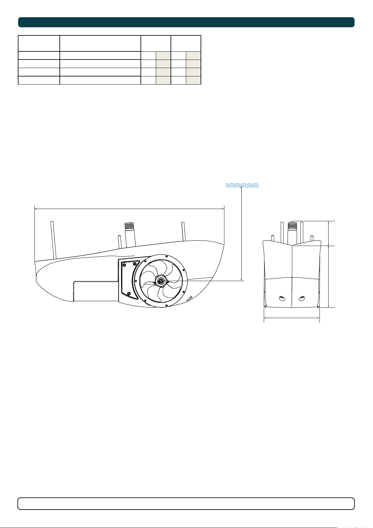
Thruster Measurements
MC_0268
Measurement
code
H Mould Height 180 7,08 180 7,08
+H Tube Height 183 7,20 183 7,20
W Width 183 7,2 183 7,2
L Length 630 24,8 630 24,8
*Valid for SX & SXP
Measurement description
L
*35
12v
mm inch mm inch
*50
12v
WD
+H
H
W
MG_0080
HydroPOD 35 & 50
6398
-
11 2 0 21
5
Page 6

Thruster Specifi cations
MG_0132
121 mm
4’76”
187 mm
7’36”
170 mm
6’69”
136 mm
5’35”
110 mm
4’33”
Description * 35 * 50
Available DC System (v) 12v 12v
Thrust 12v or 24v (kg * lbs) 43 kg * 94 lbs 62 kg * 136 lbs
Thrust 10.5v or 21v (kg * lbs) 35 kg * 77 lbs 50 kg * 110 lbs
Typical Boat Size (m * ft) 6m - 10m * 19ft - 32ft 8m - 11m * 27ft - 37ft
Propulsion System Single Single
Power (kw * Hp) 1.8kw * 2hp 2.8kw * 3.75hp
Weight (kg * lbs) 19.3 kg * 42.55 lbs 19.3 kg * 42.55 lbs
MC_0306
Technical Specifi cations
Motor: Custom made reversible DC-motor.
Gear house: Seawater resistant aluminium. Ball-bearing and ceramic axial seals at propeller shaft and a combination of ball bearing/ slide
bearing at drive shaft. (Pre- lled and sealed for life)
Motor bracket: Seawater resistant aluminium, galvanization insulated from the motor.
Tunnel: Hydrodynamic breglass reinforced snap on composite.
Propeller: 5-blade skewback “Q-prop” propeller, breglass reinforced composite.
Batteries: Minimum recommended battery capacity (cold crank capacity by DIN/SAE standard)
Contact a battery supplier for more information.
Max. Use: 2 - 3 min. duty cycle at 20°
Safety features: - Electronic time-lapse device protects against sudden change of drive direction.
- The electric thermal cut-off switch in electro motor protects against overheating (auto-reset when electro motor cools down).
- Original Sleipner panels shut off automatically 6 minutes after last use.
- Original SLeipner panels use child-safe double ON buttons.
- An integrated microprocessor monitors solenoids, reduce wear and risk of solenoid lock-in.
- Auto-stop of the thruster occurs when an undesirable solenoid lock-in occurs or when continuous operation cut-off timer
exceeds 3 minutes.
MC_0073
-
6
HydroPOD 35 & 50
6398
11 2 0 21
Page 7
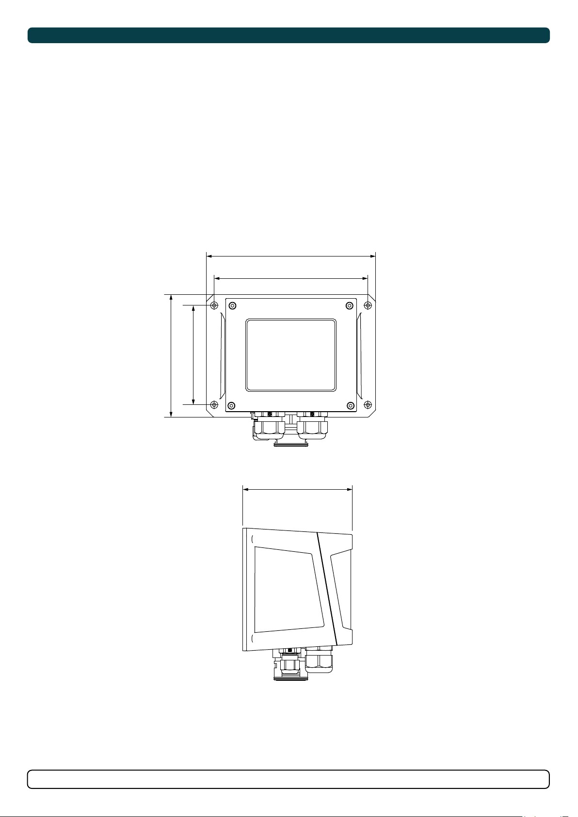
Control Box Technical Specifi cations
SX35 SX50
Operation volts: 12v. 12v
Max Current: 250A 380A
Duty Cycle: S2. S2
Max ambient temp: 50ºc 50ºc
Min ambient temp: -25ºc -25ºc
Power supply cable: 35 - 70mm²/ AWG 2 - 00 35 - 70mm²/ AWG 2 - 00
Mount direction : Any Any
187 mm
7’36”
170 mm
6’69”
MC_0082
136 mm
5’35”
110 mm
4’33”
121 mm
4’76”
HydroPOD 35 & 50
6398
-
11 2 0 21
MG_0132
7
Page 8
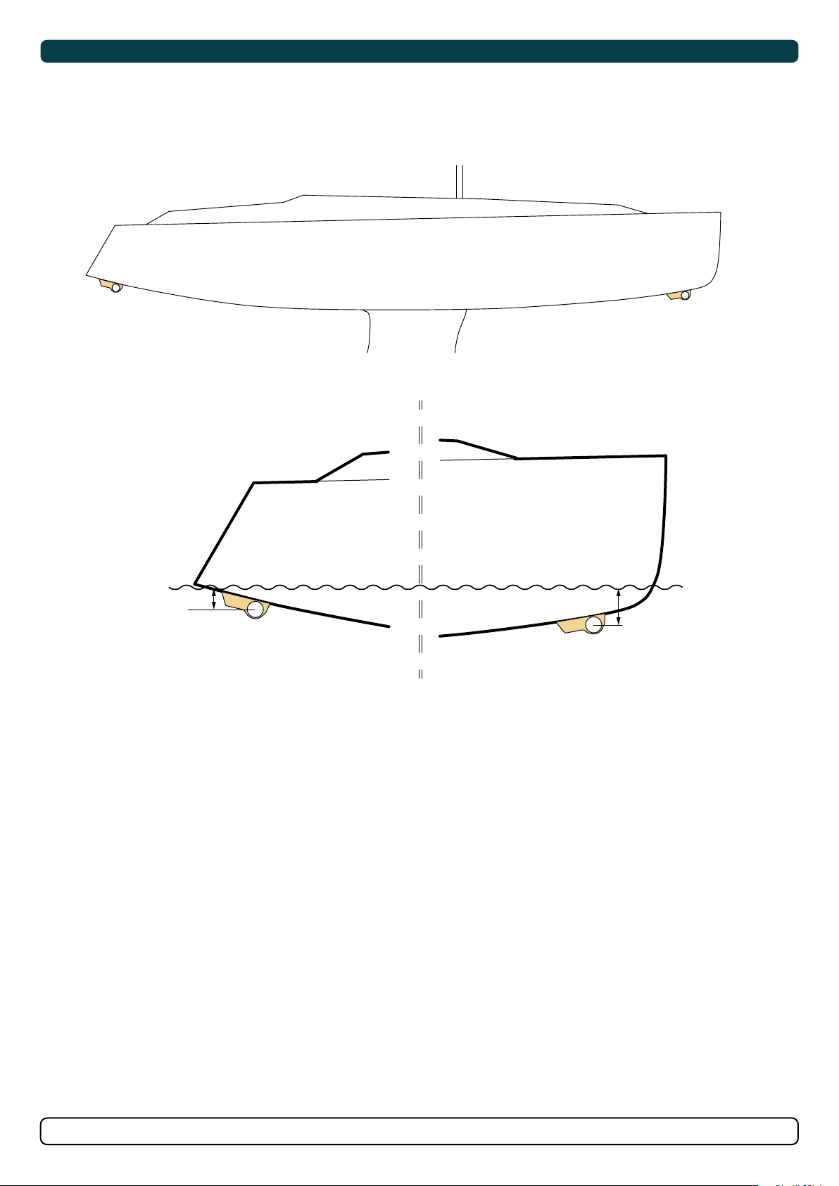
Positioning of the SX with Hydrodynamical Cover
Aim to install the thruster as far forward/ Aft as possible
Due to the leverage effect around the boats’ pivot point. The relative distance difference from the boat pivots’ point to the thruster will determine the
amount of real thrust for the boats, rotation.
MC_0072
STERN BOW
MG_0162
-
8
HydroPOD 35 & 50
6398
11 2 0 21
Page 9
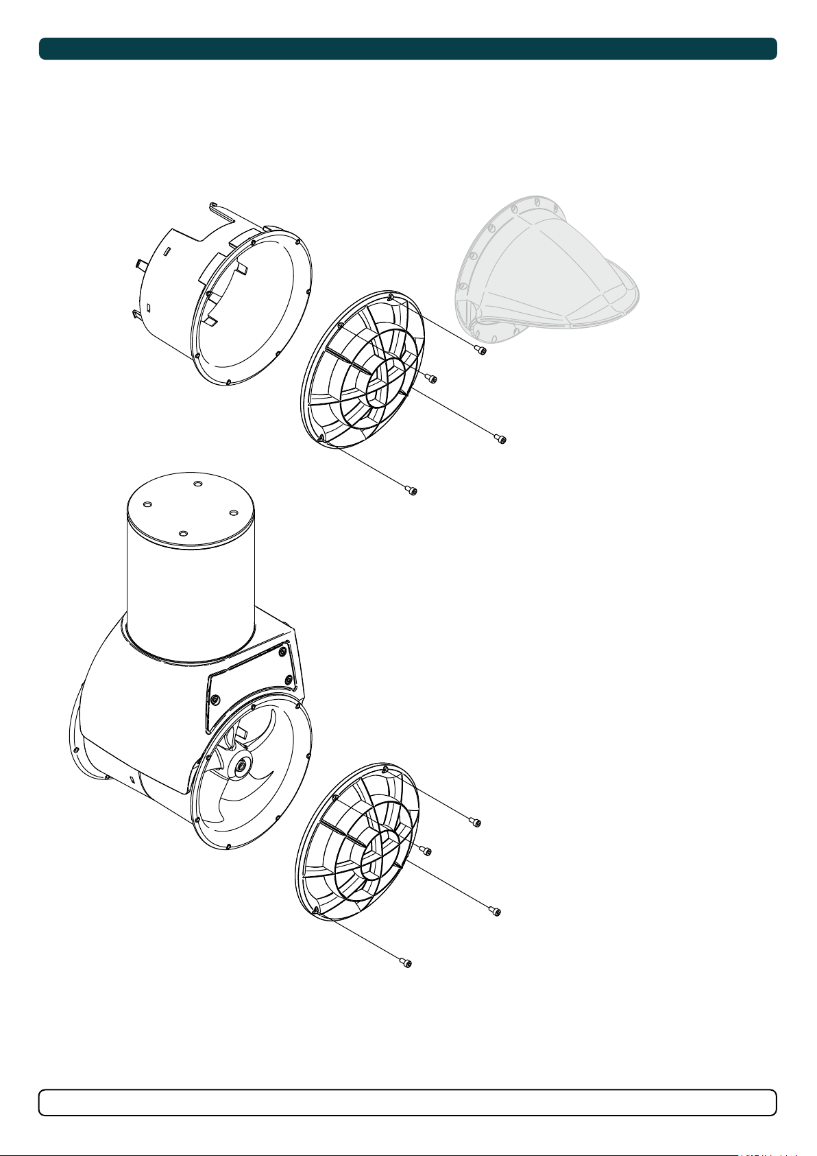
Grids or Cowls assembly
1. Attach the cowls or grids with included bolts and washers. (NB: If installation of the cowls ensure the appropriate twist of the cowl to direct water
away from obstacles)
*Cowl
MC_0074
Tighten 2Nm
MG_0145
Tighten 2Nm
HydroPOD 35 & 50
6398
-
11 2 0 21
9
Page 10
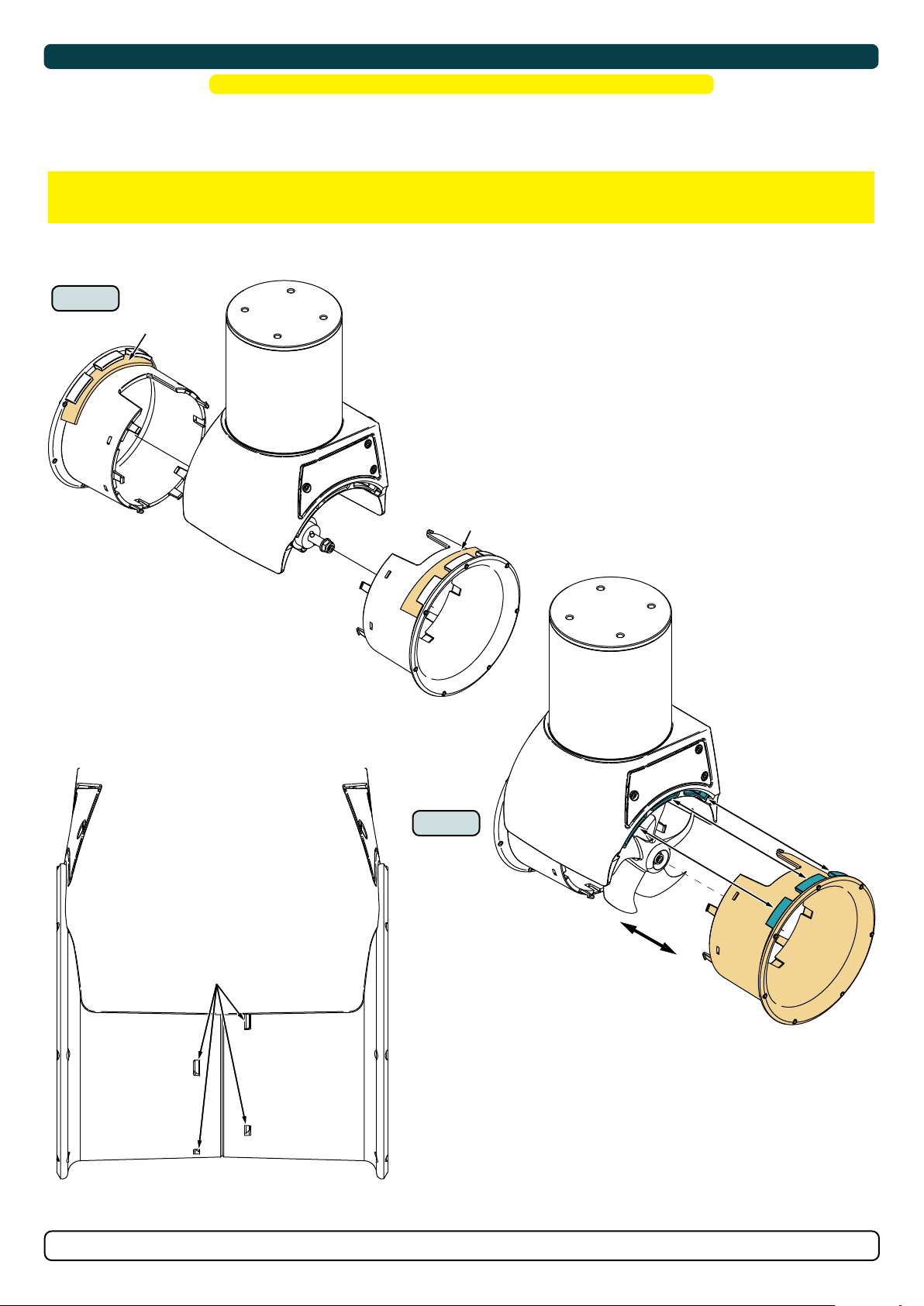
Tunnel Installation
! Please refer to the graphic for special considerations relating to your model !
1. Ensure to remove the plastic cover guard on the tunnel.
2. Connect both ends of the tunnel to the thruster motor. All hooks must be completely interlocked making the inside of the tunnel smooth. (NB:
Ensure tunnel moulding around the gear leg and tunnel top align.)
IMPORTANT
Ensure all snap-lock positions are correctly connected into place.
MC_0074
1
Remove cover
guard.
Align two ends of the tunnel.
Remove cover guard.
Remove cover
guard.
Snap lock
2
Check snap lock
positions around the
tunnel.
Ensure top lips tabs
into the motor
inserts.
Push two tunnel
ends together.
MG_0112
10
HydroPOD 35 & 50
6398
-
11 2 0 21
Page 11
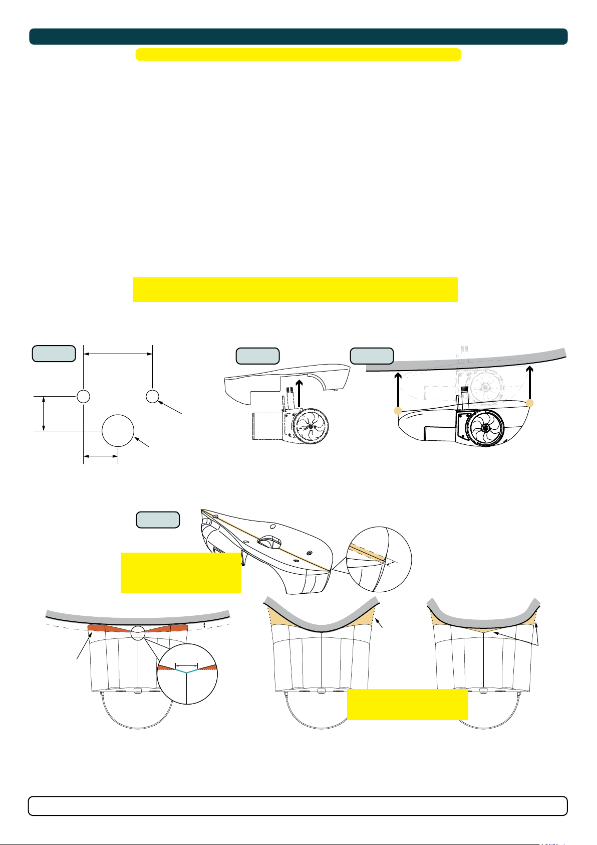
Hydropod Modifi cation
! Please refer to the graphic for special considerations relating to your model !
De ne the location to install the thruster. (NB: Ensure internally the thruster will not obstruct any objects. Ensure cables internally do not
obstruct any objects. Do not place cables or control box close to high heat radiating parts EG. Turbo/ exhaust manifolds etc.)
1. Mark the locations of the three drill holes for the SX thruster using the de ned measurements or from a template to the hull. (NB: Maximum hull
thickness is 50mm.)
2. Drill main hole for the cable tube, then two support bolt holes.
3. Place the SX thruster into the Hydro pod mould.
4. Place the hydro-pod with the SX thruster on the hull. Use the pre-drilled holes to guide the assembly to the desired location. (NB: The SX thruster
in the Hydro pod will ensure no flexing of the mould will occur)
5. Modify the Hydro pod mould to match the hull pro le of the boat. Aim to obtain both the front and back tips of the mould sit flush to the hull.
Follow the below instructions depending on the modi cation required:
A) Trim the wings of the hydro pod to match the hull pro le. (NB: Excessive heat caused by the cutting method can cause the mould to melt in
the worked area.)
OR
B) Determine to use appropriate ller to ll the gap between the hydro pod and the hull. (NB: Do not fi ll gaps at this stage if required.)
IMPORTANT
Do not trim past/off the end grooves or centre groove line at a distance of 5mm.
MC_0269
1 - 2
Hole size
for hull
35,80 mm
1,41”
Drill holes in hull
Hull profile
Remove from
wing area
65 mm
2,56”
130 mm
5,12”
18 mm
0,71”
50 mm
1,97”
5
IMPORTANT
Do not trim past/off the end
grooves or centre groove line at
a distance of 5mm.
Hull
Clearance
gap
3 4
Hull
OR
Hull
Fill from
wing area
Fill area
HydroPOD 35 & 50
Do not fill gaps at this stage if
IMPORTANT
required.
6398
-
11 2 0 21
MG_0314
11
Page 12
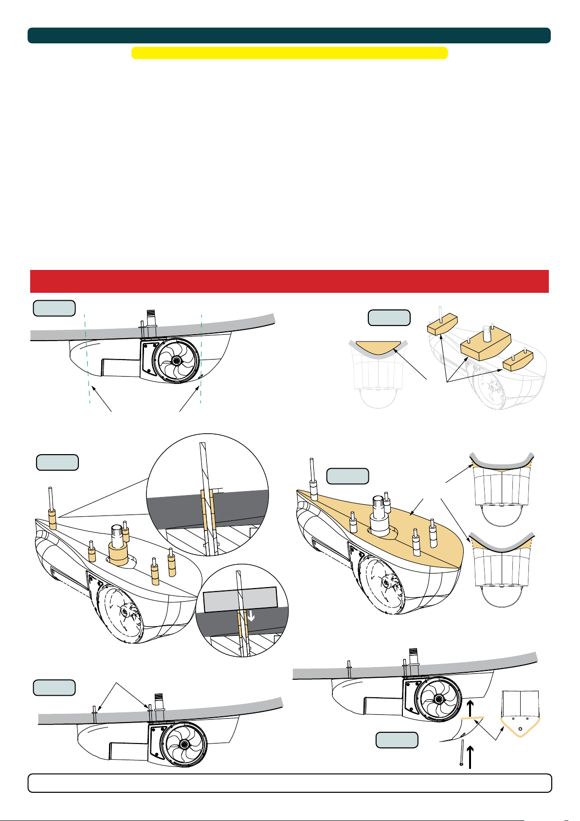
Hydropod Installation
! Please refer to the graphic for special considerations relating to your model !
1. Temporally fasten the Hydro pod to the hull using the SX thruster bolts. Mark the remaining Hydro pod holes (1 rear, 2 front) and drill holes.
Clean the area from dust for installation of the thruster. (NB: Tightening the Hydro pod can reduce the gap between the mould and the hull from
compression. Note this when if required to add MS Polymer to fi ll gaps.)
2. Make support segments based on the hull pro le for the bolt and tube fasteners.
3. Check the length of the compression rings. Compression rings must be longer than hull thickness to allow for compression (NB: Cut compression
sealants to length top achieve 15% compression.)
4. Apply a sealant (MS Polymer) to: IF: required to ll gaps between the Hydro pod and the hull use an
- the inside surface of the cut-out holes on the hull. appropriate amount on the Hydro pod mould to achieve this.
-To the surface of the washer to the thread and
- in the recess of the main tube to the thread.
- 1cm deep inside all compression ring.
place all compression rings to bolt threads.
(NB: Ensure ample sealant (MS Polymer) around the bolts and centre tube for a watertight fi tting.)
5. Place the Hydro pod to the hull without the nose cap. Fasten the Hydro pod via the SX thruster and back hydro pod securing bolt. (NB: Wipe away
MS Polymer that has been pushed out from the compression of the Hydro pod to the hull.)
6. Place the Hydro pod nose cap and fasten nose cap securing bolt
For installations in high corrosive environments (saltwater) the exposed aluminium parts of the thruster must be coated with an epoxy primer
before antifouling or/and use.
MC_0269
1
Mark and drill the remaining Hydropod holes.
(1 rear, 2 front)
3
All rings need
+10% compression
+10%
compression
Hull
2
Support
brace
4
MS
Polymer
12
support
segment
Hull
compression with
support segments
Fasten
5
HydroPOD 35 & 50
6
6398
-
11 2 0 21
MS
Polymer
MG_0314
Page 13
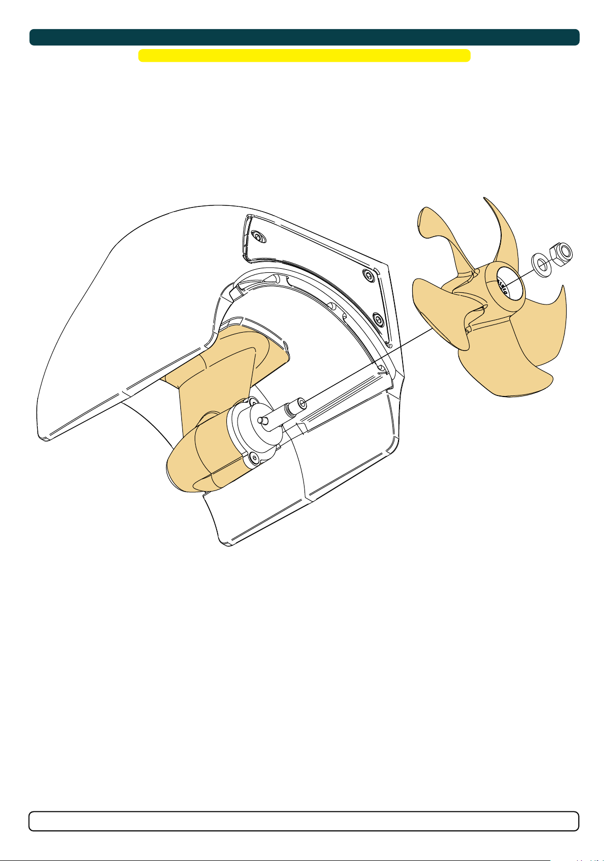
Propeller Installation
! Please refer to the graphic for special considerations relating to your model !
1. Centre the drive pin and Insert the propeller onto the shaft spine. Rotate the propeller until the drive pin aligns with the internal slot in the
propeller.
2. Insert the washer to the end of the shaft spline. Tighten with the propeller lock-nut.
3. Apply anti fouling to the gear leg and propeller. Do not apply anti fouling to any rubber elements of the gear leg or anodes.
MC_0016
HydroPOD 35 & 50
6398
-
11 2 0 21
MG_0478
13
Page 14
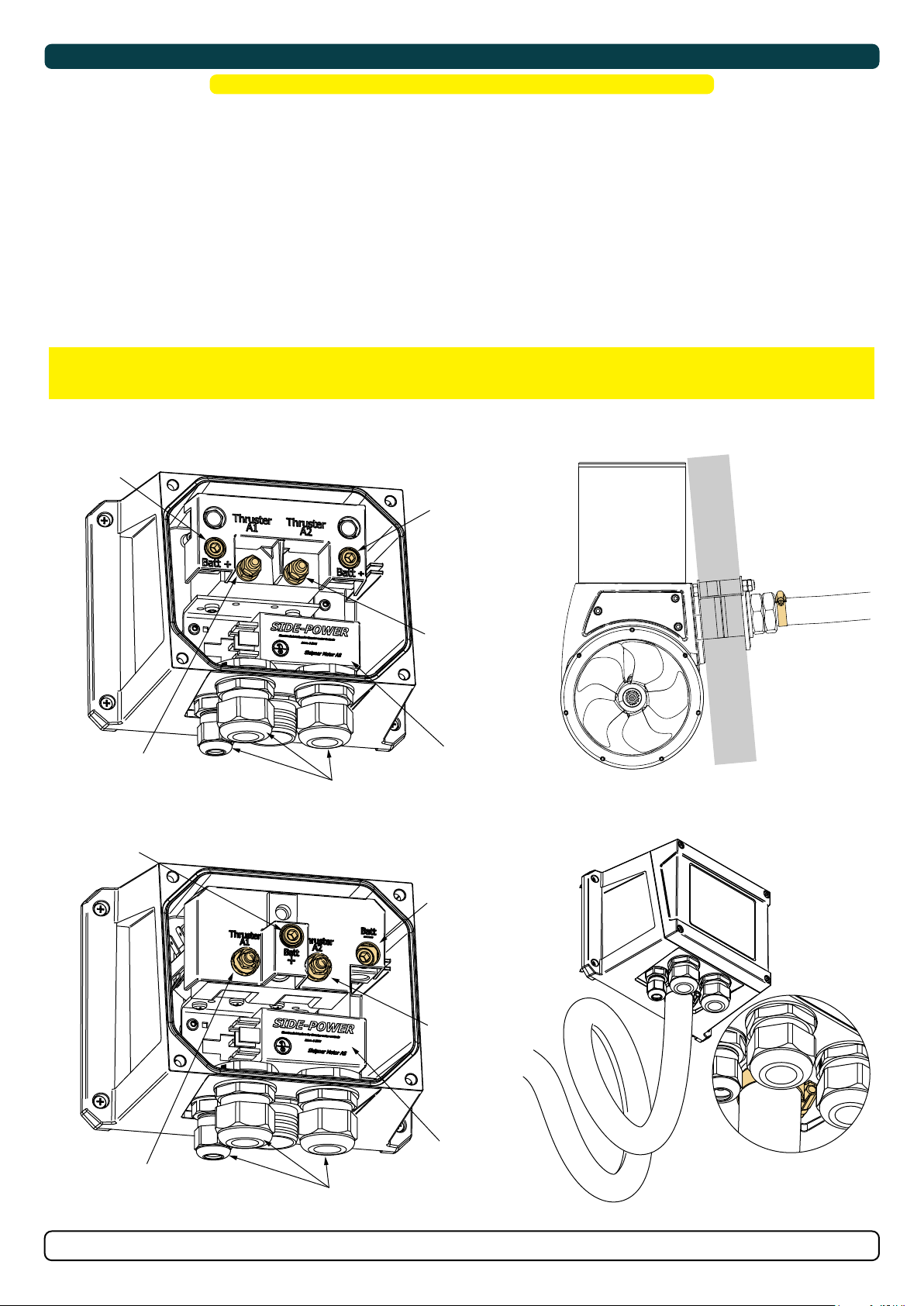
Control Box Installation
! Please refer to the graphic for special considerations relating to your model !
The control box is the central component that can be connected to several other control panels. The control box can be mounted in any orientation,
preferably with cables facing down. (NB: The control box must be positioned within 0,75 meters from the thruster assembly with the provided
cables and not near any object that radiate high temperatures.)
1. De ne the location to install the control box. (NB: Ensure cables will not obstruct any objects.)
2. Mark the locations of the four drill holes and drill the holes.
3. Attach cables to the control box (NB: the control box internal components can be removed via its attachment screws for easier installation
using thick battery cables.)
4. Tighten hose clamps in order to ensure Ignition Protection as illustrated.
5. Fasten the control box to the hull.
IMPORTANT
It is the installers full responsibility to follow instructions and ensure total Ignition Protection.
MC_0075
BAT. +
5.6 Nm
MOTOR CABLE +
4Nm
BAT. +
5.6 Nm
# SX35 CONTROL BOX
BAT. -
5.6 Nm
Hose claps
MOTOR CABLE 4Nm
6 1232i
TORQUE 8Nm
# SX50 CONTROL BOX
BAT. -
5.6 Nm
MOTOR CABLE +
4Nm
14
TORQUE 8Nm
MOTOR CABLE 4Nm
6 1232i
HydroPOD 35 & 50
6398
Control Box
hose clamp
-
11 2 0 21
MG_0114
Page 15
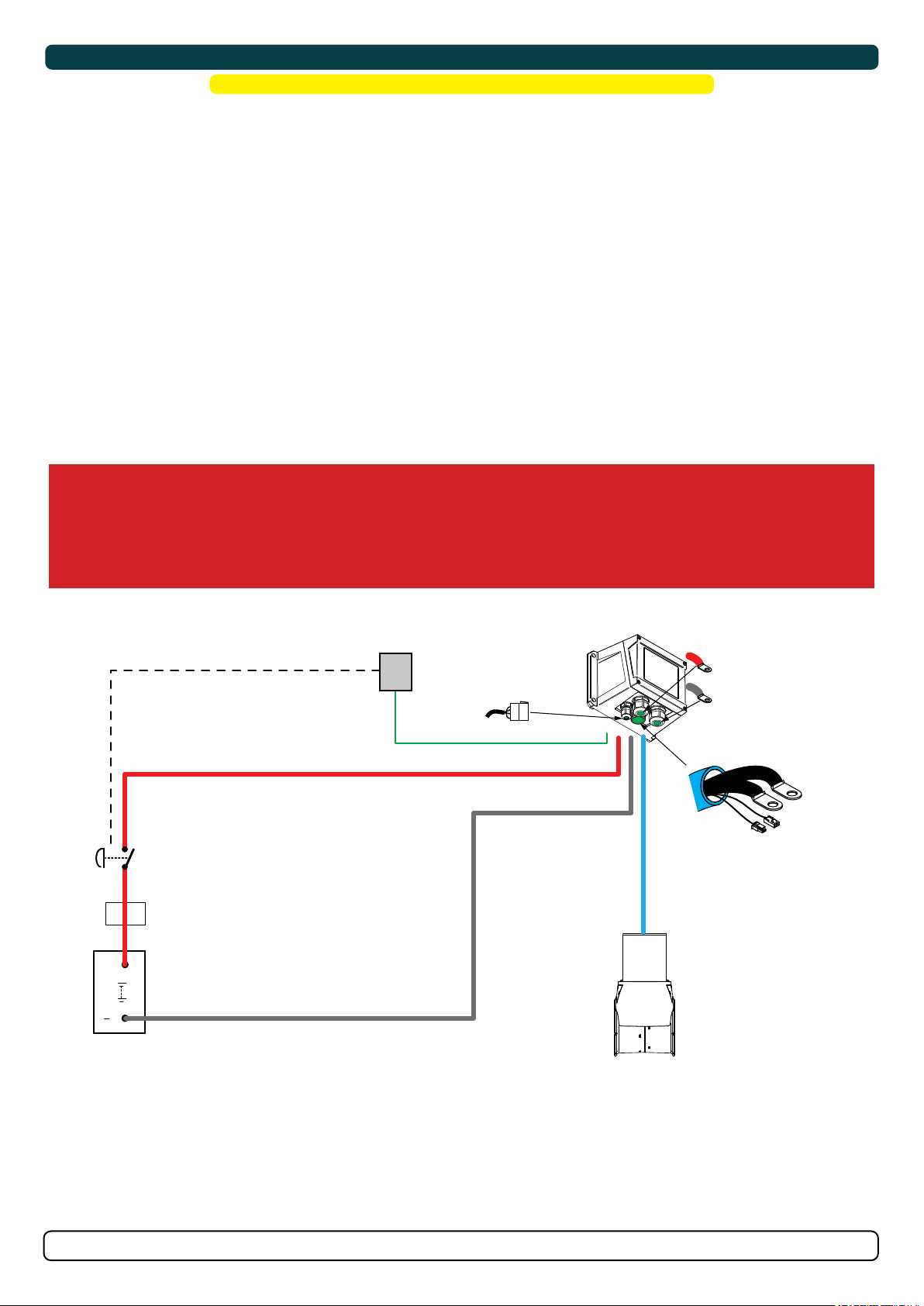
Thruster Electrical Installation
! Please refer to the graphic for special considerations relating to your model !
1. Information of electrical table.
- All power cable lengths represent the total length of the combined (+) and (-) cables.
- Battery capacity is stated as minimum cold crank capacity, (CCA).
- Use slow blow rated fuses to hold stated Amp-Draw for min. 5 minutes.
- Consider the AMP hours (Ah) for your speci c duty cycle.
2. Use appropriate sized cables and batteries with high cranking capacity to feed the thruster. The actual voltage at the motor while running the
thruster decides the motors output RPM and thrust. Use larger cables and stronger batteries for better results.
- See electrical speci cations for advised minimum cables and batteries (CCA).
3. Connect the battery supply to the control unit (PPC).
- Install a main manual/ automatic switch from the positive lead terminal on the battery PPC unit). The main switch must be accessible to turn
off the thruster independently from the rest of the electrical operation of the vessel when not on-board or in emergencies. (NB: It is advised
to install a fuse on the positive cable for protection against short-circuiting of the main cables. The fuse should ensure no voltage
decrease, slow-blow and sized to take the amperage draw for at least 5 minutes.)
- A circuit breaker can be used instead of the fuse and main power switch If the functionality is the same.
(NB: For Ignition Protected installations remember to use ignition protected fuses and switches if fi tted in areas that require this feature.
Ensure to follow your national regulations)
5. Cable lugs must have adequate electrical and mechanical isolation and tted with cable lug covers.
6. Fasten cables to the required torque.
After all electrical connections have been completed check with an ohm meter that there is no electrical connection between
see next page
WARNING
Check the following with the main switch is set to off :
1. electro-motor flange and the positive terminal on the motor
2. electro-motor flange and the battery negative terminal on the motor
MC_0035
*C
Automatic MAIN
SWITCH
*D
MAIN FUSE
++
THRUSTER
BATTERY
12V
To control panel(s)/remote.
B+
**Automatic or
Manual main switch
(See Main Switch
installation manual)
B-
If unsure contact skilled personnel.
Control Cables
CONTROLLER
B+
B-
BLUE PROTECTION
SLEVE
(900mm/ 35”)
A2
A1
Temp switch NC
NTC
THRUSTER
(MUST BE IGNITION PROTECTED IF
LOCATED IN IP REQUESTED AREA)
Minimum and recommended cable dimensions can be identical due to safety margins and cable heat considerations for short cable lengths.
* Minimum or recommended cable cross section in mm2
CONTROLLER CONNECTIONS:
<<B+>>: Power supply pos from thruster battery/ Main switch/ Main fuse
<<B->>: Power supply neg from thruster battery
2 Motor cables from thruster
4 wires from thruster overtemp switch
2 Control cables from control panel(s)/ remote
-
HydroPOD 35 & 50
6398
11 2 0 21
MG_0039
15
Page 16
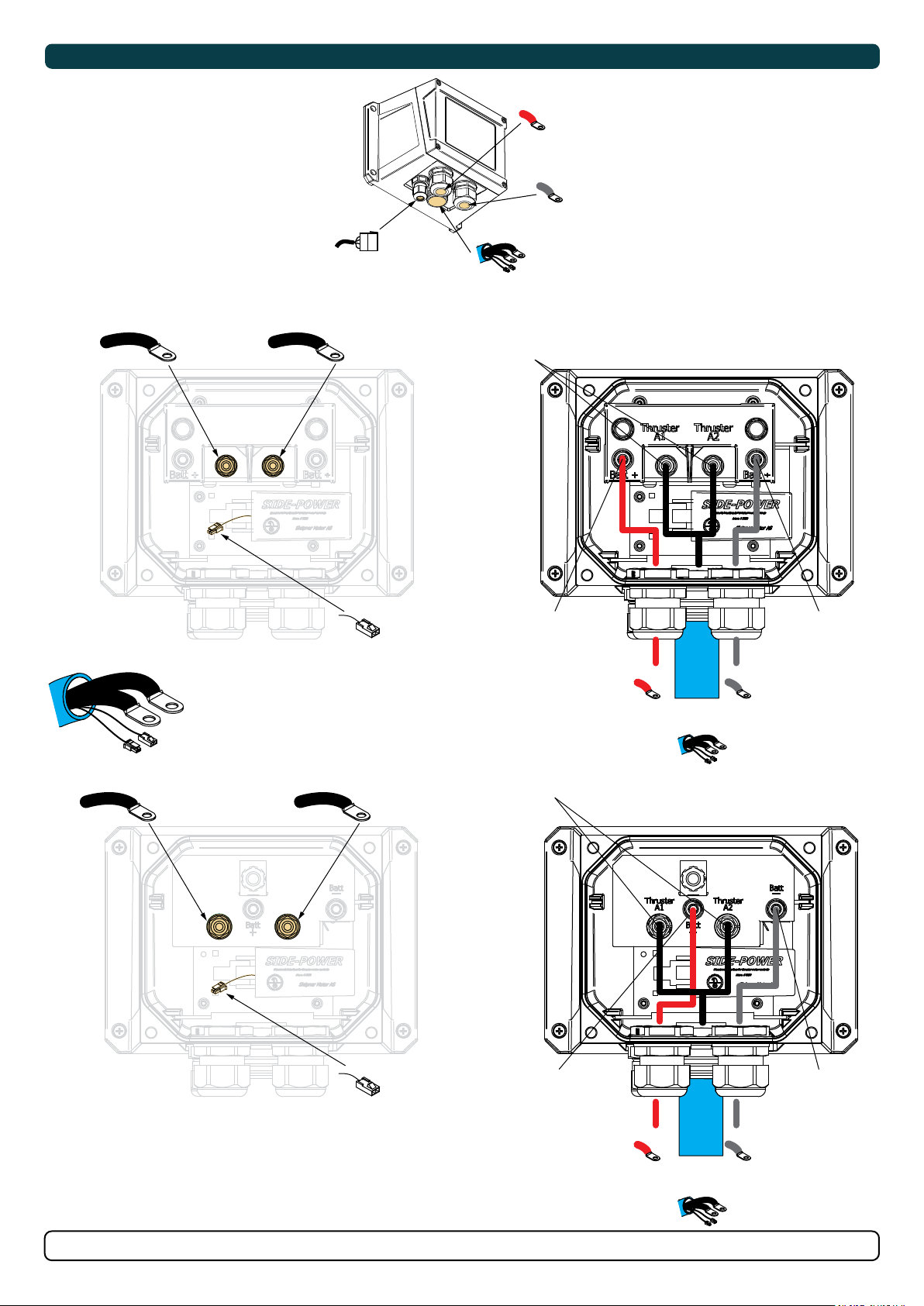
A1
ThrusterA1Thruster
ThrusterA1Thruster
Thruster Electrical Installation
B+
B-
Control Cables
Blue protection sleeve
Tighten to
A2
A2
A2
4 NM
# SX35 CONTROL BOX
Blue protection sleeve
A1
Temp switch NC
NTC
*Only used for PRO systems
A1
A2
ThrusterA1Thruster
ThrusterA1Thruster
Tighten to
Temp switch NC
A2
A2
A2
5.6 NM
B-B+
Blue protection sleeve
Tighten to
4 NM
# SX50 CONTROL BOX
Tighten to
5.6 NM
16
Temp switch NC
HydroPOD 35 & 50
Tighten to
5.6 NM
B-B+
Blue protection sleeve
-
6398
11 2 0 21
Tighten to
5.6 NM
MG_0320
Page 17
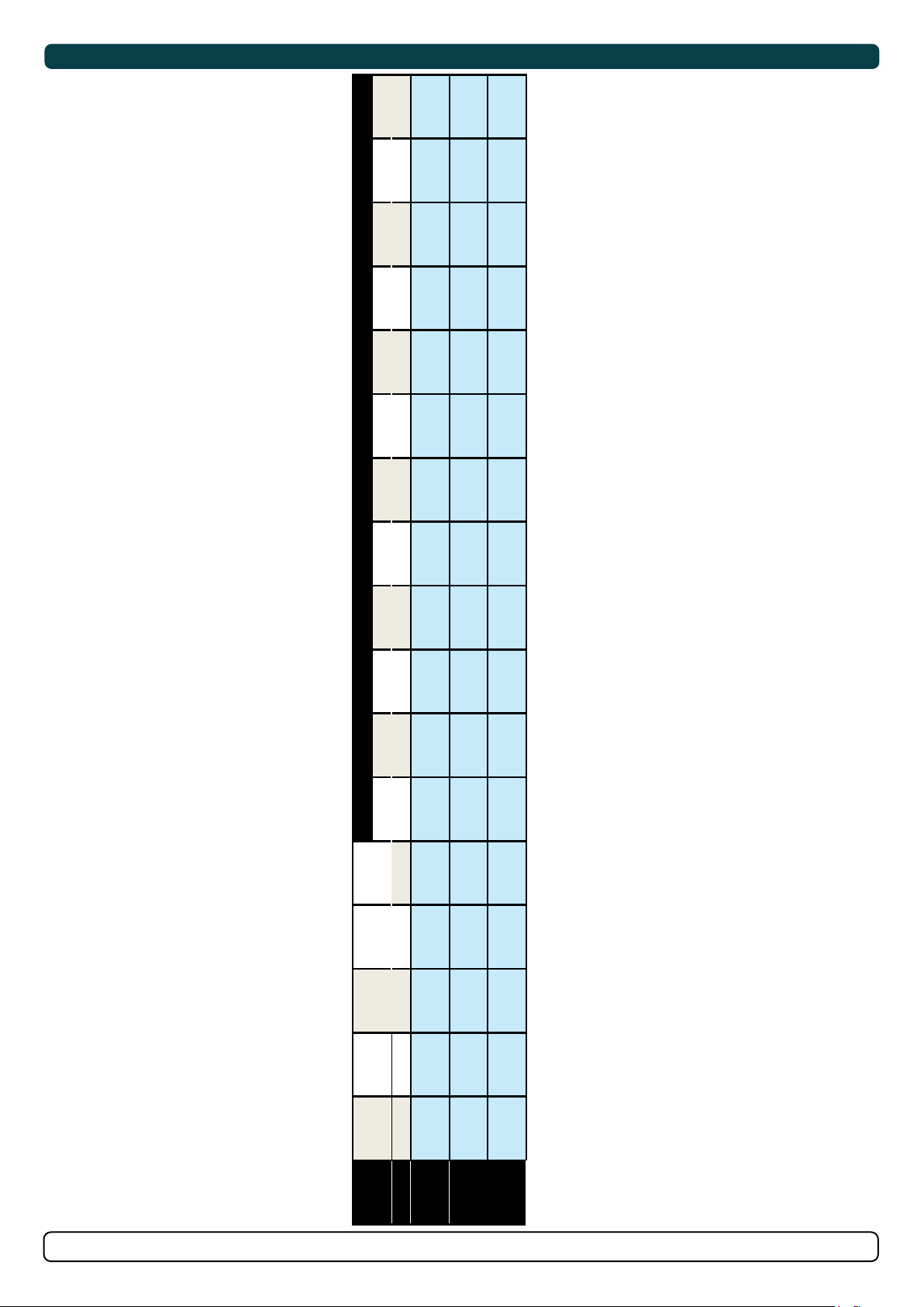
Electrical Specifi cations
MC_0077
<7m total + & - 7-14m total + & - 15-21m total + & - 22-28m total + & - 28-35m total + & - 36-45m total + & -
Min. Rec. Min. Rec. Min. Rec. Min. Rec. Min. Rec. Min. Rec.
mm2 35 50 50 70 70 95 95 120 120 2 x 70 2 x 70 2 x 95
AWG 2 1/0 1/0 2/0 2/0 3/0 3/0 4/0 4/0 2 x 2/0 2 x 2/0 2 x 3/0
AWG 3 2 1/0 1/0 2/0 2/0 3/0 3/0 4/0 4/0 2 x 2/0 2 x 2/0
Rec. fuse
CCA
Min. battery
draw
current
Nominal
Voltage
System
Model Size
ANL 150
EN: 330
DIN: 200
SAE: 380
*35/140 12 V 245 A
HydroPOD 35 & 50
mm2 50 50 70 95 120 2 x 70 2 x 70 2 x 95 2 x 95 2 x 120 2 x 120 2 x 120
AWG 1/0 1/0 2/0 3/0 4/0 2 x 2/0 2 x 2/0 2 x 3/0 2 x 3/0 2 x 4/0 2 x 4/0 2 x 4/0
ANL 325
EN: 600
DIN: 350
SAE: 665
12 V 370 A
mm2 25 25 25 35 35 50 35 50 50 70 70 70
ANL 150
DIN: 175
SAE :332
24 V 170 A
*50/1400
AWG 3 3 3 2 2 1/0 2 1/0 1/0 2/0 2/0 2/0
EN: 280
6398
-
11 2 0 21
17
Page 18
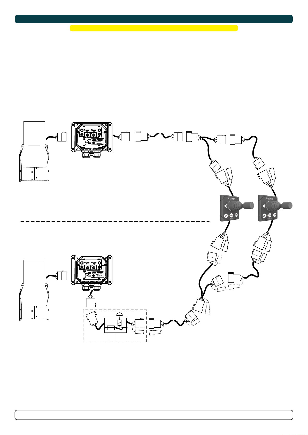
Control Panel Cable Installation
! Please refer to the graphic for special considerations relating to your model !
• All Sleipner control panels can be used in any combination.
• All control panels can be installed using:
• Y-connectors - for standard on/off
• T-connectors - for S-Link proportional power system.
(NB: If two or more control panels are operated at the same time in opposite directions, the electronic control box will stop the thruster until
it receives a single signal or thrust in one direction.)
• Sleipner on/off equipment it is entirely “plug & play” and require no additional con guration setup.
See the Control panel manual for more information.
Thruster
Motor
Ext. cable
4- or 5-lead
Y cable
4- or 5-lead
Ext. cable
4- or 5-lead
MC_0041
Manual Main switch
Automatic Main switch
Thruster
Motor
* 4 OR 5 LEAD EXTENSION
CABLES
* 5 LEAD EXTENSION
CABLES
Y cable
5-lead
Ext. cable
5-lead
18
Option: Automatic main switch. connects the battery to
the thruster. Operated from the control panel(s).
Requires 5-lead control cables.
HydroPOD 35 & 50
Ext. cable
5-lead
6398
-
11 2 0 21
MG_0115
Page 19

Control Panel Installation
For Control Panel installation please refer to the supplied manual in your Sleipner product delivery
Installation Guide
Control Panel
MC_0398
SLEIPNER AS
P.O. Box 519
N-1612 Fredrikstad
Norway
www.sleipnergroup.com
DOCUMENT ID:
REVISION:
DATE:
LANGUAGE:
HydroPOD 35 & 50
6398
-
11 2 0 21
19
Page 20

Pre-delivery Checklist
MC_0081
�.......... Propeller is fastened correctly to the shaft.
�.......... Propeller turns freely in tunnel.
�.......... Primer and anti-fouling have been applied to the gear house and propeller but NOT on the
anode or the gear house lid where the propeller is fastened.
�.......... Correct drive direction as per control panel.
�.......... The bolts holding the thruster are tightened correctly.
�.......... The bolts holding the motor to its bracket are tightened correctly.
�.......... All electrical connections are clean, dry and tight, and the correct cable, fuse and main
switch size.
�.......... No water leakage around hull penetrated studs
�.......... Check that there is no electrical connection between the electro motor body and positive
terminal on the motor, and between the electro motor body and the negative (A1) terminal
on the motor with an ohm meter.
The thruster has been installed as per the instructions in this manual and all points in checklist above have been controlled.
Signed: .........................................................................................
Date: .............................................................................................
Extra pre-delivery tests by installer / yard who does not use other quality control systems !
Thruster type: ................................................................................................................................................................................................
Serial number:...............................................................................................................................................................................................
Date of delivery:.............................................................................................................................................................................................
Correct drive direction as per control panel: ..................................................................................................................................................
The compartment for the thruster has been isolated from general bilge water and has no obvious or suspected risks for flooding:
......................................................................................................................................................................................................................
......................................................................................................................................................................................................................
......................................................................................................................................................................................................................
Other comments by installer: ........................................................................................................................................................................
.......................................................................................................................................................................................................................
.......................................................................................................................................................................................................................
......................................................................................................................................................................................................................
-
20
HydroPOD 35 & 50
6398
11 2 0 21
Page 21

Service and Support
Find your local professional dealer from our certifi ed
worldwide network for expert service and support.
visit our website www.sleipnergroup.com/support
MC_0024
Product Spare Parts and Additional Resources
MC_0024
For additional supporting documentation, we advise you
to visit our website www.sleipnergroup.com and fi nd your
Sleipner product.
Warranty statement
1. Sleipner Motor AS (The “Warrantor”) warrants that the equipment (parts, materials and embedded software of products) manufactured by the
Warrantor is free from defects in workmanship and materials for the purpose for which the equipment is intended and under normal use and
service (the “Warranty”).
2. This Warranty is in effect for two years (Leisure Use) or one year (Commercial and other Non-leisure Use) from the date of purchase by the end
user (for demonstration vessels, the dealer is deemed as end user).
3. This Warranty is transferable and covers the equipment for the specied warranty period.
4. The warranty does not apply to defects or damages caused by faulty installation or hook-up, abuse or misuse of the equipment including exposure
to excessive heat, salt or fresh water spray, or water immersion except for equipment specically designed as waterproof.
5. In case the equipment seems to be defective, the warranty holder (the “Claimant”) must do the following to make a claim:
(a) Contact the dealer or service centre where the equipment was purchased and make the claim. Alternatively, the Claimant can make the
claim to a dealer or service centre found at www.sleipnergroup.com. The Claimant must present a detailed written statement of the nature
and circumstances of the defect, to the best of the Claimant’s knowledge, including product identi cation and serial nbr., the date and place of
purchase and the name and address of the installer. Proof of purchase date should be included with the claim, to verify that the warranty period
has not expired;
(b) Make the equipment available for troubleshooting and repair, with direct and workable access, including dismantling of furnishings or similar,
if any, either at the premises of the Warrantor or an authorised service representative approved by the Warrantor. Equipment can only be returned
to the Warrantor or an authorised service representative for repair following a pre-approval by the Warrantor’s Help Desk and if so, with the Return
Authorisation Number visible postage/shipping prepaid and at the expense of the Claimant.
6. Examination and handling of the warranty claim:
(a) If upon the Warrantor’s or authorised service Representative’s examination, the defect is determined to result from defective material or
workmanship in the warranty period, the equipment will be repaired or replaced at the Warrantor’s option without charge, and returned to the
Purchaser at the Warrantor’s expense. If, on the other hand, the claim is determined to result from circumstances such as described in section 4
above or a result of wear and tear exceeding that for which the equipment is intended (e.g. commercial use of equipment intended for leisure use),
the costs for the troubleshooting and repair shall be borne by the Claimant;
(b) No refund of the purchase price will be granted to the Claimant, unless the Warrantor is unable to remedy the defect after having a reasonable
number of opportunities to do so. In the event that attempts to remedy the defect have failed, the Claimant may claim a refund of the purchase
price, provided that the Claimant submits a statement in writing from a professional boating equipment supplier that the installation instructions of
the Installation and Operation Manual have been complied with and that the defect remains.
7. Warranty service shall be performed only by the Warrantor, or an authorised service representative, and any attempt to remedy the defect by
anyone else shall render this warranty void.
8. No other warranty is given beyond those described above, implied or otherwise, including any implied warranty of merchantability, tness for a
particular purpose other than the purpose for which the equipment is intended, and any other obligations on the part of the Warrantor or its
employees and representatives.
9. There shall be no responsibility or liability whatsoever on the part of the Warrantor or its employees and representatives based on this Warranty
for injury to any person or persons, or damage to property, loss of income or prot, or any other incidental, consequential or resulting damage
or cost claimed to have been incurred through the use or sale of the equipment, including any possible failure or malfunction of the equipment or
damages arising from collision with other vessels or objects.
10. This warranty gives you specic legal rights, and you may also have other rights which vary from country to country.
MC_0024
Patents
At Sleipner we continually reinvest to develop and offer the latest technology in marine advancements. To see the many unique designs we have
patented visit our website www.sleipnergroup.com/patents
-
HydroPOD 35 & 50
6398
11 2 0 21
MC_0024
21
Page 22

MC_0037
..................................................................................................................................................................................................................................................
..................................................................................................................................................................................................................................................
..................................................................................................................................................................................................................................................
..................................................................................................................................................................................................................................................
..................................................................................................................................................................................................................................................
..................................................................................................................................................................................................................................................
..................................................................................................................................................................................................................................................
..................................................................................................................................................................................................................................................
..................................................................................................................................................................................................................................................
..................................................................................................................................................................................................................................................
..................................................................................................................................................................................................................................................
..................................................................................................................................................................................................................................................
..................................................................................................................................................................................................................................................
..................................................................................................................................................................................................................................................
..................................................................................................................................................................................................................................................
..................................................................................................................................................................................................................................................
..................................................................................................................................................................................................................................................
..................................................................................................................................................................................................................................................
..................................................................................................................................................................................................................................................
..................................................................................................................................................................................................................................................
..................................................................................................................................................................................................................................................
..................................................................................................................................................................................................................................................
..................................................................................................................................................................................................................................................
..................................................................................................................................................................................................................................................
..................................................................................................................................................................................................................................................
..................................................................................................................................................................................................................................................
..................................................................................................................................................................................................................................................
..................................................................................................................................................................................................................................................
..................................................................................................................................................................................................................................................
..................................................................................................................................................................................................................................................
..................................................................................................................................................................................................................................................
..................................................................................................................................................................................................................................................
MC_0037
Notes
Notes
..................................................................................................................................................................................................................................................
..................................................................................................................................................................................................................................................
..................................................................................................................................................................................................................................................
..................................................................................................................................................................................................................................................
..................................................................................................................................................................................................................................................
..................................................................................................................................................................................................................................................
..................................................................................................................................................................................................................................................
..................................................................................................................................................................................................................................................
..................................................................................................................................................................................................................................................
..................................................................................................................................................................................................................................................
..................................................................................................................................................................................................................................................
..................................................................................................................................................................................................................................................
..................................................................................................................................................................................................................................................
..................................................................................................................................................................................................................................................
..................................................................................................................................................................................................................................................
..................................................................................................................................................................................................................................................
..................................................................................................................................................................................................................................................
..................................................................................................................................................................................................................................................
..................................................................................................................................................................................................................................................
..................................................................................................................................................................................................................................................
..................................................................................................................................................................................................................................................
..................................................................................................................................................................................................................................................
..................................................................................................................................................................................................................................................
..................................................................................................................................................................................................................................................
..................................................................................................................................................................................................................................................
..................................................................................................................................................................................................................................................
..................................................................................................................................................................................................................................................
..................................................................................................................................................................................................................................................
..................................................................................................................................................................................................................................................
..................................................................................................................................................................................................................................................
..................................................................................................................................................................................................................................................
..................................................................................................................................................................................................................................................
-
22
HydroPOD 35 & 50
6398
11 2 0 21
Page 23

Notes
..................................................................................................................................................................................................................................................
..................................................................................................................................................................................................................................................
..................................................................................................................................................................................................................................................
..................................................................................................................................................................................................................................................
..................................................................................................................................................................................................................................................
..................................................................................................................................................................................................................................................
..................................................................................................................................................................................................................................................
..................................................................................................................................................................................................................................................
..................................................................................................................................................................................................................................................
..................................................................................................................................................................................................................................................
..................................................................................................................................................................................................................................................
..................................................................................................................................................................................................................................................
MC_0037
..................................................................................................................................................................................................................................................
..................................................................................................................................................................................................................................................
..................................................................................................................................................................................................................................................
..................................................................................................................................................................................................................................................
..................................................................................................................................................................................................................................................
..................................................................................................................................................................................................................................................
..................................................................................................................................................................................................................................................
..................................................................................................................................................................................................................................................
..................................................................................................................................................................................................................................................
..................................................................................................................................................................................................................................................
..................................................................................................................................................................................................................................................
..................................................................................................................................................................................................................................................
..................................................................................................................................................................................................................................................
..................................................................................................................................................................................................................................................
..................................................................................................................................................................................................................................................
..................................................................................................................................................................................................................................................
..................................................................................................................................................................................................................................................
..................................................................................................................................................................................................................................................
..................................................................................................................................................................................................................................................
..................................................................................................................................................................................................................................................
-
HydroPOD 35 & 50
6398
11 2 0 21
23
Page 24

© Copyright Sleipner Motor AS, 2021
The information given in the document
was correct at the time it was published.
However, Sleipner Motor AS can not
accept liability for any inaccuracies or
omissions it may contain. Continuous
product improvement may change the
product speci cations without notice.
Therefore, Sleipner Motor AS can not
accept liability for any possible
differences between product and
document.
Register your product and learn more
at www.sleipnergroup.com
SLEIPNER AS
P.O. Box 519
N-1612 Fredrikstad
Norway
www.sleipnergroup.com
MC_0030
Made in Norway
 Loading...