

SleepSafe Beds SleepSafer Hi Lo Assembly Instructions Manual
SleepSafer Hi Lo (High Bed)
Assembly Instructions
3135 Dillons Mill Road • Callaway, VA 24067
Toll Free • 866.852.2337 Fax • 540.334.2100
www.sleepsafebed.com
Thank you for purchasing the SleepSafer Hi Lo Safety Bed. With proper care, your bed will
provide years of safe use. We strongly recommend that this bed be assembled using two
people. Everything necessary to assemble your bed is included in a special box marked
“Additional Parts Inside” which is located in the box containing the headboard and footboard.
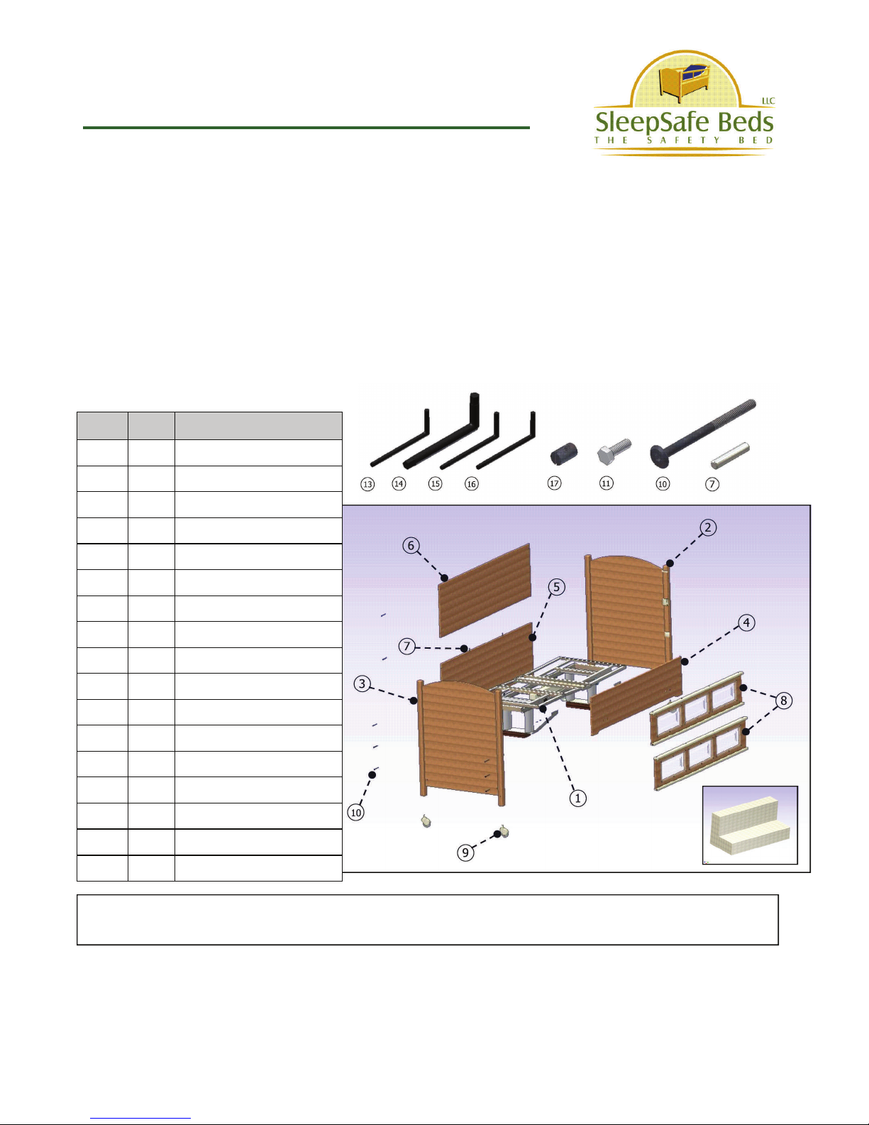
Carefully unpack the contents of your bed and verify that all parts are included using the diagram and chart below. Be sure to save two of the foam shipping blocks used to
package the electric frame. They will be needed to aid in assembly of your bed.
Parts List
Item Qty Description
1 1 Electric Frame Assembly
2 1 Headboard Assembly
3 1 Footboard Assembly
4 1 Front Panel
5 1 Back Bottom Panel
6 1 Back Top Panel
7 2 Alignment Pins
8 2 Safety Rails
9 4 Casters
10 16 90mm Allen Bolts
11 8 1” Hex Bolts
12 4 Foam Shipping Block
13 1 4mm Allen Wrench
14 1 1/4” Allen Wrench
15 1 #15 Torx Wrench
16 1 #10 Torx Wrench
17 16 Extra Barrel Nuts
Note: For clarity, all diagrams shown in these instructions show decking removed from
electric frames.
12
PLEASE CHECK ALL BOXES FOR HARDWARE BEFORE DISCARDING
DO NOT DISCARD FOAM BLOCKS WHICH ARE REQUIRED FOR ASSEMBLY
WARRANTY AND USER INFORMATION CAN BE FOUND AT THE END OF THESE INSTRUCTIONS
SleepSafer Hi Lo
Assembly Instructions Continued...
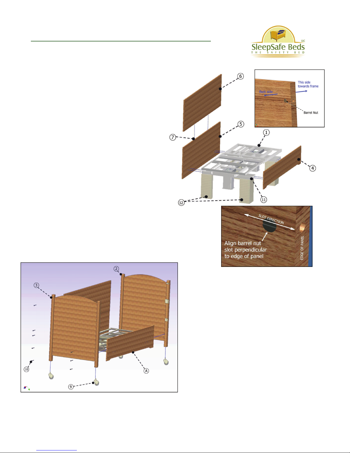
STEP 1
Set electric frame (#1) upright with foam
spacer blocks (#12) underneath each corner of the mounting brackets as shown.
Using the 8 silver hex bolts (#11), attach
front panel (#4) and back panel (#5) to
brackets on frame. Now, check the alignment of the decking on the electric frame
to each end of the panels. Even up the
spacing and tighten the 8 hex bolts. Unstrap the handset from the frame and set
it out of the way.
NOTE: In the diagram at right, the
head section will be to the right side
of the bed when you are facing the
safety rails. If you need to have the
head section of the bed to the left
side when facing the safety rails, reverse the panel installation from the
diagram.
STEP 2
Install 16 barrel nuts (#17) into holes at the
ends of all panels. Install headboard (#2) and
footboard (#3) to side panel/frame assembly
(A) using the 12 long allen bolts (#10) provided.
Do not tighten the bolts completely. Insert
two alignment pins (#7) into the holes in the
bottom back panel as illustrated in the diagram
above. Set the top back panel (#6) onto the
alignment pins, orienting the panel as shown in
the inset diagram. Insert 4 more of the long
allen bolts (#10) into the back panel. The
headboard and footboard will be elevated off
the floor when installed. Tighten all of the allen
bolts using the 4mm allen wrench (#13) provided in your hardware kit.
Install the 4 casters (#9) into the holes in the
bottom of the headboard and footboard legs.
You may now remove the foam spacers from
underneath the frame.
 Loading...