

SleepSafe Beds II Articulated, Plus Assembly Instructions Manual
SleepSafe II Articulated
(Medium Bed)
Assembly Instructions
3135 Dillons Mill Road • Callaway, VA 24067
Toll Free • 866.852.2337 Fax • 540.334.2100
www.sleepsafebed.com
Thank you for purchasing the SleepSafe Plus Safety Bed. With proper care, your bed will provide years of safe use. We strongly recommend that this bed be assembled using two people. Everything necessary to assemble your bed is included in a special box marked
“Additional Parts Inside” which is located in the box containing the headboard and footboard.
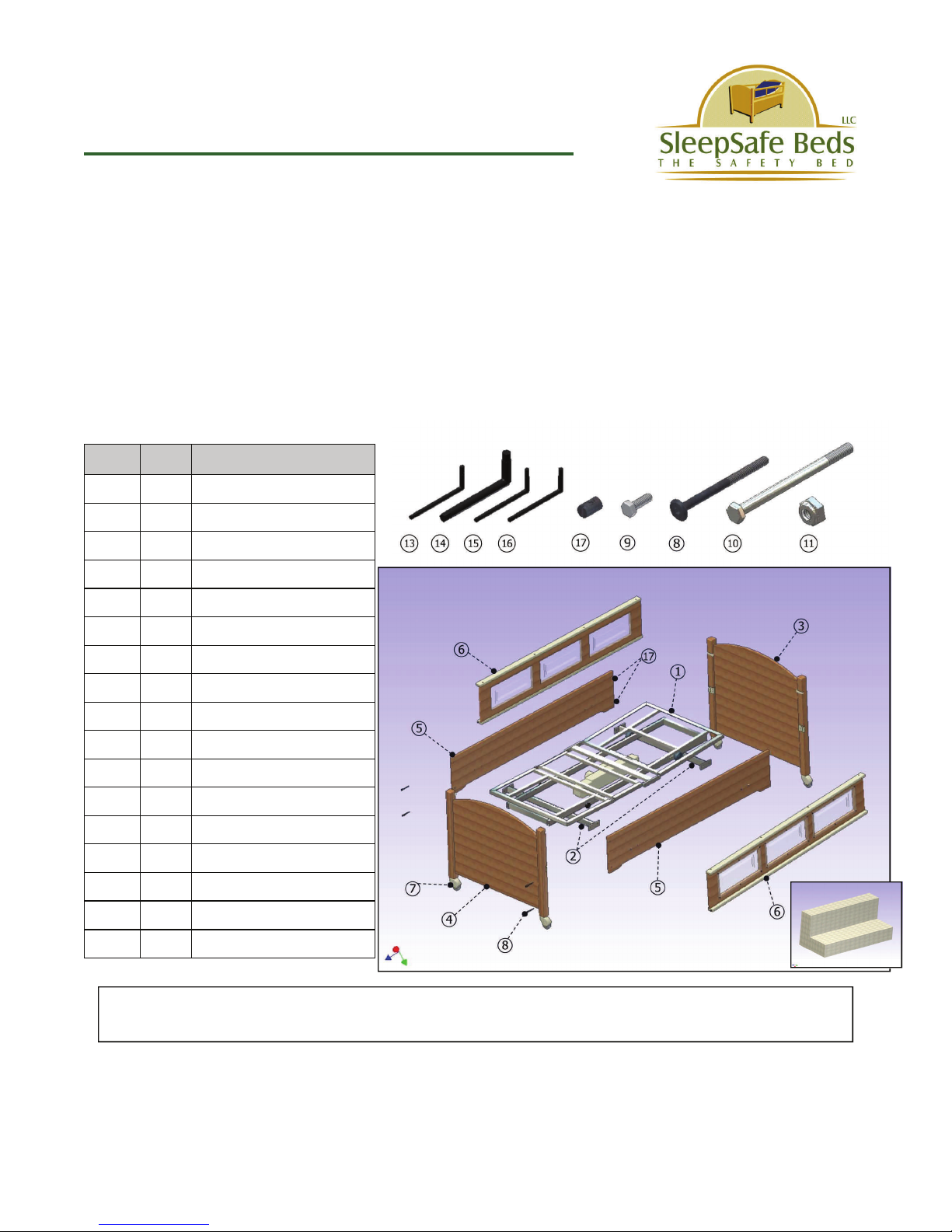
Carefully unpack the contents of your bed and verify that all parts are included using the diagram and chart below. Be sure to save the four foam shipping blocks used to pack-
age the electric frame. They will be needed to aid in assembly of your bed.
Parts List
Item Qty Description
1 1 Electric Frame Assembly
2 2 Mounting Bracket
3 1 Headboard Assembly
4 1 Footboard Assembly
5 2 Side Panels
6 2 Safety Rails
7 4 Casters
8 12 90mm Allen Bolts
9 8 1” Hex Bolts
10 4 4-1/2” Hex Bolts
11 4 5/16” Nylon Lock Nuts
12 4 Foam Shipping Block
13 1 4mm Allen Wrench
14 1 1/4” Allen Wrench
15 1 #15 Torx Wrench
16 1 #10 Torx Wrench
17 12 Barrel Nuts
Note: For clarity, all diagrams shown in these instructions show decking removed
from electric frames.
PLEASE CHECK ALL BOXES FOR HARDWARE BEFORE DISCARDING
DO NOT DISCARD FOAM BLOCKS WHICH ARE REQUIRED FOR ASSEMBLY
WARRANTY AND USER INFORMATION CAN BE FOUND AT THE END OF THESE INSTRUCTIONS
12
SleepSafe II Articulated
Assembly Instructions Continued...
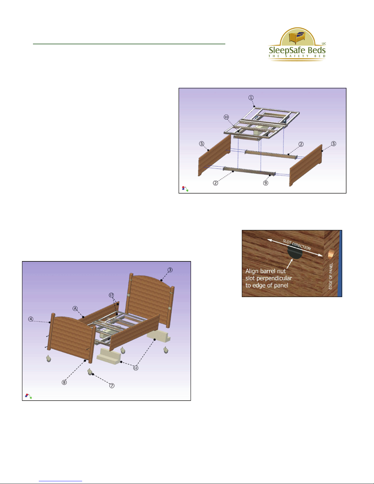
STEP 1
Determine which height setting is desired for
your bed. Two settings are available with
the lowest being 23-1/2” from the floor to
the top of the mattress and the highest being
27-1/2”. Attach the mounting brackets (#2)
using 8 1” Hex Bolts (#9) as shown at right
to the Side Panels (#5) Snug bolts but do
not tighten yet. Now, set the electric frame
(#1) onto the mounting brackets, aligning
the holes in the frame with the corresponding bracket holes. Insert 4 4-1/2” hex bolts
(#10) through holes and attach 5/16” lock
nut (#11). When all bolts are in, tighten all
securely. Even up the spacing between the electric frame decking and each end of the
wood panels. Now tighten the 1” hex bolts attaching the wood panels to the mounting
brackets. Unstrap the remote control from the frame and set it out of the way.
STEP 2
Set side panel/frame assembly onto the 4 foam
shipping blocks (#15) as shown at left. Insert
12 barrel nuts (#17) into holes on each end of
the side panels. Install headboard (#3) and
footboard (#4) to side panel/frame assembly
(A) using the 12 long allen bolts (#8) provided.
(The barrel nuts should face the interior of the
bed) The headboard and footboard will be elevated off the floor when installed. Tighten the
allen bolts using the 4mm allen wrench (#13)
provided in your hardware kit.
Install the 4 casters (#7) into the holes in the bottom of the headboard and footboard
legs.
You may now remove the foam spacers from underneath the frame.
 Loading...