

Page 1
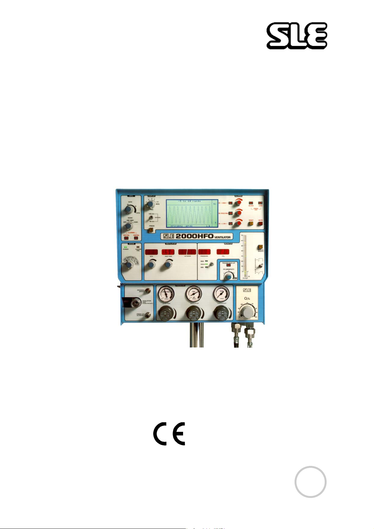
SLE 2000 HFO
Ventilator
User manual
High Frequency Oscillatory
Ventilator
0120
Issue
13
Page 2

Contact Information:
SLE Limited
Twin Bridges Business Park
232 Selsdon Road
South Croydon
Surrey CR2 6PL
Telephone: +44 (0)20 8681 1414
Fax: +44 (0)20 8649 8570
Web site: www.sle.co.uk
All rights reserved. No part of this publication may be reproduced, stored in any retrieval system, or
transmitted in any form or by any means, electronic, mechanical, photocopy, recording or otherwise,
without prior permission of SLE. © Copyright SLE 01/10/2004.
Manual : UM0008 Issue 13
SLE Part Nº: N2006/00
Page 2 of 70
Page 3

Contents
1. Introduction .................................................................................................8
1.1. Principles of Operation SLE 2000 HFO..............................................9
2. User/Owner Responsibility. .......................................................................11
3. Warnings ......................................................................................................12
3.1. Operational Warnings.........................................................................12
3.2. Clinical Warnings................................................................................13
4. Glossary of Abbreviations Used in This Manual ......................................15
5. Symbols .......................................................................................................16
Operating Instructions
6. SLE 2000 HFO Functional Tests ................................................................18
6.1. Pressure Regulators and Gauges ...................................................... 18
6.2. Automatic Power On Test...................................................................19
6.3. Setting Alarm Limits............................................................................ 19
6.4. CPAP Mode........................................................................................19
6.5. CMV Mode..........................................................................................20
6.6. PTV Mode...........................................................................................20
6.7. SIMV Mode.........................................................................................21
6.8. HFO Modes ........................................................................................ 21
6.9. Alarm Test ..........................................................................................23
6.9.1. To Verify Alarms...........................................................................23
6.9.2. High Alarm ...................................................................................23
6.9.3. Cycle Fail Alarm...........................................................................23
6.9.4. Low Alarm....................................................................................23
6.9.5. Leak/block Alarm..........................................................................24
6.9.6. Mains Failure Alarm.....................................................................24
6.9.7. O2 Blender Alarm......................................................................... 24
6.9.8. Oxygen Concentration Alarm.......................................................24
6.10. O2 Cell..............................................................................................24
6.10.1. Condition Of O2 Cell..................................................................24
7. Basic Set Up for the SLE 2000 HFO .......................................................... 25
7.1. To Use the SLE 2000 HFO in CPAP Mode........................................ 27
7.2. To Use the SLE 2000 HFO in CMV Mode..........................................28
7.3. Patient Trigger Modes ........................................................................ 29
7.3.1. To Use SLE 2000 In PTV or SIMV Mode...................................29
7.4. To Use the SLE 2000 HFO in the Oscillator Mode.............................30
Technical information
8. Ventilator Controls ...................................................................................... 34
8.1. Electronic Module............................................................................... 34
8.1.1. Mode Switch (5 positions).......................................................... 34
8.1.2. System Fail LED ..........................................................................34
8.1.3. CPAP Mode .................................................................................34
Page 3 of 70
Page 4

8.1.4. CMV Mode...................................................................................34
8.1.5. PTV Mode....................................................................................35
8.1.6. SIMV Mode. .................................................................................35
8.1.7. BPM .............................................................................................37
8.1.8. Inspiration Time............................................................................37
8.1.9. I:E Ratio .......................................................................................37
8.1.10. Oxygen (FlO2)............................................................................ 37
8.1.11. Pressure Display........................................................................37
8.1.12. Three Position Switch. ............................................................... 37
8.1.13. Pressure Display Bargraph........................................................38
8.1.14. Pressure Wave Switch...............................................................38
8.1.15. Manual Breath............................................................................38
8.1.16. HFO Controls............................................................................. 39
8.1.17. Time Control Switch................................................................... 39
8.1.18. Screen Switch............................................................................39
8.1.19. Freeze........................................................................................ 39
8.2. Pneumatic Module..............................................................................40
8.2.1. Proximal Airway ........................................................................... 40
8.2.2. Removable Exhalation Block ....................................................... 40
8.2.3. Fresh Gas Port.............................................................................40
8.2.4. Regulator and Pressure Gauges..................................................41
8.2.5. O2 Blender (% FlO2)....................................................................41
9. Alarms ..........................................................................................................42
9.0.1. Microprocessor.............................................................................42
9.0.2. Mains Failure Audible Alarm........................................................ 42
9.0.3. Gas Supply Failure Alarm............................................................42
9.0.4. Fresh Gas Fail Alarm (Block & Leak)...........................................43
9.0.5. HFO Fail.......................................................................................43
9.0.6. Fan Fail........................................................................................43
9.0.7. Adjustable Alarm.......................................................................... 43
9.0.8. High Alarm ...................................................................................43
9.0.9. Cycle Fail Alarm...........................................................................44
9.0.10. Low Alarm..................................................................................44
9.0.11. Delta P Alarm.............................................................................44
9.0.12. O2 BLender Alarm ..................................................................... 44
9.0.13. Oxygen Alarm ............................................................................44
9.0.14. Alarm Mute.................................................................................44
9.0.15. Alarm Volume.............................................................................44
9.0.16. Alarm Verification.......................................................................44
10. Auxiliary Output ........................................................................................45
11. Rear Panel .................................................................................................. 46
12. Patient Circuit Connection ....................................................................... 47
13. Filter Systems ............................................................................................ 49
13.1. Bacterial filter, SLE Part Nº:N2029 (Autoclavable)........................... 49
13.2. Bacterial filter, SLE Part Nº:N2587 (Single use)............................... 49
13.2.1. Precautions when using bacterial filter N2587...........................49
Page 4 of 70
Page 5

14. Cleaning, Disinfection and Sterilization ..................................................50
14.1. Preparation of a new ventilator.........................................................50
14.2. Cleaning and disinfection of an in-service ventilator......................... 50
14.2.1. Cleaning, Disinfection & Sterilization chart ................................ 51
14.3. Cleaning method...............................................................................51
14.4. Disinfection method.......................................................................... 52
14.5. Sterilization method.......................................................................... 52
15. Service and Maintenance Programmes .................................................. 53
15.1. Maintenance.....................................................................................53
15.2. Overhaul at 10,000 and 20,000 hours.............................................. 53
16. User Operational Checks .........................................................................54
17. SLE 2000 HFO Trouble Shooting Chart ..................................................55
18. Service Programmes ................................................................................ 58
19. Pressure Unit Conversion Constants .....................................................60
20. Technical Specification ............................................................................61
20.1. Conventional Ventilation...................................................................61
20.2. HFO Ventilation ................................................................................ 61
20.3. Displays............................................................................................ 61
20.4. Controls ............................................................................................ 62
20.5. Alarms...............................................................................................63
20.6. Air and Oxygen Supplies.................................................................. 63
20.6.1. Oxygen supply ...........................................................................63
20.6.2. Air supply ...................................................................................63
20.7. Power , Dimensions etc....................................................................64
20.8. Environmental Storage Conditions................................................... 64
21. Consumables and Accessories for SLE 2000 HFO ................................ 65
22. Ordering Information for the SLE2000 HFO ........................................... 67
22.0.1. Options....................................................................................... 67
22.0.2. Air Compressors ........................................................................67
23. Technical Bulletins ................................................................................... 68
Page 5 of 70
Page 6

This page is intentionally blank.
Page 6 of 70
Page 7

How to use the SLE2000 HFO
NOTE THE WARNINGS (PAGE 12) MUST BE READ AND UNDERSTOOD
BEFORE USING THE SLE2000 HFO VENTILATOR. FAILURE TO DO SO COULD
LEAD TO INJURY OR DEATH
1 PERFORM THE FUNCTIONAL TESTS : PAGE 18
(THIS SHOULD TAKE NO MORE THAN 20 MINUTES)
2 SETUP THE SLE2000 HFO IN THE CHOSEN MODE: PAGE 25
3 THE SLE2000 HFO IS READY FOR USE
FOR MORE INFORMATION SEE TECHNICAL SECTION PAGE 34
FOR TROUBLE SHOOTING SEE TROUBLESHOOTING CHART PAGE 55
Page 7 of 70
Page 8

1. Introduction
The SLE2000 HFO ventilator is designed for use on neonates/infants. Its principle of
operation is time cycled, pressure limited ventilation using a constant fresh gas flow.
Main features are that it has no expiratory valve but uses a reverse flow of mixed gas
that is injected into the expiratory limb of the patient circuit from the exhaust manifold.
This flow of gas has the effect of compressing 5 LPM humidified gas into the patient
ET tube.
The advantage of this system is that there is no expiratory resistance due to valves or
diaphragms, therefore no inadvertent PEEP is generated. Also the fresh gas flow
does not require adjusting for various rates. Another advantage is that the driving flow
in the exhaust manifold is controlled by a regulator and therefore provides constant
pressure at all breathing rates.
The oscillatory feature is provided by a rotating jet, driven by a motor, situated at the
rear of the exhaust block. From this jet a stream of driving gas is rotated into the
exhalation manifold which provides both, an active inspiratory and active expiratory
flow. It can also be combined with a conventional mode such that we can have
oscillation superimposed on the inspiratory pressure plateau, or during the expiration
phase, or a combination of both. Finally with the ventilator operating in the CPAP
mode, the SLE2000 HFO can act as a pure oscillator where the mean airway pressure
is adjusted via the CPAP control, and the differential pressure can be set by the
oscillation regulator.
Another main feature of the ventilator is its patient trigger system. This functions
without any transducer in the patient circuit, on the principle of monitoring the rate of
change of pressure during the onset of inspiratory effort. In fact it measures
inspiratory flow by this means and not a pressure plateau.
Additionally the SLE2000 HFO has a built in oxygen monitoring cell, fresh gas and
leak alarms.
Page 8 of 70
Page 9
1.1 Principles of Operation SLE 2000 HFO
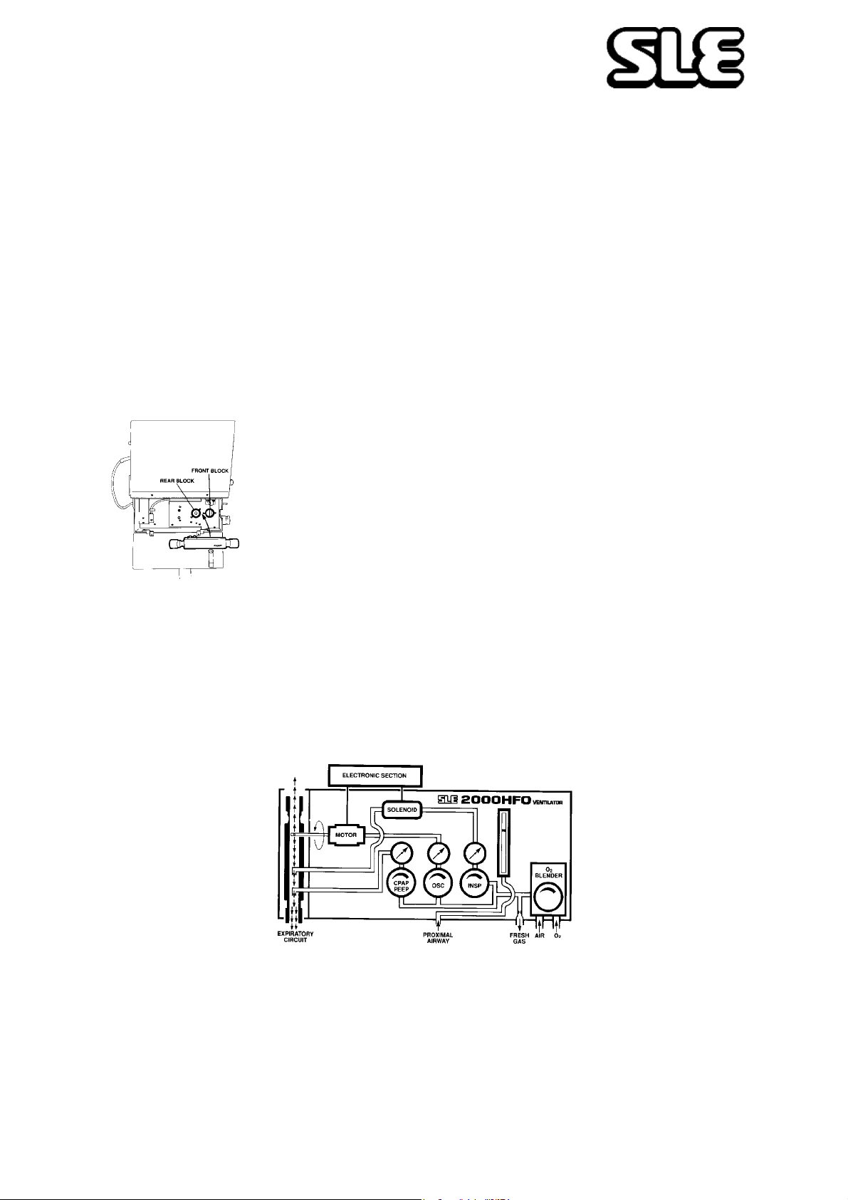
The patient circuit is supplied with a constant fixed flow of fresh gas at 5 litres per
minute. This gas comes from the internally mounted Oxygen Blender and its
concentration is monitored by a fuel cell and displayed on the FlO2 digital display.
This Fresh Gas Supply is then passed through a humidifier to the Inspiratory port of
the patient ET connector . Built into the ventilator are circuits to detect either a gas flow
failure or a tubing blockage. This circuitry requires a restrictor fitted into the Inspiratory
port of the patient circuit. Therefore, only SLE2000 approved patient circuit must be
used with this equipment.
The Exhalation block mounts onto two pressure manifold blocks as shown.
The front block has two nozzles. The first is used to generate CPAP/PEEP via the
CPAP/PEEP regulator, by generating an opposing flow to the fresh gas in the
exhalation tube thus creating CPAP/PEEP. The second is used to generate the peak
Inspiratory pressure. The Inspiratory regulator sets the pressure that is supplied to a
solenoid valve which is connected to the rear nozzle.
The Electronic Section controls the rate and duration of opening of the solenoid valve.
When the valve is open the Driving Gas enters the expiratory tube in opposition to the
Fresh Gas flow. This opposing flow acts as a pneumatic piston and creates a
pressure plateau at the ET connector
The lung inflation pressure and hence the tidal volume are controlled by the
Inspiratory regulator in conventional ventilation.
Page 9 of 70
Page 10

The same gas mixture from the Oxygen Blender is used to supply the patient Fresh
Gas, CPAP, Inspiratory and Oscillation driving gas pressure. This avoids any
possibility of dilution of the Fresh
Gas mixture.
There is a wave shape switch. This modifies the Driving Gas flow rate from the
Solenoid valve through the nozzle and is used to slow down the rise time of the
pressure waveform. In the taper position The rise time is approximately 250 ms.
The second or rear manifold block is the High Frequency Oscillator pressure
generator. Creating a pressure by means of a spinning jet of gas thus providing an
active positive and negative waveform (Sinusoidal). Pressure is controlled via the
oscillator regulator and frequency via the Frequency or
Rate control.
When operating the HFO in Inspiratory or expiratory mode, gas release is controlled
via a solenoid synchronised with the Inspiratory time and BPM.
Page 10 of 70
Page 11

2. User/Owner Responsibility.
This SLE 2000 HFO INFANT VENTILATOR and the authorised accessories for it
are designed to be used in accordance with supplied manuals and instructions.
This equipment must be periodically checked, recalibrated, maintained and
components repaired and replaced when necessary for the equipment to operate
safely and reliably.
Parts that have failed, in whole or in part, or exhibit excessive wear, or are
contaminated, or are otherwise at the end of their useful life, should not be used
and must be replaced immediately with parts supplied by SLE, or parts which are
otherwise approved by SLE. Equipment which is not functioning correctly or is
otherwise in need of repair or maintenance must not be used until all necessary
repairs and/or maintenance have been completed and a factory authorised service
representative has certified that the equipment is fit and ready for use. This
equipment, its accessories or component parts should not be modified. The use of
non-approved parts or accessories will invalidate the warranty.
The owner/user of this equipment shall have the sole responsibility and liability for
any damage or injury to persons or property (including the equipment itself)
resulting from operation not in accordance with the operating instructions, or from
faulty maintenance not in accordance with the authorised maintenance instructions,
or from repair by anyone other than the factory authorised service representative,
or from unauthorised modification of the equipment or accessories, or from the use
of components or accessories that have been either damaged or not authorised for
use with this equipment by the manufacturer.
Page 11 of 70
Page 12

3. Warnings
3.1 Operational Warnings
The following warnings must be read and understood before using the SLE2000 HFO
ventilator. Failure to do so could lead to injury or death.
1 The whole of this manual should be read and understood before using the
SLE2000 HFO Operators must be suitably trained and clinically authorised for
using the SLE2000 HFO with patients. Particular care should be taken to check
the ventilator pressures prior to changing modes.
2 Oxygen - Clinical use. Oxygen is a drug and should be prescribed as such.
3 Oxygen - Fire Hazard. Oxygen vigorously supports combustion and its use
requires special precaution to avoid fire hazards. Keep all sources of ignition
away when oxygen is in use. Do Not use oil or grease on oxygen fittings or
where oxygen is used.
4 Audible and Visual warning alarms indicate a potentially harmful condition to the
patient. However when ventilating a patient with a 3mm or smaller size
endotracheal tubes, in case of patient extubation or the ET tube
disconnecting from its ET connector, only the monitoring of flow (module
SLE 2100), or of SpO2, or Pt02/PtCO2 will dependably alert the medical
team to an alarm situation, not the monitoring of pressures.
5 When the ventilator is being used on a patient, a suitably trained person must be
in attendance at all times to take prompt action should an alarm or other
indication of a problem occur.
6 The ventilator functional tests must be carried out each time the SLE 2000 HFO
is used on patients. If any of these tests do not function as described then there
is a problem and the ventilator must not be used until it is rectified.
7 The humidifier used in the patient circuit must be operated and maintained in
accordance with its manufacturer’s instructions.
8 Any water trap used in the patient circuit must be drained regularly before it is
full.
9 Failure to comply with the recommended service programs could lead to injury to
the patient, operator or damage to the ventilator . It is the owners responsibility to
ensure that the equipment is regularly maintained.
10 Functioning of this ventilator may be adversely affected by high frequency
surgical (Diathermy) defibrillators, short-wave therapy or equipment producing
strong magnetic fields, operating in the vicinity.
11 The Ventilator must be connected to a suitably rated and grounded electrical
power source.
12 There is no special protection provided against ingress of water or liquids.
13 The equipment is not suit able for use with, or in the presence of flammable
anaesthetic mixtures.
Page 12 of 70
Page 13

14 Use only SLE approved patient circuits. On no account should antistatic or
electrically conductive tubing be used in the patient circuit.
15 No external volt age should be applied to the auxiliary socket. Any connections to
this socket must be approved by SLE and screened to comply with EMC
regulations. Ensure protection cap is fitted when socket is not in use.
16 The electronic module of the ventilator contains a primary battery, if the
ventilator is not to be used for 3 months or more, then the battery should be
removed.
17 Care should be taken when attaching other equipment as this may affect
stability.
3.2 Clinical Warnings
Failure to take corrective action when the alarms are activated could result in injury or
death to the patient.
There are risks inherent in the use of both conventional and high-frequency forms of
mechanical ventilation in the newborn and during infancy and childhood. These may
include:
1 Under- or over-ventilation (with consequent abnormalities in blood gases);
2 Incorrect humidification;
3 Intracranial haemorrhage, cerebral ischaemia;
4 Chronic lung disease (bronchopulmonary dysplasia in the newborn);
5 Damage to trachea and bronchi;
6 Over- or under-inflation of the lung;
7 Atalectasis;
8 Air leak syndrome (pneumothorax, pneumomediastinum, pneumopericardium.
pulmonary interstitial emphysema);
9 circulatory abnormalities (reduced systemic or pulmonary venous return,
hypotension, tachycardia, bradycardia, reduced cardiac output, excessive
variability of blood pressure);
10 Mobilisation of secretions and airway blockage.
Page 13 of 70
Page 14

Maintenance of an adequate airway is paramount in the infant or child undergoing
high-frequency oscillatory ventilation. The following points should be stressed in
airway management on units employing HFOV:
1 The largest endotracheal tube should be used which is compatible with a close,
but not tight, fit in the larynx;
2 Chest wall "bounce" (vibrations of chest and abdominal wall caused by HFOV)
should be verified regularly as part of nursing care;
3 Transcutaneous carbon dioxide measurement or frequent arterial blood gas
samples must be employed to alert the users to partial or total airway failure;
4 Avoid episodes of total disconnection during endotracheal tube toilet.
The minimum patient monitoring requirements for HFOV are:
1 ECG/heart rate;
2 Chest wall movement;
3 Blood pressure (continuous intravascular/regular, intermittent measurements);
4 Oxygen saturation;
5 Transcutaneous carbon dioxide / intravascular carbon dioxide / regular,
intermittent arterial/ capillary samples;
6 Regular arterial blood gases;
7 Regular chest X-rays;
8 Regular cranial ultrasound examinations (in the newborn);
9 Standard nursing care for Intensive Care patients.
Special care should be taken when ventilating using HFOV during the administration
of natural surfactant to avoid "foaming" of surfactant in the lung and subsequent
deterioration.
When switching from conventional to high-frequency ventilation, or vice-verse, rapid
alterations in ventilator settings and inspired oxygen concentrations may be required.
Exposing a baby to elevated concentrations of oxygen may lead to Retrolental
Fibroplasia (retinopathy of prematurity).
HFOV should only be instituted by fully trained and experienced medical personnel.
Page 14 of 70
Page 15

4. Glossary of Abbreviations Used in This Manual
bar Unit of Barometric Pressure Kg Kilogram
BPM Breaths Per Minute LED Light Emitting
Diode
cm Centimetre LF Low Frequency
cms Centimetres of Water LPM Litres per Minute
cmH2O Centimetres of Water MIT Maximum
Inspiratory Time
CMV Controlled Mechanical Ventilation ml Millilitres
CPAP Continuous Positive Airway Pressure ms Millisecond
°C Degrees Celsius O
2
Oxygen
°F Degrees Fahrenheit PTV Patient Triggered
Ventilation
dP Delta Pressure PIP Peak Inspiratory
Pressure
EMC Electromagnetic Compatibility PEEP Positive End
Expiratory
Pressure
ET Endotracheal psi Pounds per
Square Inch
FIO
2
Fractional Concentration of Inspired
SaO
2
Saturated oxygen
Oxygen
Hz Hertz SIMV Synchronised
Intermittent
Mandatory
Ventilation
HFO High Frequency Oscillation tcPCO2Transcutaneous
Carbon Dioxide
HFOV High frequency oscillatory ventilation tcPO
Transcutaneous
2
Oxygen
I:E Inspiratory : Expiratory Ratio ≈ Approximately
equal to
Insp. Inspiration Time
Page 15 of 70
Page 16
5. Symbols
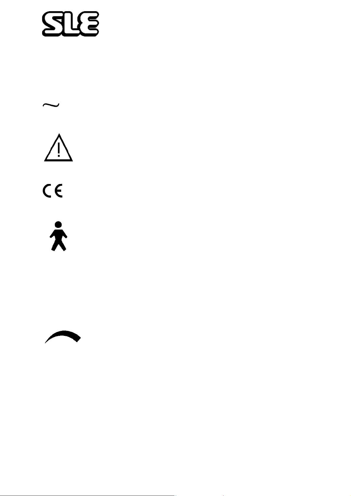
The Following Symbols are used on the Equipment
Alternating Current
Attention, consult accompanying documents.
Conformance mark and notified body registration
0120
Type B (IEC601-1) protection against electric shock.
I On (power: connection to the mains)
O Off (power: disconnected from the mains)
Rotate: clockwise to increase, anticlockwise to decrease
Page 16 of 70
Page 17
Operating Instructions
Page 17 of 70
Page 18
Operating Instructions
6. SLE 2000 HFO Functional Tests
The following functional tests must be carried out to ensure that this equipment
is working correctly before connection to a patient.
• NOTE: IF ANY OF THESE TESTS DO NOT FUNCTION AS DESCRIBED,
THERE IS A PROBLEM AND THE UNIT SHOULD NOT BE USED UNTIL IT
HAS BEEN REPAIRED. PLEASE CONTACT AN SLE APPROVED
ENGINEER, OR SLE.
With HFO and Mode switches set to OFF, High alarm set to maximum and all other
variable controls set to minimum.
Step 1. Connect AIR, OXYGEN Hoses to ventilator and plug into
gas supplies, at a gas pressure of about 4 bar. Connect
mains cable to a suitably rated and grounded electrical
power source.
Step 2. Connect SLE approved patient circuit with test lung to the ventilator.
• For further information see page 47 or instructions supplied with patient circuit.
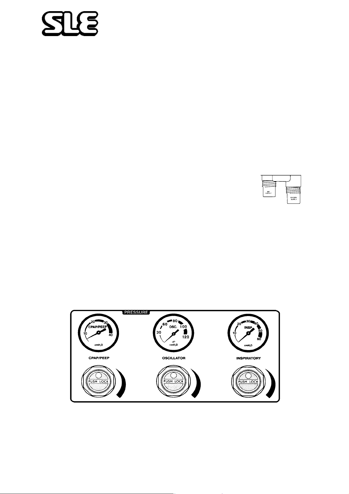
6.1 Pressure Regulators and Gauges
Check in turn the CPAP/PEEP, OSCILLATOR and INSPIRATORY regulators and
gauges by turning the regulator controls from minimum to maximum and making
sure that the gauges read between minimum and maximum. Return regulators to
minimum.
Regulator Controls are lockable. Push to lock, Pull to unlock.
Note: These gauges are for indication only and not for measuring operating
pressures.
Page 18 of 70
Page 19

Operating Instructions
6.2 Automatic Power On Test
Select ventilator mode to CPAP.
The ventilator will now carry out a self test as follows.
Power LED shows green and an automatic test of functions & alarms is initialised.
Firstly the displays and audible alarms are turned on for approximately two seconds
to demonstrate that they are operable, then for a further three seconds all the digital
displays show a sequence of numbers from O to 9 before returning to their normal
state.
Note: HFO Fail and Block LEDs do not come on during this sequence.
6.3 Setting Alarm Limits
• Set the High Alarm to maximum 60 cmH2O
• Set the Cycle Fail Alarm to approximately 28 cmH2O
• Set the Low Alarm to minimum -60 cmH2O
6.4 CPAP Mode
Set CPAP/PEEP Regulator to give 30 cmH2O on the
pressure display with the pressure display selector switch
in the MIN position.
Set Inspiratory Regulator to 20 cmH2O
Ensure that:-
•Bargraph display reads 30 cmH2O ± 2 cmH2O
• CPAP/PEEP gauge reads ≈30 cmH2O
• An Inspiratory cycle is initiated when manual breath button is pressed
Note: Alarm limits will also be shown on the bargraph display.
Page 19 of 70
Page 20
Operating Instructions
6.5 CMV Mode
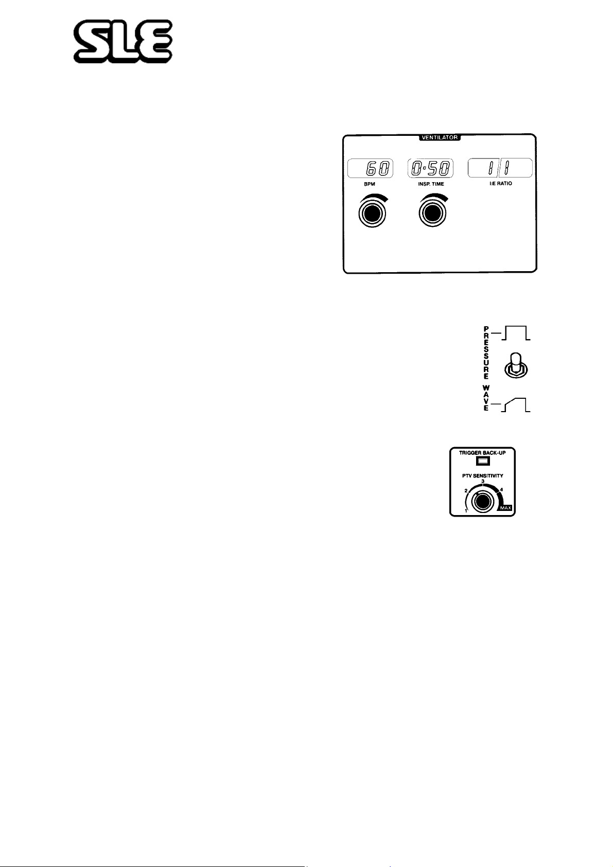
Step 1. Set the following ventilator conditions :-
• CPAP/PEEP regulator to 0 cmH2O
• Inspiratory regulator to ≈ 30 cmH2O
• Mode switch to CMV
•BPM Rate to 60
•INSP TIME to 0.50
• Cycle Fail Alarm to mid waveform
• Press Reset to cancel all alarms
Ensure that :-
• The ventilator is cycling
• I:E Ratio display reading 1:1
• Pressure waveform is shown on graphics display
• Pressure waveform shape changes with operation of PRESSURE
WAVE SWITCH. (Return the switch to the square wave setting.)
6.6 PTV Mode
Set BPM rate to 20
Set the CPAP/PEEP regulator to 10 cmH2O on the gauge
Set the PTV Sensitivity to 3
Select PTV with mode switch.
Ensure that :-
• Ventilator should continue to cycle
•BPM display reading is initially 0
• TRIGGER BACK-UP LED is “ON”
Apply slight pressure to test lung and release to simulate patient inspiratory effort.
Ensure that with each operation :-
• The ventilator cycles once.
• The TRIGGER BACK-UP LED is “OFF”.
Page 20 of 70
Page 21
Operating Instructions
6.7 SIMV Mode
Select SIMV with mode switch.
Ensure that:-
• The ventilator continues to cycle.
• The BPM display shows set rate.
• The TRIGGER BACK-UP LED illuminates on each inspiration.
Apply a varying pressure to test lung to simulate patient breathing.
Ensure that:-
• The ventilator continues to cycle at the set rate but synchronised with the
pressure from test lung.
• The TRIGGER BACK-UP LED is “OFF”.
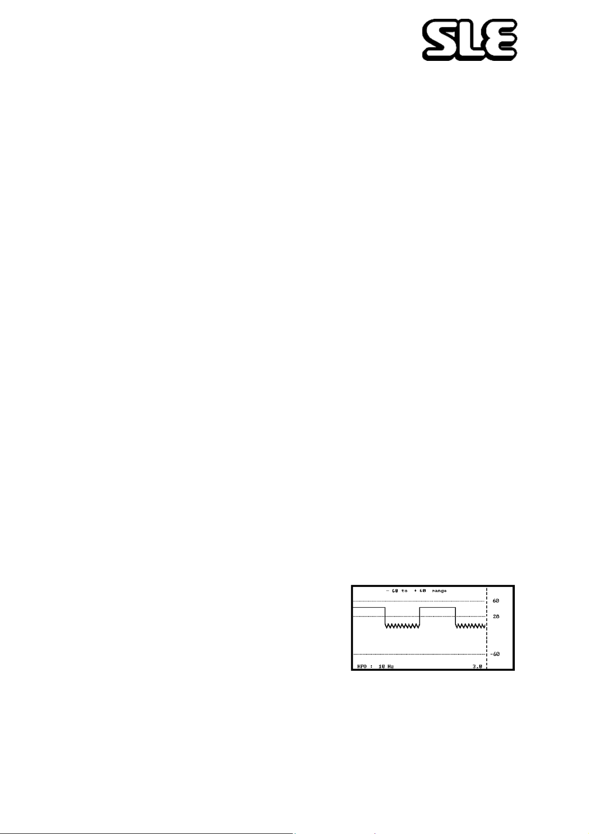
6.8 HFO Modes
Set the following conditions:-
•CMV Mode
•BPM rate to 30
•INSP Time to 1.00
• Oscillator Regulator to ≈ 30 cmH2O
• Inspiratory Regulator to ≈ 20 cmH2O
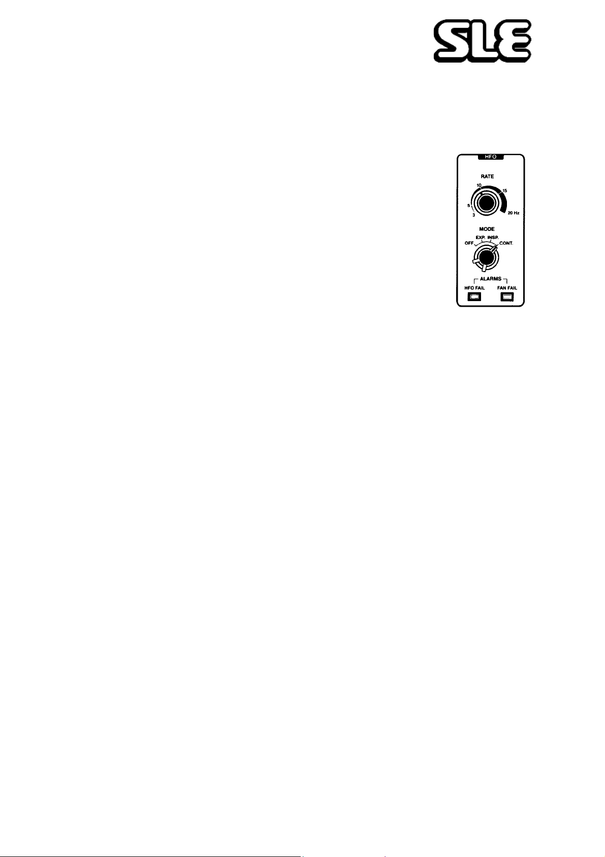
• HFO Mode to EXP
• HFO Rate to 10 Hz
• Display Switch to 3 seconds
• Screen Switch to ±60 cms
• Press Alarm Mute Button
Ensure that :-
• The ventilator is cycling.
• 10 Hz oscillation shown on expiratory cycle of
waveform.
Page 21 of 70
Page 22
Operating Instructions
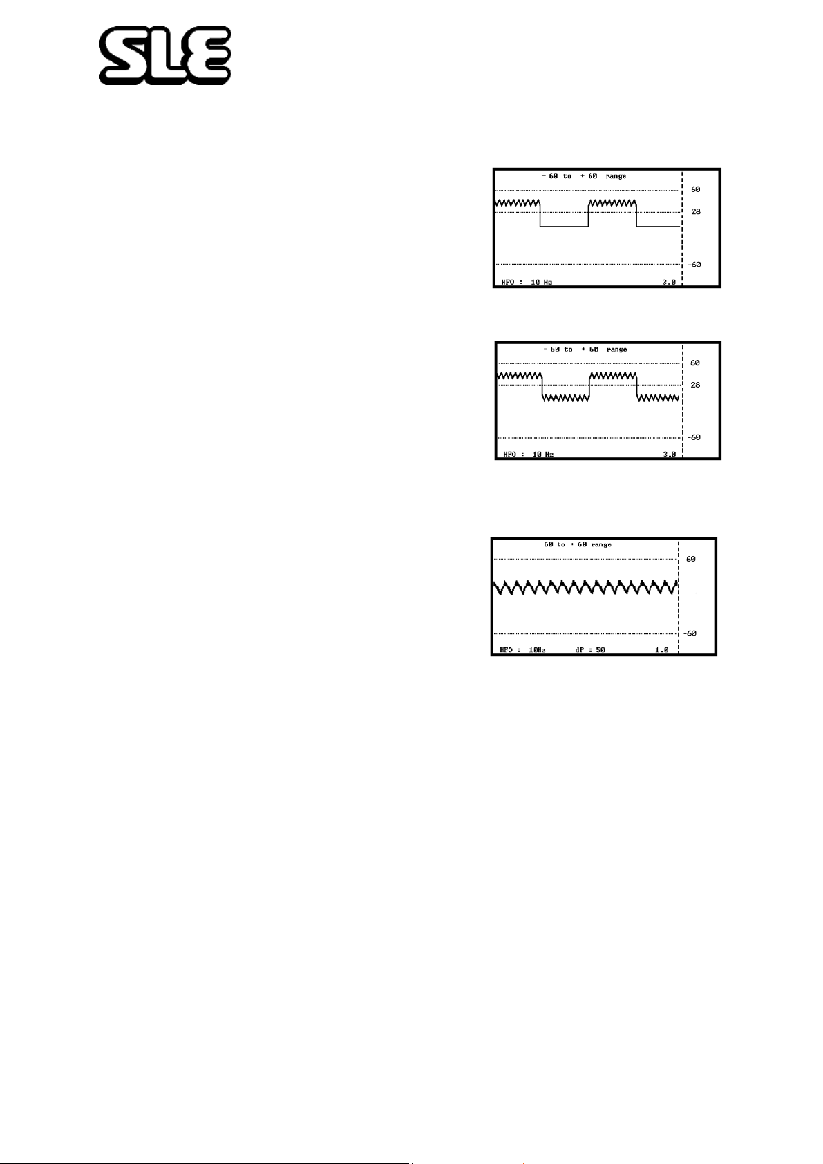
Set HFO mode to INSP
Ensure that :-
• 10 Hz oscillation shown on inspiratory cycle of
waveform.
Set HFO mode to CONT
Ensure that :-
• 10 Hz oscillation shown on both inspiratory and
expiratory cycles of waveform.
Set mode switch to CPAP.
Ensure that :-
• Continuous 10 Hz waveform is seen on the
screen.
Press the reset button to autoset the alarms.
Page 22 of 70
Page 23
Operating Instructions
6.9 Alarm Test
6.9.1 To Verify Alarms
Set the following ventilator conditions :-
• HFO mode OFF.
• CPAP/PEEP regulator to ≈10 cmH2O.
• Inspiratory regulator to ≈30 cmH2O.
• Oscillator Regulator to 0 cmH2O
• Mode switch to CMV
•Rate to 60 BPM
•INSP. TIME to 0.50
• Ensure ventilator is cycling and check the following alarms
• Set Cycle fail alarm to mid waveform
• Reset all alarms
6.9.2 High Alarm
Reduce high alarm setting so that alarm cursor line is below the peak pressure
wave on the screen. This should initiate an audible alarm and a HIGH and LEAK
visual indication. Return alarm setting to maximum position. Reset alarm by the
reset button.
Note: The Fresh Gas flow is reduced from ≈ 5 LPM to ≈1 LPM in the High Alarm
condition.
6.9.3 Cycle Fail Alarm
Increase the alarm setting so that alarm cursor line is above peak pressure wave
on the screen. This will initiate an audible and CYCLE FAIL visual alarm indication.
Return alarm setting to within the pressure wave, audible alarm should self cancel.
Reset visual alarm by the reset button
Decrease the alarm setting so that alarm cursor line is below pressure wave on the
screen. This should initiate an audible and CYCLE FAIL visual alarm indication.
Return alarm setting to within the pressure wave, audible alarm should self cancel.
Reset visual alarm by the reset button.
6.9.4 Low Alarm
Increase low alarm setting so that alarm cursor line is above the minimum pressure
wave on the screen. This should initiate an audible and LOW visual alarm
indication. Visual alarms once set can only be cancelled by pressing the reset
button. Return alarm setting to required position. Reset visual alarm by the reset
button.
Page 23 of 70
Page 24

Operating Instructions
6.9.5 Leak/block Alarm
Disconnect the fresh gas tubing from the ventilator. This should initiate an audible
and LEAK visual alarm indication. Occlude the fresh gas outlet. This should
initiate an audible and BLOCK visual alarm indication. Reconnect tubing, audible
and visual alarms should self reset.
6.9.6 Mains Failure Alarm
DO NOT TURN MODE SWITCH TO OFF).
Disconnect mains power by switching off or removing mains plug from power
socket.
This should initiate an audible alarm. Reconnect mains power supply, ventilator
should carry out self test and resume previous mode of operation.
6.9.7 O2 Blender Alarm
Set Blender to 60%. Disconnect Air supply from wall outlet, an audible alarm
should be heard from Blender. Reconnect Air Supply, alarm should self cancel.
Disconnect O2 supply, an audible alarm should be heard from blender. Reconnect
O2 supply, alarm should self cancel.
6.9.8 Oxygen Concentration Alarm
Set the Oxygen concentration to 60% and press the reset button. Wait 1minute for
the reading to stabilise. Increase the Oxygen concentration to 100%, the alarm
should sound. Decrease the Oxygen concentration to 21%, the alarm should
cancel as the Oxygen concentration crosses the alarm threshold and then sound
again as the Oxygen concentration gets too low. Press Reset.
6.10 O2 Cell
6.10.1 Condition Of O2 Cell.
Set blender to 100% and observe that displayed FIO2 is 100%. Set blender to 21%
and observe that displayed FIO2 is 21%. To adjust, set blender control to 100%.
Remove Air Supply Hose and allow 3 minutes before adjusting control on rear
panel. If unable to set 100%, O2 Cell must be replaced. Ignore any blender alarms
during this adjustment.
Page 24 of 70
Page 25
Operating Instructions
7. Basic Set Up for the SLE 2000 HFO
Warning It is the operator’s responsibility to check the ventilator pressures
prior to changing modes
The ventilator must not be connected to the patient during this set up
procedure.
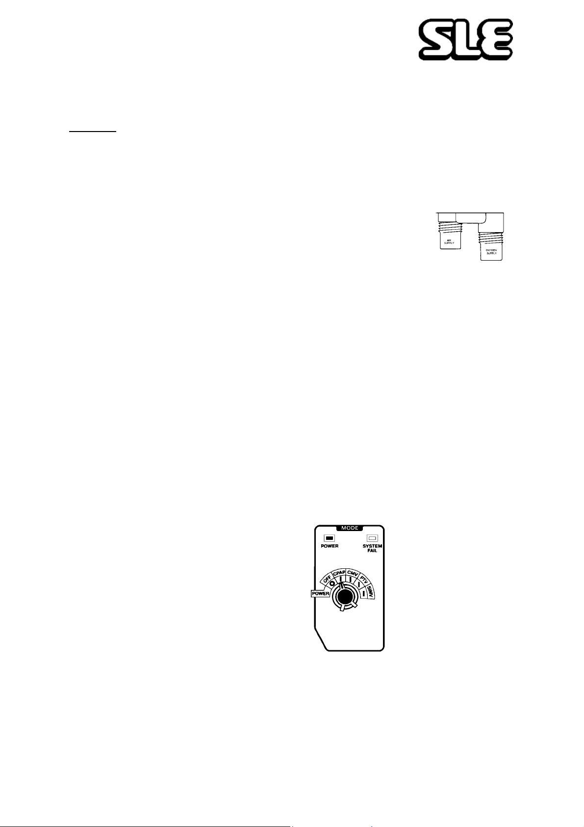
Step 1. Connect AIR and OXYGEN hoses to ventilator and plug into
gas supplies, at a gas pressure of about 4 bar. Connect
mains cable to a suitably rated and grounded electrical
power source.
Step 2. Connect SLE approved patient circuit to the Ventilator and Humidifier.
• For further information see page 47 or instructions supplied with patient
circuit.
• To test the system the patient manifold must be occluded or a Test Lung
fitted.
• Only an SLE approved patient circuit should be used with this equipment
Step 3. Set up humidifier to manufacturer’s instructions
Step 4. Set the following ventilator conditions :-
•High alarm to maximum
•Low alarm to minimum
• HFO mode OFF
• Three pressure regulators to minimum
Step 5. Select mode of ventilation to CPAP
The ventilator will now carry out a self test as described on page 19. Ensure that
this test is completed satisfactorily before continuing.
If after completion of the above self test an alarm continues, a red light might
indicate either BLOCK or LEAK in the fresh gas tubing of the patient circuit. Ensure
that all patient fittings are correctly made and secure.
Page 25 of 70
Page 26
Operating Instructions
Do not continue until alarms are cleared
• The ranges of the graphic display can be set using the display controls. A
FREEZE button allows the waveform to be held. Press to freeze, press again to
un-freeze.
• Do not carry out any adjustments with the display in the freeze mode.
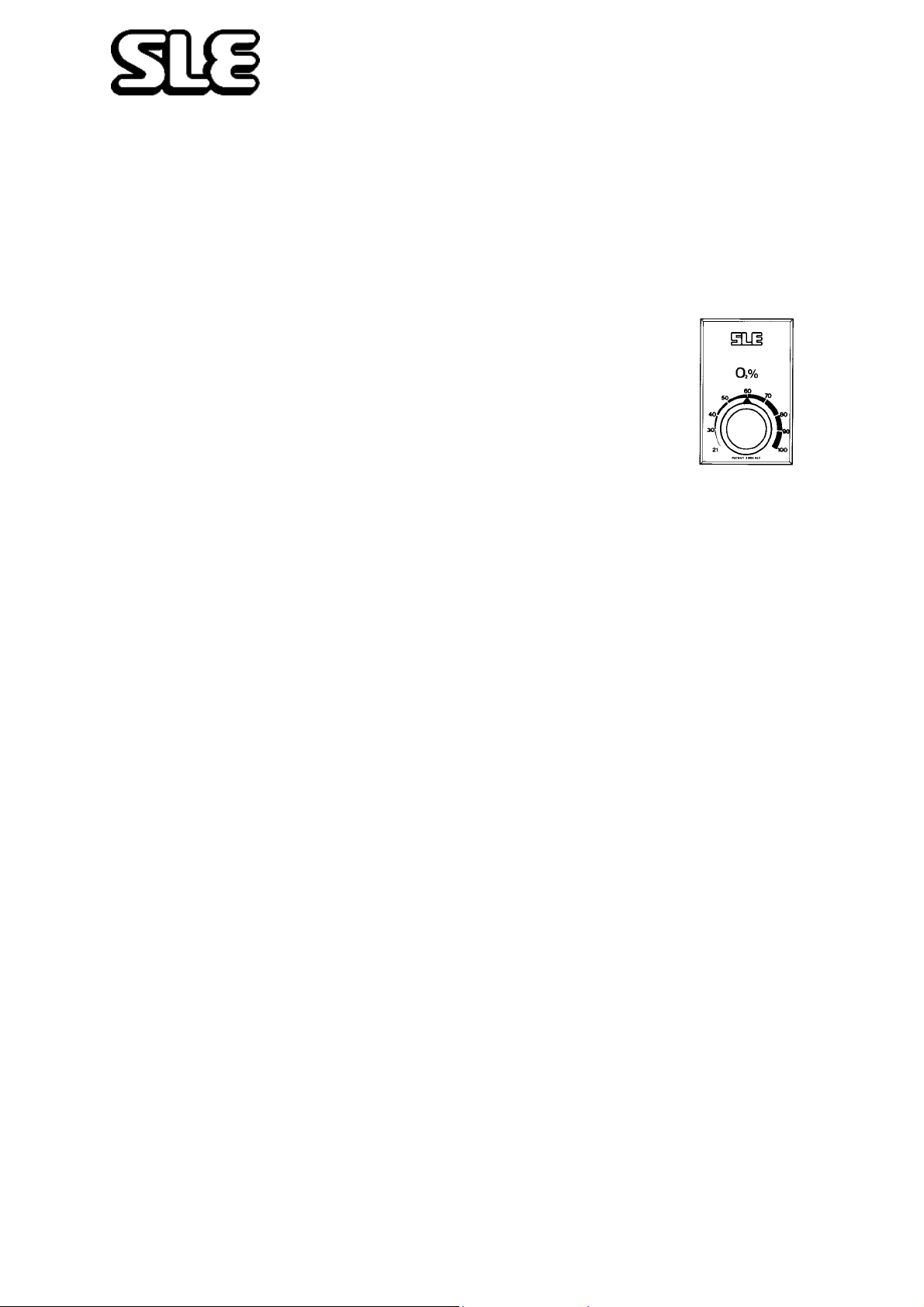
Step 6. (a) Set required O2 concentration by means of O2 Blender
Control. %O2 Oxygen will be monitored and displayed in
Digital Display.
FlO
2
The oxygen monitor will alarm if the oxygen concentration
rises or falls by more than 5% and a warning message will
be displayed on the LCD.
The ventilator should now be ready to connect to a patient.
Changes will take 30 seconds to stabilise on the FlO2 display.
Oxygen - Clinical use. Oxygen is a drug and should be prescribed as such.
Exposing a baby to elevated concentrations may lead to Retrolental Fibroplasia.
Oxygen - Fire Hazard. Oxygen vigorously supports combustion and it s use
requires special precaution to avoid fire hazards. Keep all sources of ignition
away when oxygen is in use. Do Not use oil or grease on oxygen fittings or
where oxygen is used.
Page 26 of 70
Page 27
Operating Instructions
7.1 To Use the SLE 2000 HFO in CPAP Mode
As steps 1 to 6 in basic set-up
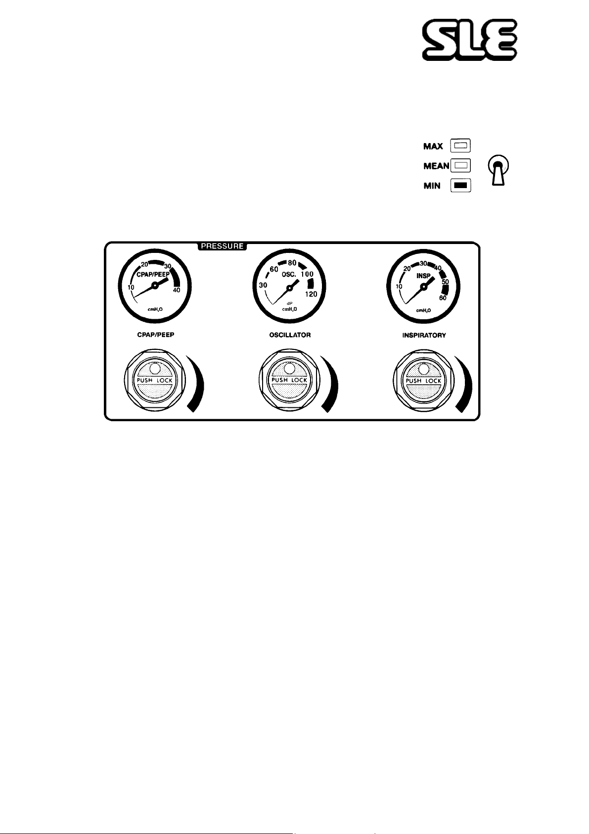
Step 7. (a) Set pressure display switch to minimum
(b) Increase CPAP/PEEP pressure to required level
These Controls are lockable. Push to lock, Pull to unlock.
Pressure will be indicated on the digital display, the graphic display and bargraph.
(c) Set Low alarm to the required level.
The alarm levels are digitally and pictorially displayed on the graphic display.
A manual breath can be delivered, of the set inspiratory time, by pressing the Manual
Breath Button.
Page 27 of 70
Page 28
Operating Instructions
7.2 To Use the SLE 2000 HFO in CMV Mode
As steps 1 to 7 basic set-up and CPAP then:-
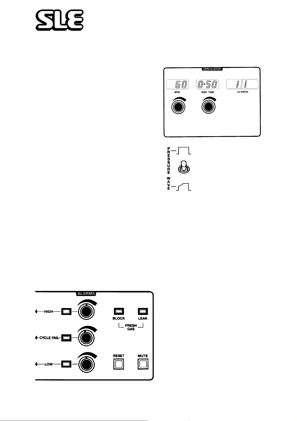
Step 8. (a) Set INSP. TIME to required
rate (displayed in seconds)
(b) Select Pressure Wave Shape
SQUARE or TAPER
(c) Switch mode switch from CPAP to CMV
Note: Ventilator will start to cycle and the alarms will probably sound - press
MUTE to silence them.
(d) Adjust the BPM to required rate.
(e) Set the pressure display switch to MAX and increase the INSP pressure to the
desired level. This is indicated on the digital pressure display, the graphic display
and the bargraph.
(f) Set the CYCLE FA IL and HIGH alarms to required levels. Press RESET to clear
the alarms lights.
HIGH will activate if setting is
exceeded and also open a pressure
relief valve and activate LEAK
alarm
CYCLE FAIL will activate if
pressure wave fails to pass through
threshold on inspiration and
expiration
Page 28 of 70
LOW is activated if pressure
falls below setting
Page 29
Operating Instructions
7.3 Patient Trigger Modes
7.3.1 To Use SLE 2000 In PTV or SIMV Mode
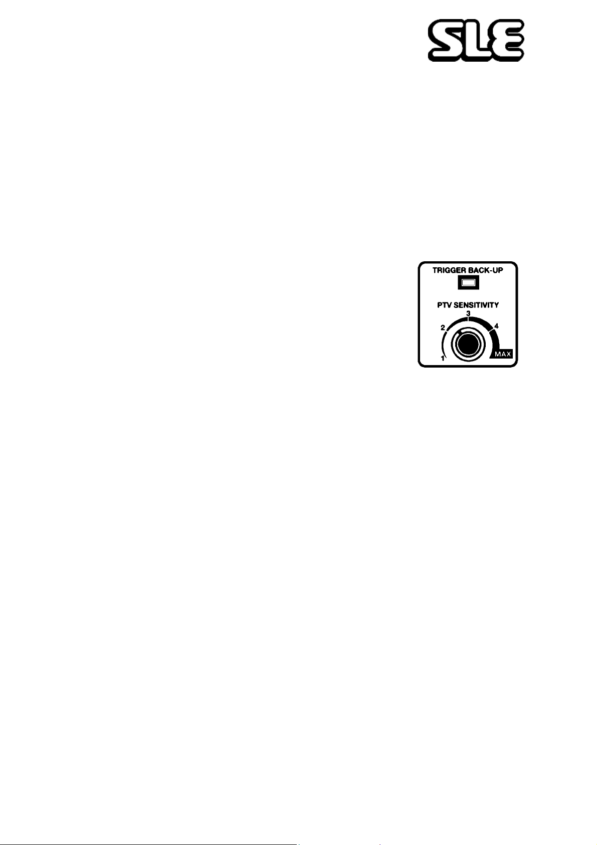
As steps 1 to 7 then:Step 9. (a) Set PTV sensitivity to min
(b) Set the BPM control to provide either:-
The desired back-up rate for PTV
or
The desired number of mandatory breaths per minute for
SIMV
(c) Switch mode from CMV to PTV or SIMV
Once connected to a patient, increase the PTV sensitivity towards Max until patient
effort triggers the ventilator. This is indicated by the TRIGGER BACK-UP light
extinguishing.
• The weaker the patient the higher the sensitivity required.
After 60 seconds with an update every 60 seconds, the BPM LED display will indicate
the number of patient initiated breaths that were delivered in the preceding minute.
Care should be taken not to set the PTV sensitivity too high as it will self trigger.
Page 29 of 70
Page 30
Operating Instructions
7.4 To Use the SLE 2000 HFO in the Oscillator Mode
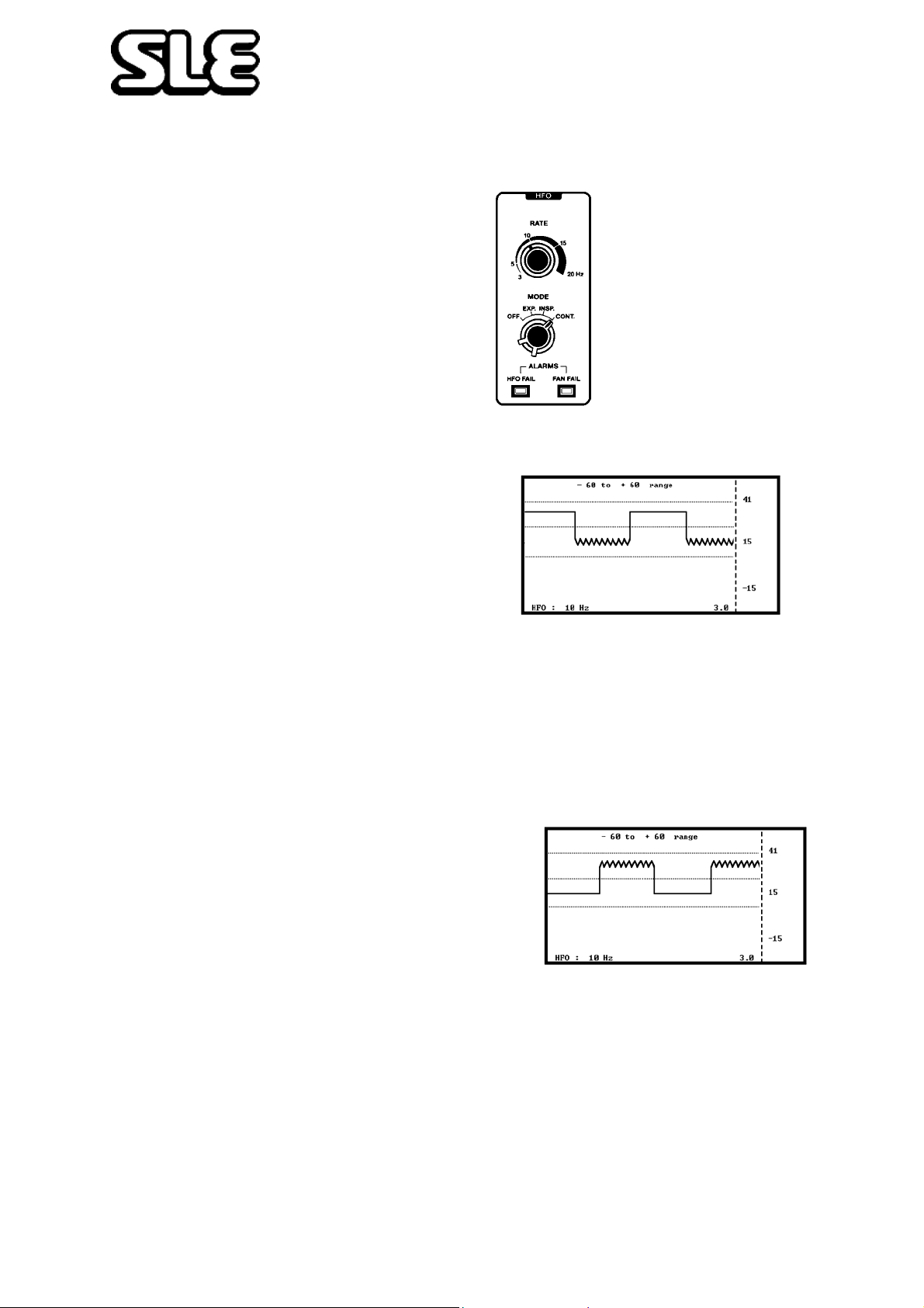
THERE ARE 4 OSCILLATORY MODES
1EXP.
Expiratory oscillation combined with conventional ventilation.
(a) Set ventilator mode to CMV (see
page 28)
(b) Set HFO mode to EXP
(c) Set HFO frequency using rate control.
(d) Set amplitude using oscillation pressure regulator
• Oscillation is added to the conventional pressure waveform. The frequency of
oscillation will be shown on the screen.
2INSP
Inspiratory oscillation combined with conventional ventilation.
(a) Set ventilator mode to CMV (see page 28).
(b) Set HFO mode to INSP
(c) Set HFO frequency using rate control.
(d) Set amplitude using oscillation pressure
regulator
• Oscillation is added to the conventional pressure waveform. The frequency of
will be shown on the screen.
Page 30 of 70
Page 31
Operating Instructions
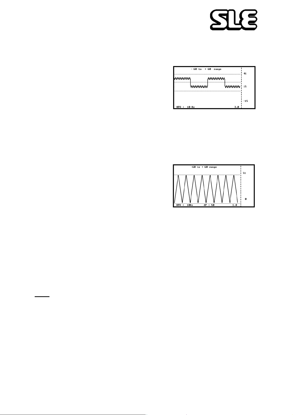
3 CONT. (combined)
Insp+Exp oscillation combined with conventional ventilation.
(a) Set ventilator mode to CMV (see page 28)
(b) Set HFO mode to CONT
(c) Set HFO frequency using rate control
(d) Set amplitude using oscillation pressure regulator
• Oscillation is added to the conventional pressure waveform. The frequency of
oscillation will be shown on the screen.
4 CONT. (oscillation only)
Oscillation only
(a) Set ventilator mode to CPAP (see page 27)
(b) Set HFO mode to CONT
The delta P monitoring system will be activated; see note below
(c) Set the Digital Pressure Display switch to mean
(d) Use CPAP regulator to adjust mean pressure
(e) Set HFO Frequency using rate control and amplitude using oscillation pressure
regulator
(f) Reset the delta P alarm level by pressing the reset button twice
Note. The current delta P amplitude pressure (dP in centimetres of water) will be
displayed on the LCD The function of this monitor is to alarm if the delta P goes too
LOW or display a warning if it goes too HIGH.
The HIGH warning message is “Delta P rise detected push reset to set new alarm
level”
The LOW alarm message is “Delta P drop detected check patient connection”
The alarm cursors can be used as well as the pressure displays to check ventilation
pressures. It is easier to use the display in the ±60 cms mode for oscillation only.
Page 31 of 70
Page 32

Operating Instructions
This page is intentionally blank.
Page 32 of 70
Page 33
Technical Information
Page 33 of 70
Page 34
Technical Information
8. Ventilator Controls
8.1 Electronic Module
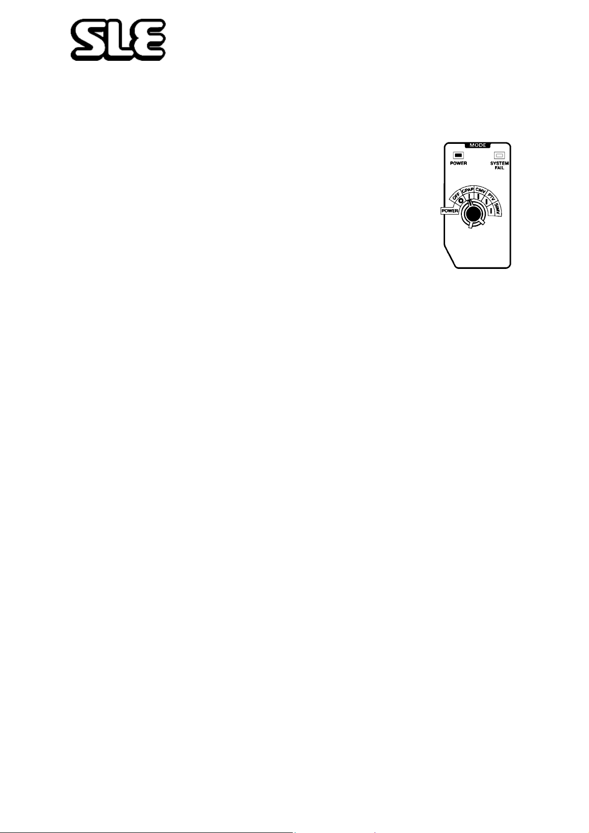
8.1.1 Mode Switch (5 positions)
OFF- CPAP- CMV- PTV- SIMV
• OFF = All electrical power off.
Note: There is a limited fresh gas supply with mode switch in the
OFF position, if ventilator is used with Head boxes etc. switch to
CPAP.
Switching to CPAP. CMV. PTV or SIMV (power on),
Power LED shows green and an automatic test of functions & alarms is initiated.
Firstly the displays and audible alarms are turned on for approximately two seconds
to demonstrate that they are operable, then for a further three seconds all the digital
displays show a sequence of numbers from O to 9 before returning to their normal
state.
Note: HFO Fail, Fan Fail and Block LEDs do not come on during this sequence.
8.1.2 System Fail LED
Lights if main microprocessor system or other electronic circuitry fails (See
“Alarms” on page 42.)
8.1.3 CPAP Mode
Activates INSP. Time control (for Manual Breath) and digital display, FlO2, mean
and min airway pressure digital displays. Also activated is the Manual Breath push
button and associated with it the 'High', 'Low', 'Failure to Cycle' and 'Fresh Gas'
alarms. The mean airway pressure in CPAP will show an average of airway
pressures.
8.1.4 CMV Mode
Additionally enables the BPM control and INSP. TIME controls to set and display
the rate and MIT of the ventilator cycles, and from these settings calculates and
displays the l:E ratio.
• If these controls are set outside valid safety limits their respective displays will
flash. The position of last control adjusted should be decreased to bring the
adjustment to valid safety settings and stop the display from flashing.
Page 34 of 70
Page 35

Technical Information
8.1.5 PTV Mode
BPM control no longer functions in this mode. The last BPM
setting in CMV, prior to switching to PTV will be the back-up
rate. (Setting a time window for Apnea). Additionally the PTV
sensitivity control is activated, all inspiratory efforts at
chosen sensitivity should trigger the ventilator.
However, if the sensitivity is set too low , or the p atient fails to
make an inspiratory effort during the back-up time window,
the ventilator will deliver a back-up breath and indicate this by the TRIGGER BACK
UP LED. If the sensitivity is set too high the ventilator could self trigger at a high
rate.
After 60 seconds with an update every 60 seconds, the BPM LED display will
indicate the number of patient initiated breaths that were delivered in the preceding
minute.
In this mode inspiratory times of less than 0.5 seconds are recommended.
• In PTV mode the BPM display will show only patient initiated breaths. To check
back up rate it is necessary to change the mode switch temporarily to CMV.
• To enable an audible back-up bleep, hold the Reset button in during the automatic
test mode on power up.
Note: PTV has a default of 12 breaths per minute, if the mode switch is turned
straight to PTV mode with out stopping on CMV mode to set the back up breath
rate.
This is also the case if there is an interruption to the power supply, the
ventilator will also default to this setting. It will be necessary to change the
mode switch temporarily to CMV to reset the required BPM.
8.1.6 SIMV Mode.
This mode enables BPM control to select and display the maximum number of
breaths, triggered or untriggered, to be delivered by the ventilator.
If the patient fails to trigger the ventilator during the first half of the SIMV time
window, the ventilator will immediately deliver a mandatory breath indicate this with
an audible bleep. Any additional spontaneous breaths by the patient will be
unsupported by the ventilator.
• To enable an audible back-up bleep, hold the Reset button in during the automatic
test mode on power up.
Page 35 of 70
Page 36
Technical Information
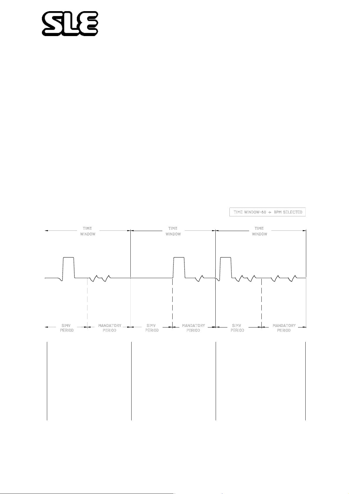
The SIMV mode of the SLE 2000HFO functions in the following manner:
The BPM control setting will determine the number of breaths that will be supplied in
each minute. In the period between each of these breaths a time window is opened.
During the first half of this time window, should the patient attempt to make an
inspiratory effort the ventilator will deliver a single synchronised mandatory breath. If,
however, after the first half of this time window has elapsed the patient has made no
detected effort to breathe the ventilator will then supply a single unsynchronised
mandatory breath and make a short audible bleep.
It is possible to disable the audible bleep made on each mandatory breath in the SIMV
mode. Whilst switching the ventilator mode switch from the OFF position to SIMV, and
during the initial ventilator system check, when the digital displays run the their
numerical check, the RESET button is held in. This will disable the audible bleep, until
the ventilator is switched OFF again.
The ventilator will only supply one breath during each time period set by the BPM rate.
So the total number of breaths delivered either synchronised or mandatory will be only
that shown in the BPM display.
If an inspiratory effort is
detected during SIMV
period, ventilator will
deliver a synchronised
breath. All further
spontaneous breaths
during this time window
are not assisted.
Page 36 of 70
If patient fails to make an
effort during SIMV
period, ventilator will
deliver a mandatory
breath at start of
mandatory period, any
further efforts during
time window are
ignored.
Patient triggers breath at
start of time window and
ventilator will ignore all
breaths until this time
window has elapsed.
Page 37
Technical Information
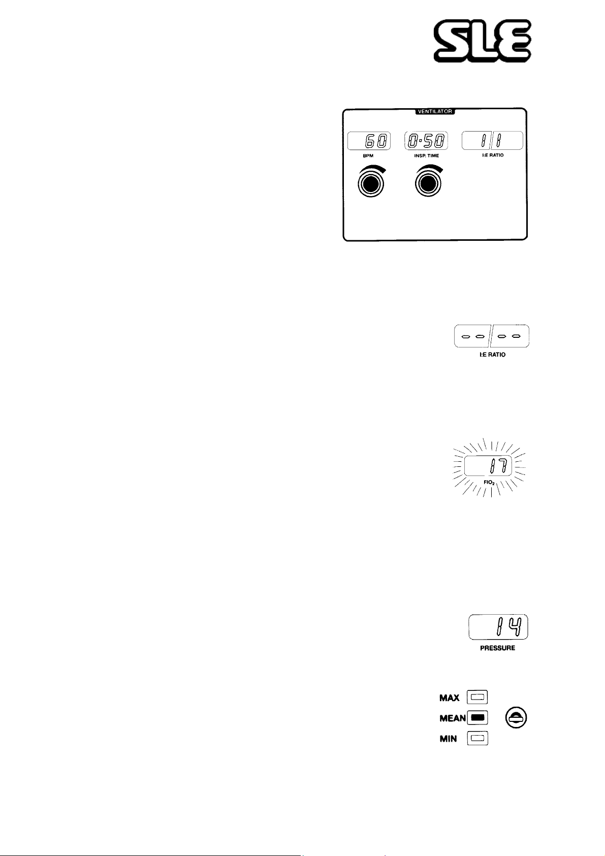
8.1.7 BPM
Ten-turn control with LED digital indication to
set the breath rate per minute.
8.1.8 Inspiration Time
Set by ten-turn control with indication on 3
digit LED display showing the set value in
seconds.
Invalid settings of the BPM. and INSP. TIME
controls are indicated by these two displays
flashing. The ventilator will not allow the expiration time to be set to less than 0.25
seconds.
8.1.9 I:E Ratio
This appears on a four digit LED display and is calculated from the
settings of the BPM and the INSP. TIME controls.
• If the BPM and the INSP TIMES are set so that the l:E ratio exceeds 9.9:1 or 1:9.9,
the display will show four dashes. This will also occur in the PTV Mode.
8.1.10 Oxygen (FlO2)
Indication of the oxygen concentration of the Fresh Gas supply to
the patient appears on a 3 digit LED display . Should the indication
fall below 18% the display will flash. The oxygen monitor will
alarm if the oxygen concentration rises or falls by more than 5%
and a warning message will be displayed on the LCD.
• Recalibration at 100% O2 is effected by rear panel screwdriver adjustment. See
section 11. on page 46
8.1.11 Pressure Display.
Digital LED indication ±65 cm/H20
8.1.12 Three Position Switch.
For selecting display of MAX (maximum),
MEAN, or MIN (Minimum) airway pressures.
Page 37 of 70
Page 38
Technical Information
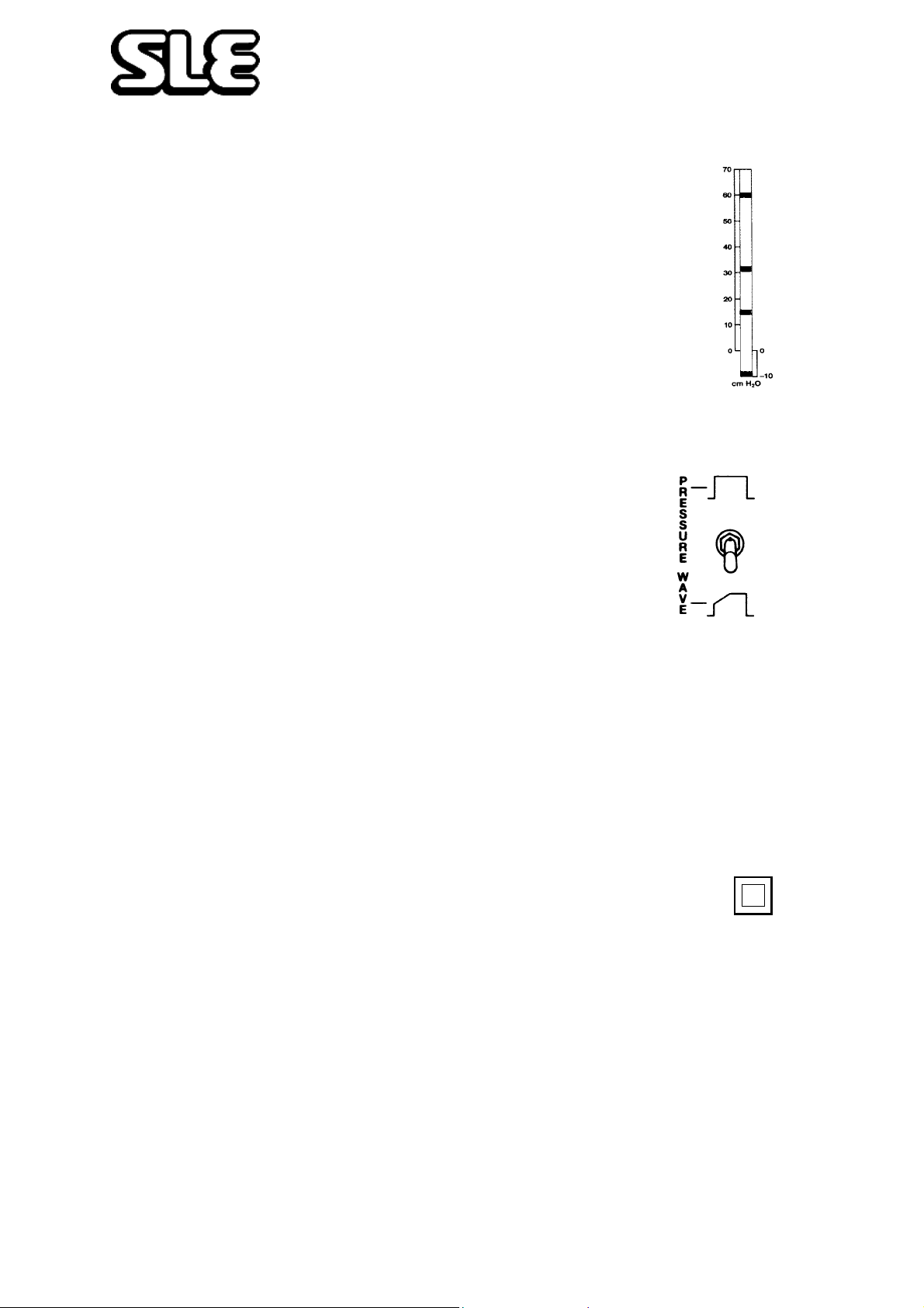
8.1.13 Pressure Display Bargraph.
Shows pressure and selected alarm settings -10 to +70 cms
8.1.14 Pressure Wave Switch
This switch alters the pressure waveform from SQUARE
to TAPERED as indicated.
• This is an Automatic Locking Toggle Switch. Pull toggle lever to release.
• The ventilator should be set to a square waveform for breathing rates above 60
BPM.
8.1.15 Manual Breath
The manual breath push button functions in the CPAP, CMV and
PTV modes, with the High pressure and Failure to Cycle alarms
operative. Manual breath button is inoperative in any HFO mode.
Manual Breath
• Manual breath duration = INSP. TIME setting
Page 38 of 70
Page 39
Technical Information
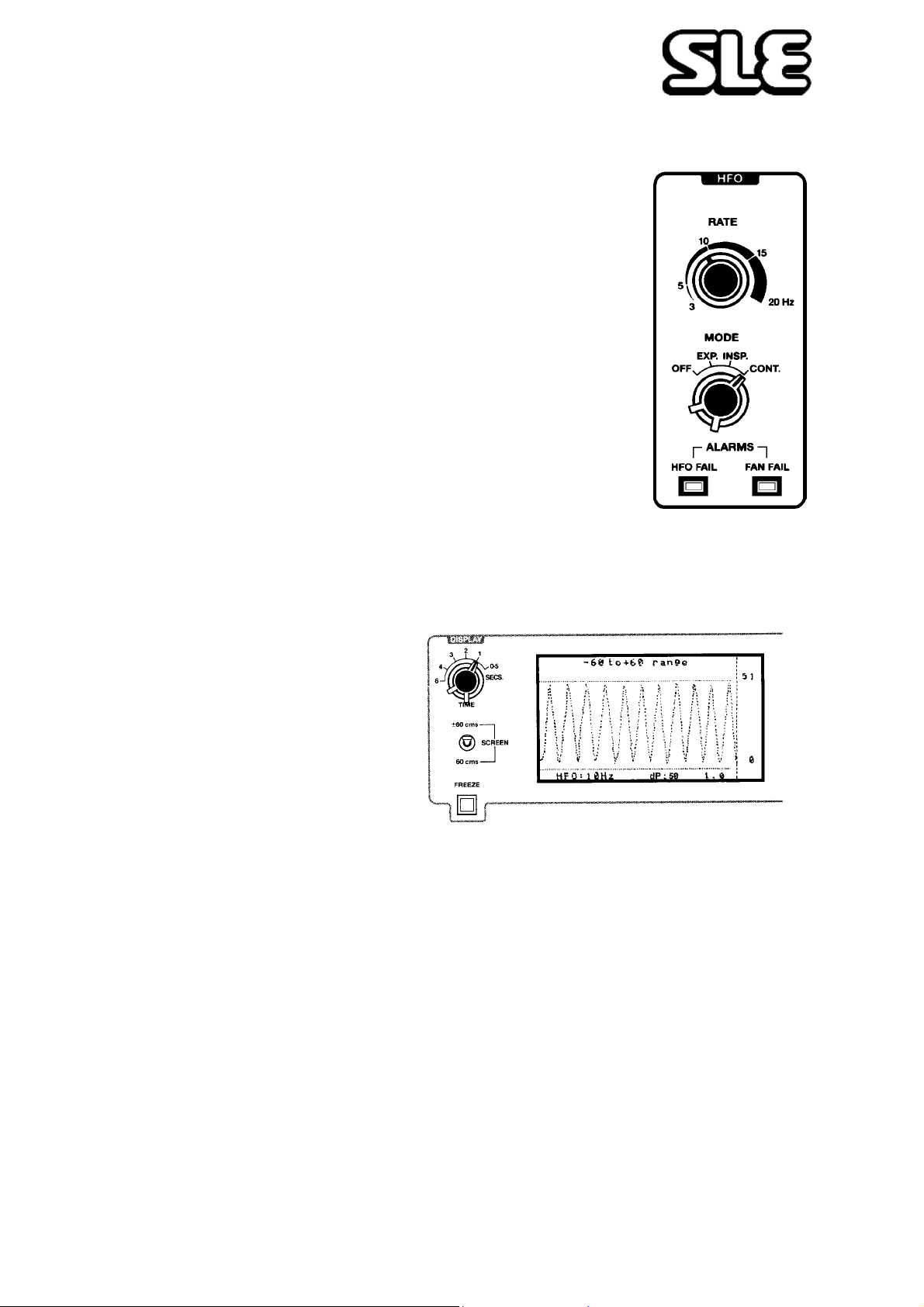
8.1.16 HFO Controls
Mode. Four positions.
OFF - EXP- INSP - CONT
Oscillation is provided on the expiratory, inspiratory and
expiratory/inspiratory parts of the pressure wave. Continuous
oscillation can also be provided by selecting CONT on the
HFO mode control and CPAP on the MODE control.
Rate
Controls the frequency of HFO oscillation in Hertz. Oscillation
rate is displayed on the screen.
8.1.17 Time Control Switch
Choice of the time for one
complete sweep across the
screen. Selectable between
0.5 to 6 seconds in six setting.
Note: In HFO mode, positions 4 to 6 do not have any effect. The display will
remain set at 3.
8.1.18 Screen Switch
Controls the range of the screen display between -5 to 60 cms and ± 60 cms.
Use -5 to 60 cms for ventilation or ventilation/oscillation modes.
Use ± 60 cms for oscillation mode only.
8.1.19 Freeze
Will freeze screen for up to 1 minute. Can be reset at any time by pressing the
freeze switch again.
Page 39 of 70
Page 40
Technical Information
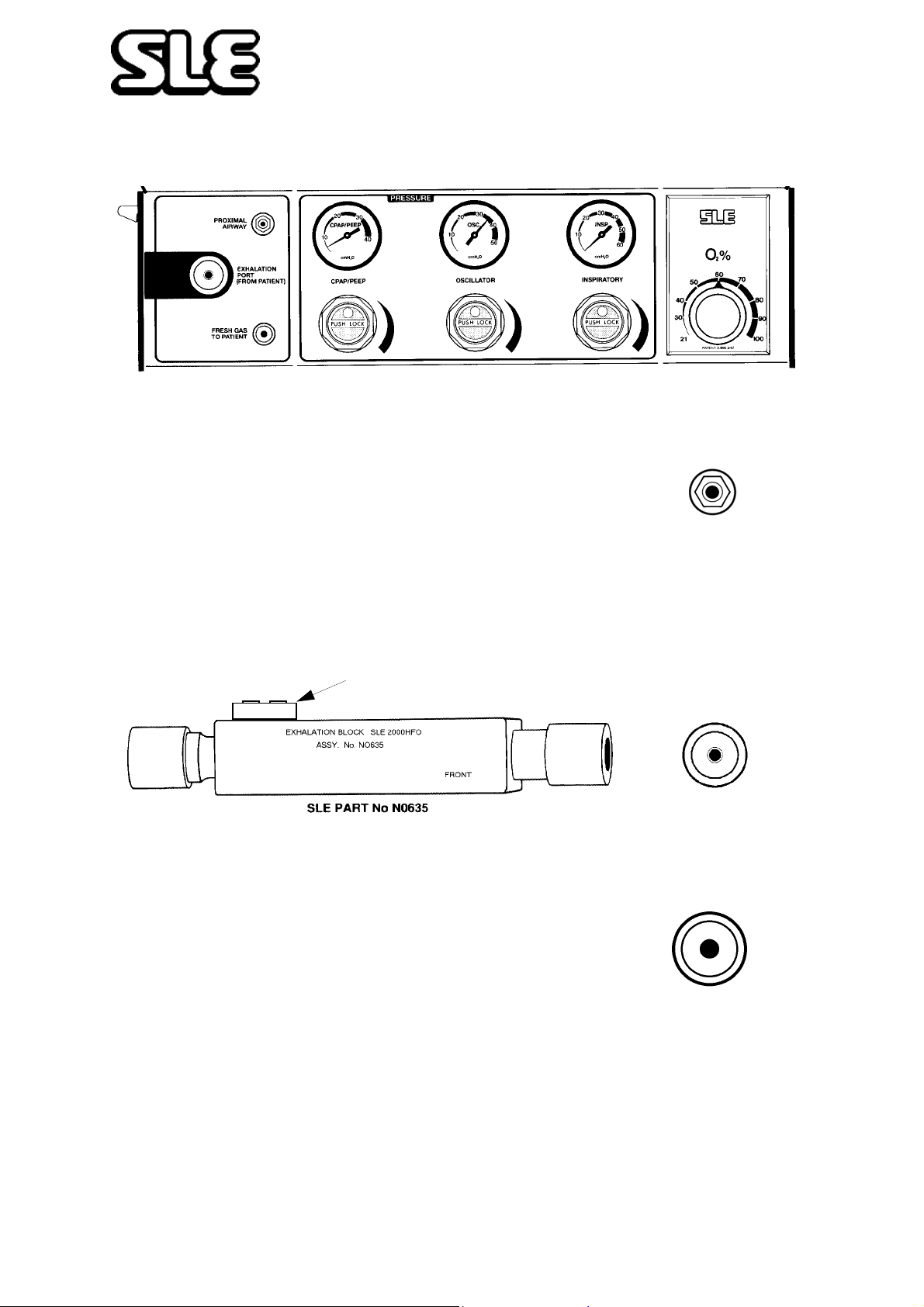
8.2 Pneumatic Module
8.2.1 Proximal Airway
Input from patient ET connector to pressure display bargraph and
internal pressure transducers.
8.2.2 Removable Exhalation Block
Can be removed easily for cleaning by lowering side panel.
.
PRESSURE
RELIEF VALVE
8.2.3 Fresh Gas Port
The Fresh Gas port supplies 5 LPM of the blended gas via the
humidifier to the patient inspiratory port on the ET connector.
Page 40 of 70
Page 41
Technical Information
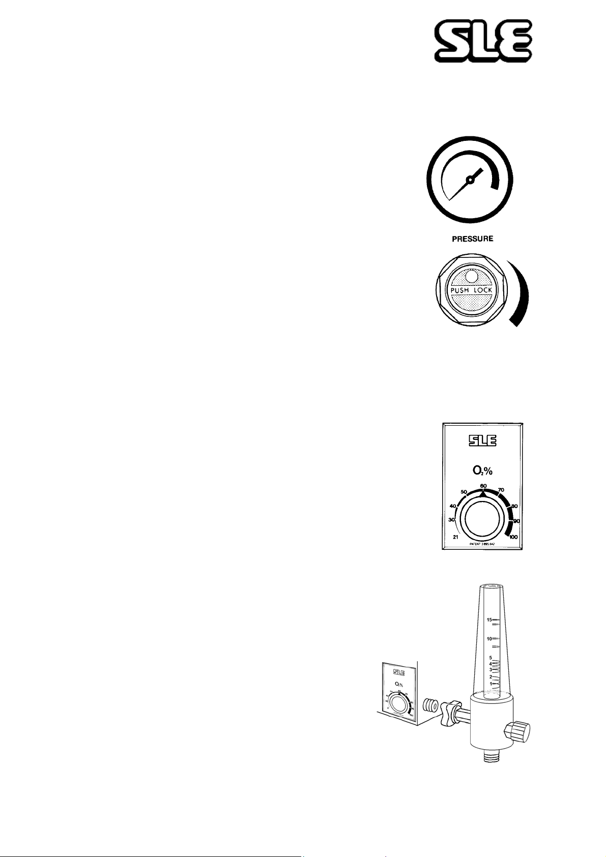
8.2.4 Regulator and Pressure Gauges
8.2.4.1 CPAP
This regulator controls the base pressure in the circuit. In
HFO mode this control will be used to set the mean pressure.
8.2.4.2 Oscillator
This regulator controls the amplitude of the oscillatory
pressure.
8.2.4.3 Inspiratory
This regulator controls the peak inspiratory pressure (PIP).
These 3 pressure regulator controls have push/pull locking
caps.
8.2.5 O2 Blender (% FlO2)
The oxygen blender controls the amount of oxygen available in
the fresh gas supply. The blender is monitored separately by an
internal analyser and displayed on the FlO2 digital display.
There is an option (Option 3) for a blended gas
output connected on the side of the unit.
Note: This output provides up to 15 LPM Blended
gas controlled by the O2% control
Page 41 of 70
Page 42

Technical Information
9. Alarms
Warning Audible and V isual warning alarms indicate a potentially harmful
condition to the patient. Failure to t ake corrective action could result in injury or
death to the patient.
9.0.1 Microprocessor
The microprocessor system failure and other electronic circuitry failures are
alarmed as follows.
The microprocessor carries out a self check every 20 mS, and should a failure be
detected the 'SYSTEM FAIL' LED will start to flash and the processor will attempt
to reset itself. There is a secondary watchdog alarm independent of the above
system which is reset by the main processor every 20 mS. Should the processor
fail to reset this watchdog within 3 seconds then a HIGH FREQUENCY alarm will
pulse at 2 Hz. This alarm can only be cancelled by switching the ventilator off.
Other hardware system checks are incorporated such as the
monitoring of the solenoid driver circuitry. If the solenoid driver
fails to operate when the processor has initiated a solenoid
valve closure or opening, 'SOL' will appear in the BPM display
window. All the front p anel potentiometers are frequently
checked for continuity . If a defect is found then, 'HELP' appears
in the l:E ratio display window and the solenoid is de-energised.
Further checks are made on the processor associated hardware, and again if any
fault is detected the solenoid is de-energised and ‘HELP’ is displayed in the l:E
ratio display window.
9.0.2 Mains Failure Audible Alarm
Active when the mode switch is in any position except OFF and will alarm if mains
voltage supply fails.
9.0.3 Gas Supply Failure Alarm
The Air and Oxygen audible alarms are an integral part of the blender, and function
when AIR or O2 pressures differ by more than 30 PSI.
Page 42 of 70
Page 43
Technical Information
9.0.4 Fresh Gas Fail Alarm (Block & Leak)
This fresh gas failure system will detect either a blockage or a leak in the Fresh Gas
supply line.To achieve this there is a small restrictor fitted in the inspiratory limb of
the patient circuit, creating a pressure in the alarm circuitry to the Electronics
Module. Should the Fresh Gas supply to the patient fail, visual and audible alarms
will activate. The Fresh Gas LEAK LED will illuminate and the audible alarms will
operate. This alarm will reset when the gas flow is restored. Similarly the Fresh Gas
BLOCK LED will illuminate and the alarm will sound, should there be a blockage in
the patient gas supply, and a high pressure relief valve will be activated.
9.0.5 HFO Fail
Audible and visual alarm indicating that the oscillator motor has failed therefore
cutting off oscillation.
9.0.6 Fan Fail
Audible and visual alarm indicating that there has been a fan failure.
9.0.7 Adjustable Alarm
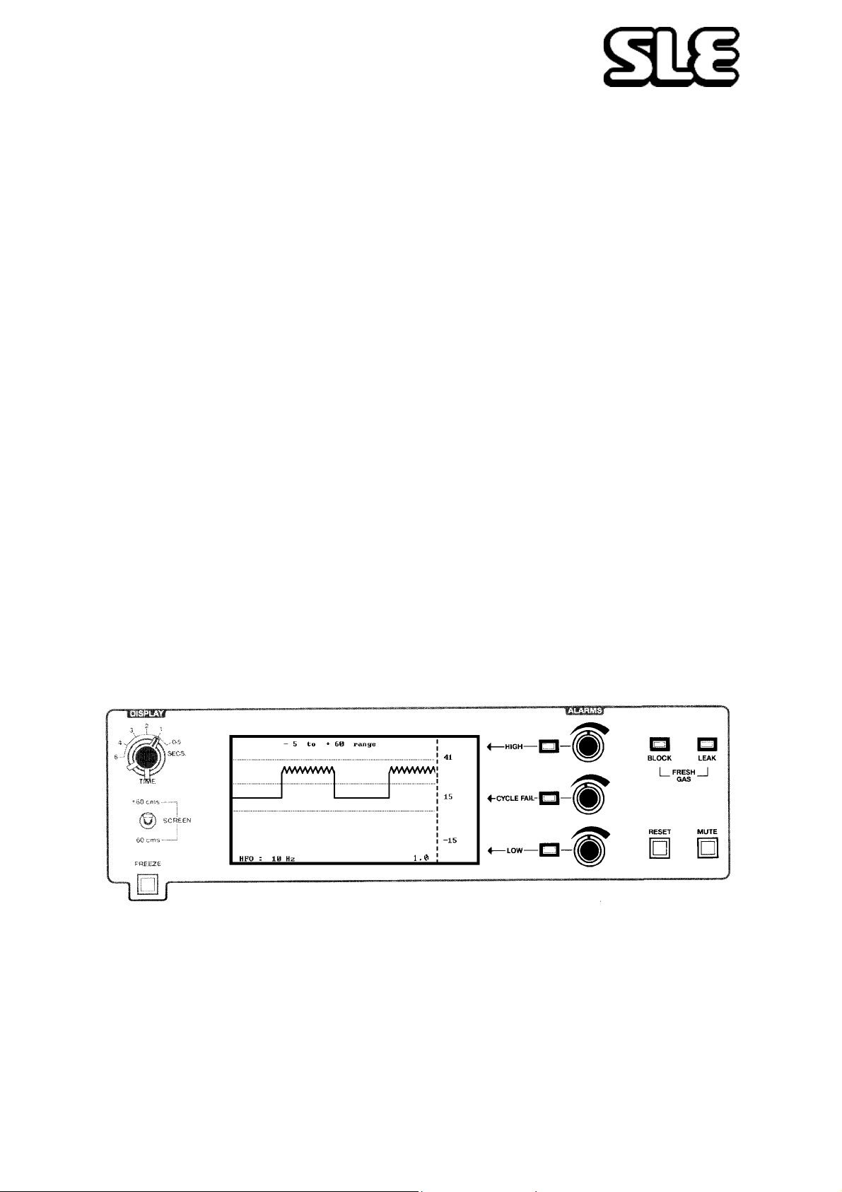
Three controls on the front panel control the settings for HIGH, CYCLE FAIL and
LOW alarms. Settings are indicated by numeric displays and cursor lines on the
screen. They are also shown on the Bargraph Display.
9.0.8 High Alarm
Should the airway pressure exceed the HIGH alarm setting, audible and visual
alarms will be activated, a system leak will be introduced to vent excessive pressure and the fresh gas supply will be cut off. HIGH pressure alarms can only be
cleared and fresh gas returned by reducing airway pressure then pressing the reset
button.
Page 43 of 70
Page 44

Technical Information
9.0.9 Cycle Fail Alarm
This alarm will be activated should the pressure wave fail to pass through the
CYCLE FAIL alarm setting on either inspiration or expiration, indicating a drop in
airway pressure, a leak or circuit blockage. The audible alarm will reset
automatically on correct pressure being restored but the visual alarm must be
RESET by pressing the reset button.
9.0.10 Low Alarm
Should the circuit pressure fall below the LOW alarm setting then an audible and
visual alarm will be activated. The audible alarm will reset automatically on correct
pressure being restored but the visual alarm must be reset by pressing the RESET
button.
9.0.11 Delta P Alarm
This alarm will only become operative when the ventilator is in “Oscillation only”
mode (see page 31). The alarm is reset when the RESET button is pressed twice. It
will alarm if the DELTA P pressure rises by more than 10% above the level it was
when the alarm was set. A warning will be displayed on the LCD if the DELTA P
pressure drops by more than 10% below the set level.
9.0.12 O2 BLender Alarm
This is a mechanical alarm and will sound when the pressure difference between
the supply gasses is greater than 30psi, indicating a possible gas supply failure.
9.0.13 Oxygen Alarm
This alarm will sound if the oxygen level changes by 5 percentage points from the
level it was 60 seconds after reset was last pressed. A message is displayed on the
LCD indicating whether the oxygen level is high or low.
9.0.14 Alarm Mute
This button will mute the audible alarms of PATIEN T GAS FAILURES, CYCLE
F AIL, LOW, and HIGH PRESSURE for a period of 60 seconds, but can be reset by
the RESET push button, providing no alarm condition exists.
9.0.15 Alarm Volume
The main high frequency alarm volume is factory pre set. It is not user adjustable.
9.0.16 Alarm Verification
For the procedure for verifying the alarms (See “Alarm Test” on page 23.)
Page 44 of 70
Page 45

Technical Information
10. Auxiliary Output
Warning No external voltage should be applied to the auxiliary socket. Any
connections to this socket must be approved by SLE and screened to comply
with EMC regulations. Ensure protection cap is fitted when socket is not in use.
Analogue signal outputs are available at the rear of the electronics module, on the 7
pin DIN connector Auxiliary O/P.
Buffered airway pressure. Pin 1 0.42 - 6.42 volts and corresponds to ± 60
cmH2O
FIO
2
Common ground. Pin 3
INOSYS Shut off connection Pin 4 5V= No Alarm 0V = High alarm condition
All other pins must be left unconnected.
• Only SLE approved equipment may be connected to this auxiliary output socket.
Pin numbering as viewed from the outside of the Ventilator
Pin 2 0 - 4.5 volts and corresponds to 0 to 100%
Page 45 of 70
Page 46
SLE
232 SELSDON ROAD
SOUTH CROYDON
SURREY CR2 6PL U.K.
TYPE Nº
SERIAL Nº
SUPPY V ~ Hz
POWER A
CLASS TYPE
Fan Filter
Technical Information
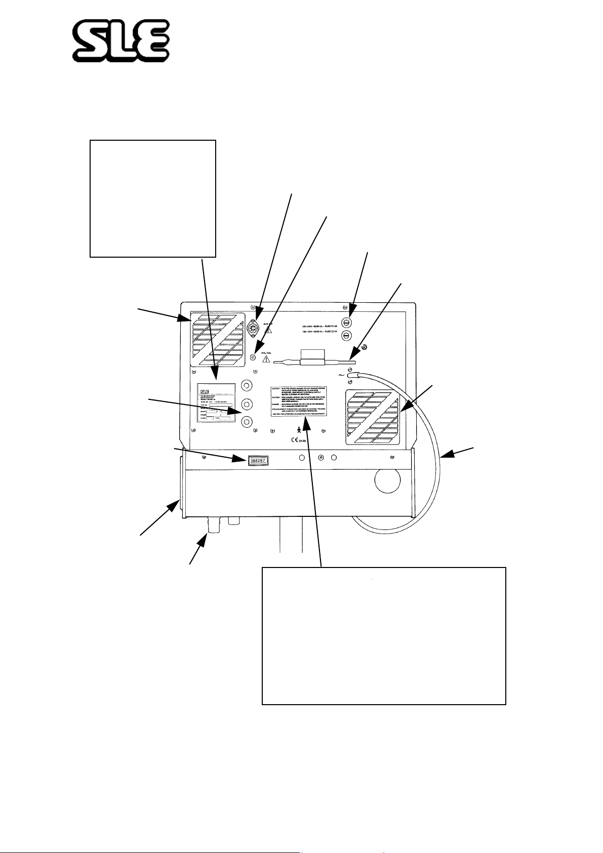
11. Rear Panel
Auxiliary Output Connector
FI0
100% Adjustment
2
FuseHolders
FI0
100% Adjustment Tool
2
Alarm Sounder
Running Time indicator
Fan Filter
Gas Inlet Ports
Fan Filter
Mains Cable
CAUTION- ELECTRIC SHOCK HAZARD. DO NOT REMOVE COVERS
PERSONNEL.
DISCONNECT ELECTRICAL SUPPLY
CAUTION- FIRE HAZARD. ENSURE FAN OUTLETS ARE FREE FROM
DANGER - EXPLOSION HAZARD. DO NOT USE IN THE PRESENCE
THIS EQUIPMENT SHOULD ONLY BE USED BY SUITABLY TRAINED
AND CLINICALLY AUTHORISED PERSONNEL.
OR PANELS. REFER SERVICING TO QUALIFIED
BEFORE SERVICING
OBSTRUCTION. CHANGE FAN FILTERS REGULARLY
(SEE USER MANUAL)
OF FLAMMABLE ANAESTHETICS.
Page 46 of 70
Page 47
Technical Information
12. Patient Circuit Connection
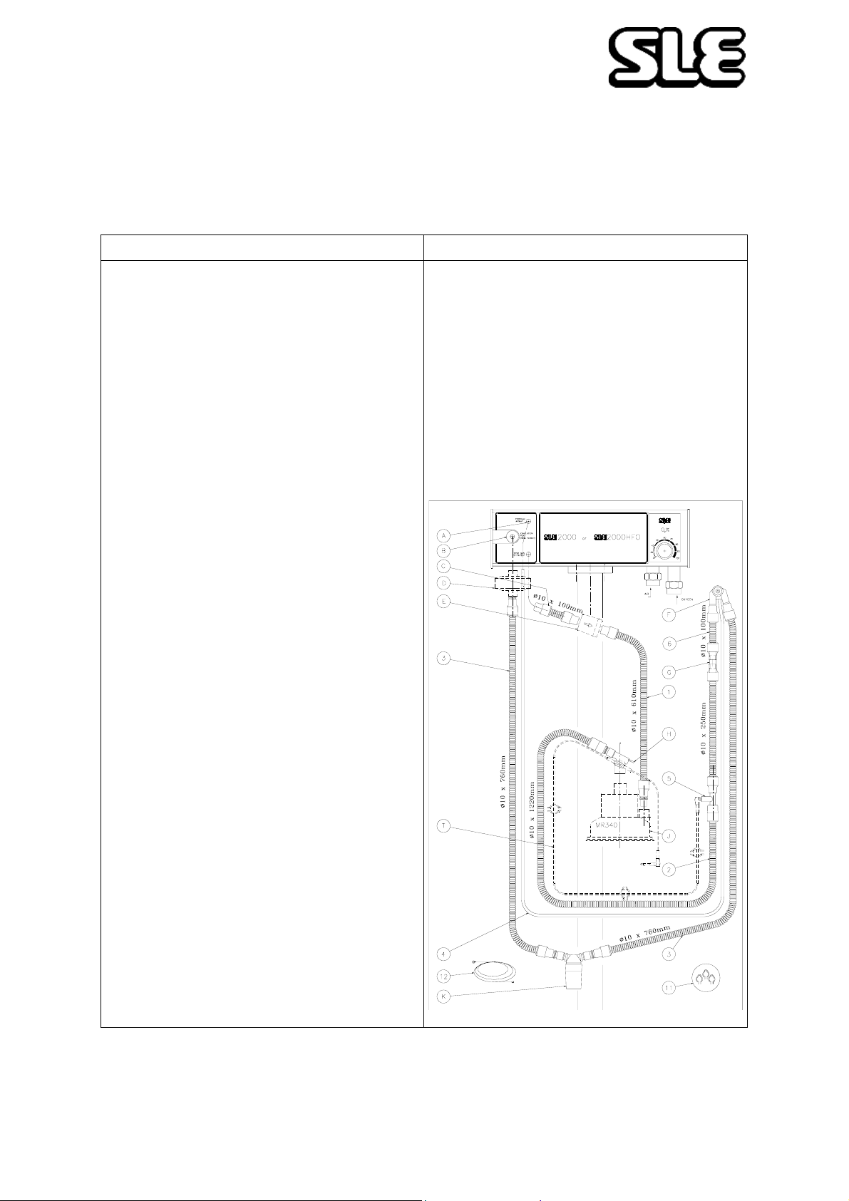
RE-USABLE PATIENT CIRCUIT (SLE Part Nº N2391)
This circuit must be clean and sterilised before use. It is designed to be used
with an SLE 2000 or SLE2000HFO Infant V entilator in combination with a Servo
controlled humidifier- typically a Fisher and Paykel or equivalent.
Directions For Use Cautions
Clean and sterilise before and after subsequent use of 7 days
maximum. It is recommended that a high quality bacteria filter (SLE
part no. N2029) is fitted at the fresh gas connection to the humidifier
inlet, however the circuit may be used without. Connect the patient
circuit as shown in the diagram and described below. Drain water trap
regularly by removing the bottom cup. (Circuit pressure is not lost
when cup is removed).
1) HUMIDIFIER SUPPLY LINE
If a bacteria filter is being used, fit the short piece of tube ITEM C to
the ventilator outlet marked ‘Fresh Gas to Patient’. Fit the bacteria
filter into this tube. Take the loose length of tube ITEM 1 and connect
the free end of this to the bacteria filter and the adaptor end to the
humidifier inlet. If a bacteria filter is not bein g used , connect the loose
length of tube ITEM 1 directly between the ‘Fresh Gas to Patient’
ventilator outlet and the humidifier inlet.
2) INSPIRATORY SUPPLY LINE
Take the main patient circuit and fit the tube with the large connector
to the humidifier outlet. Plug the humidifier heated wire supply onto
electrical connector ITEM H
3) EXPIRATORY SUPPLY LINE
Take the tube with the connector and fit to the exhalation port of the
ventilator. Position water trap in an upright position at the lowest point
in the circuit limb.
4) PROXIMAL AIRWAY PRESSURE LINE
Connect the small diameter clear tube from the patient circuit to the
proximal airway port on the ventilator.
5) TEMPERATURE MONITORIN G
Two ports are provided for dual temperature probes, one in the
connector on the humidifier outlet (next to the heated wire inlet) and a
second port in the tube tee ITEM 5.
STERILISING (Maximum Temperature 134°C)
Dismantle circuit parts and water container for cleaning. Steam
autoclave only, at a recommended temperature of 121°C for 20
minutes. Allow 15 minutes dry time and return to ambient temperature
before assembly and use.
DIAGRAM INDEX
A Proximal Airway Inlet
B Exhalation Port (From Patient)
C Ø10 x 100 Tube Assembly Pt Nº.N2998/04
D Single Use Bacteria Filter - Optiona l Pt Nº.N 2187 or N2587
E Autoclavable Bacteria Filter - Optional Pt Nº.N2029
F ET ManifoldPt Nº.N3145
G Red Metal Restrictor Pt Nº.N2266
H Heater Connection - Dual Servo Hose AssyPt Nº.N3510
J Humidifier Chamber - Reference only
K Water Tr ap Pt Nº.N3139 (See Separate Instructions)
T Temperature Probe - Refe rence only
1 Humidifier Supply Line - Ø10 x 610 Tube Assy Pt Nº.N2998/24
2 Inspiratory Supply Line - Ø10 x 250 Pt Nº.N2998/10 & Ø10 x 1220
Pt Nº.N2998/48
3 Expiratory Supply Line - Ø10 x 760 Pt Nº.N2998/30 (x2) + Adaptor
No.N3148 (x5)
4 Proximal Airway Pressure Line - i/Ø 1/8” x o/Ø 1/4” x 1830...Pt
Nº.N2030
5 Temperature Monitoring - Probe Housing Unit Pt Nº.N3146
6 Inspiratory Supply Line - Ø10 x 100Tube assemblyPt Nº.N2998/
04
11 Hose Clips - Secure Temperature Probe Lead Pt Nº. N3049
12 Draw Wire - Tool for Assembly of Heater Wire Pt Nº.N3071
• Make sure that all connections are made properly and are
tight before use.
• For circuit heating, follow the directions provided with the
humidifier
• Do not use in applications where gas temperature at outlet
of humidifier exceeds 55
o
C.
• Do not cover the circuit with anything which may cause the
tube to overheat.
• Do not autclave water trap if medications containing
chlorinated or aromatic hydrocarbons are used.
• Avoid resting the patient circuit against patient skin
• Keep water trap upright with cup at bottom. Empty
container before water reaches MAX Level Line.
• Make sure the drain cup is secure.
Page 47 of 70
Page 48
Technical Information
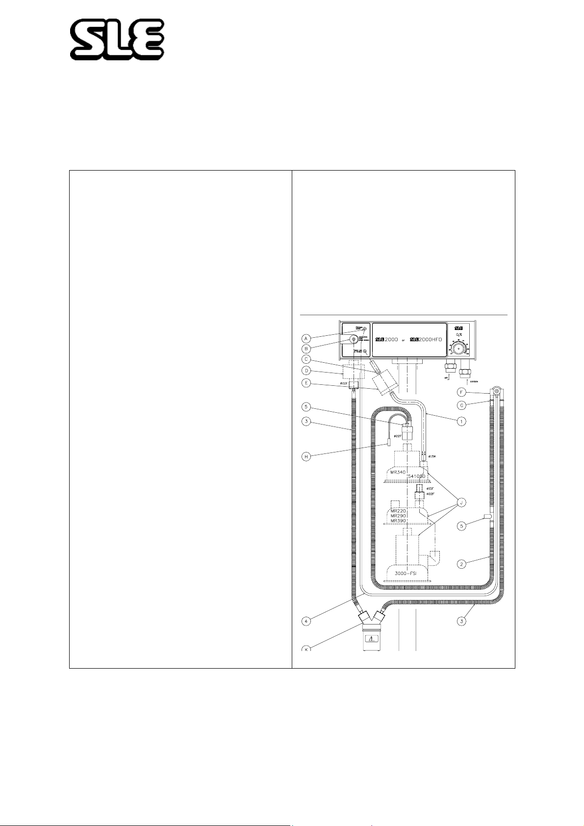
SINGLE USE PATIENT CIRCUIT(SLE Part Nº N2188)
This non-sterile circuit is for single patient use only. It is designed to be used
with an SLE2000 or SLE2000HFO Infant Ventilator in combination with a Servo
controlled humidifier - typically SLE3000, Fisher and Paykel or equivalent.
DIRECTIONS FOR USE
It is recommended that a high quality bacteria filter (SLE part
No. N2029) is fitted at the fresh gas connection to the
humidifier inlet, however the circuit may be used without.
Connect the patient circuit as shown in the diagram and
described below. Drain water trap regularly by removing the
bottom cup.
(Circuit pressure is not lost when cup is removed).
1.HUMIDIFIER SUPPLY LINE
If a bacteria filter is being used, fit the very short piece of
transparent tube to the ventilator outlet marked “Fresh Gas to
Patient”. Fit the bacteria filter into this tube. Take the loose
length of blue pipe and connect the small end of this to the
bacteria filter and the larger end to the humidifier inlet. If a
bacteria filter is not being used, connect the loose length of
blue tube directly between the “Fresh Gas to Patient”
ventilator outlet and the humidifier inlet.
2. INSPIRATORY SUPPLY LINE
Take the main patient circuit and fit the blue tube with the
large connector to the humidifier outlet. Plug the electrical
connector into the humidifier heated wire supply.
3. EXPIRATORY SUPPLY LINE
Take the clear tube with the large connector and fit to the
exhalation port of the ventilator. Position water trap in an
upright position at the lowest point in the circuit limb.
CAUTIONS
• Make sure that all connections are made properly and
are tight before use.
• For circuit heating, follow the directions provided with the
• humidifier
• Do not use in applications where gas temperature at
outlet of humidifier exceeds 55oC.
• Do not cover the patient circuit with anything which may
cause the tube to overheat.
• Avoid resting the patient circuit against patient skin
• Keep water trap upright with cup at bottom. Make sure
the drain cup is secure.
4. PROXIMAL AIRWAY PRESSURE LINE
Connect the small diameter clear tube from the patient circuit
to the proximal airway port on the ventilator.
5. TEMPERATURE MONITORING
Two ports are provided for dual temperature probes, one in
the connector on the humidifier outlet (next to the heated wire
inlet) and a second port in the blue tube close to the ET
connector.
A Proximal Airway
B Exhalation Port (from patient)
C Short Tube
D Single Use Bacteria Filter SLE Part No. N2587 or N2187
E Autoclavable Bacteria Filter SLE Part No. N2029
F ET Manifold
G Red Restrictor
H To Heater Wire Adaptor
J Humidification Chamber
K Water Trap
Page 48 of 70
Page 49
Technical Information
13. Filter Systems
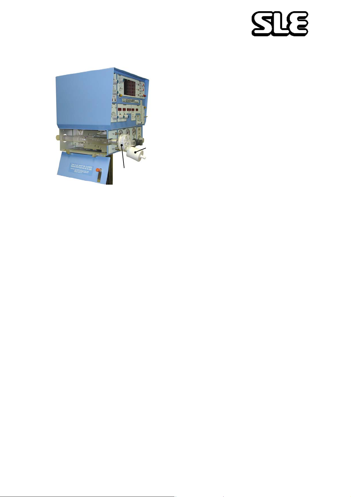
It is recommended that bacteria filters are
fitted in the fresh gas supply and on the
patient side of the exhalation block.
The filters reduce the possibility of infection
to the patient and contamination of the
ventilator from secretions or fluids in the
breathing circuits that could accidentally
Bacteria
Filter
N2029
Bacteria Filter
N2587
The SLE2000 HFO can be used without bacterial filters in place, but the user must
take extra care in not allowing secretions or fluids to enter the ventilators gas ports.
enter the ventilators gas ports.
It is recommended that a silencer be fitted
on the exhaust side of the exhalation block,
this helps to reduce the noise level of the
system.
13.1 Bacterial filter, SLE Part Nº:N2029 (Autoclavable)
This autoclavable bacterial filter is fitted into the humidifier supply line and has to be
fitted in accordance with the indicator arrow embossed on the surface of the filter.
Do not immerse the filter in any liquid.
Autoclave with pure dry saturated steam at:
134ºC (277ºF) (Allowable variation of temperature of +3ºC) at 220kPa (32psi) with a
minimum holding time of 3 minutes
or
121ºC (248ºF) (Allowable variation of temperature of +3ºC) at 96kPa (14.1psi) with a
minimum holding time of 15 minutes.
The filter can be autocalved a maximum of 25 times within its anticipated service life
of 12 months. For other makes of
bacterial filter please refer to manufacturers
instructions.
13.2 Bacterial filter, SLE Part Nº:N2587 (Single use)
This single use bacterial filter is fitted onto the exhalation block outlet. This filter
should be disposed of in accordance with local hospital authority guidelines. A new
filter should be used for every new patient.
13.2.1 Precautions when using bacterial filter N2587
The user should be aware that any occlusion of the filter increases the resistance to
airflow , resulting in increased or erratic airway pressures. Airway pressures should be
monitored during use and the filter changed if found to be contaminated in any way.
When using humidification the filter should be checked regularly for signs of water
build up which could cause occlusion.
Page 49 of 70
Page 50

Technical Information
14. Cleaning, Disinfection and Sterilization
All cleaning, disinfection and sterilizing should be carried out under the direction of the
appropriate hospital authority.
DO NOT allow moisture to enter the electronic module or its electrical sockets.
Electronic malfunction may result.
DO NOT steam autoclave the SLE 2000 HFO or otherwise subject it to temperatures
above 62°C.
DO NOT immerse any part of the SLE 2000 HFO in any liquid, with the exception of
the expiratory exhalation block (SLE part No N0635).
14.1 Preparation of a new ventilator
Remove all transit packaging. Inspect the fresh gas port and proximal airway port for
any packing material. (Retain packaging for future use as the ventilator must be
returned in its original box).
Remove the protective film from the LCD screen.
Clean, disinfect and sterilize in accordance with the instructions in section 14.2 .
Remove the inlet air and O2 gas port caps. (Retain for future use).
14.2 Cleaning and disinfection of an in-service ventilator
The table 1 outlines the areas of the ventilator which can be uniquely cleaned,
disinfected and sterilized.
Before cleaning or disinfecting the exterior of the ventilator the following tasks should
be performed:
• The mains cable should be disconnected from the mains supply.
• Remove the patient circuit and bacterial filters. Discard any single use items
as per appropriate hospital authority guidelines. Reusable items should be
processed as per appropriate hospital authority guidelines and the
manufacturers instructions.
• Disconnect the gas supplies from the wall outlets.
• Disconnect the Oxygen and Air hoses from the ventilator and cap the inlet
ports.
Page 50 of 70
Page 51
Technical Information
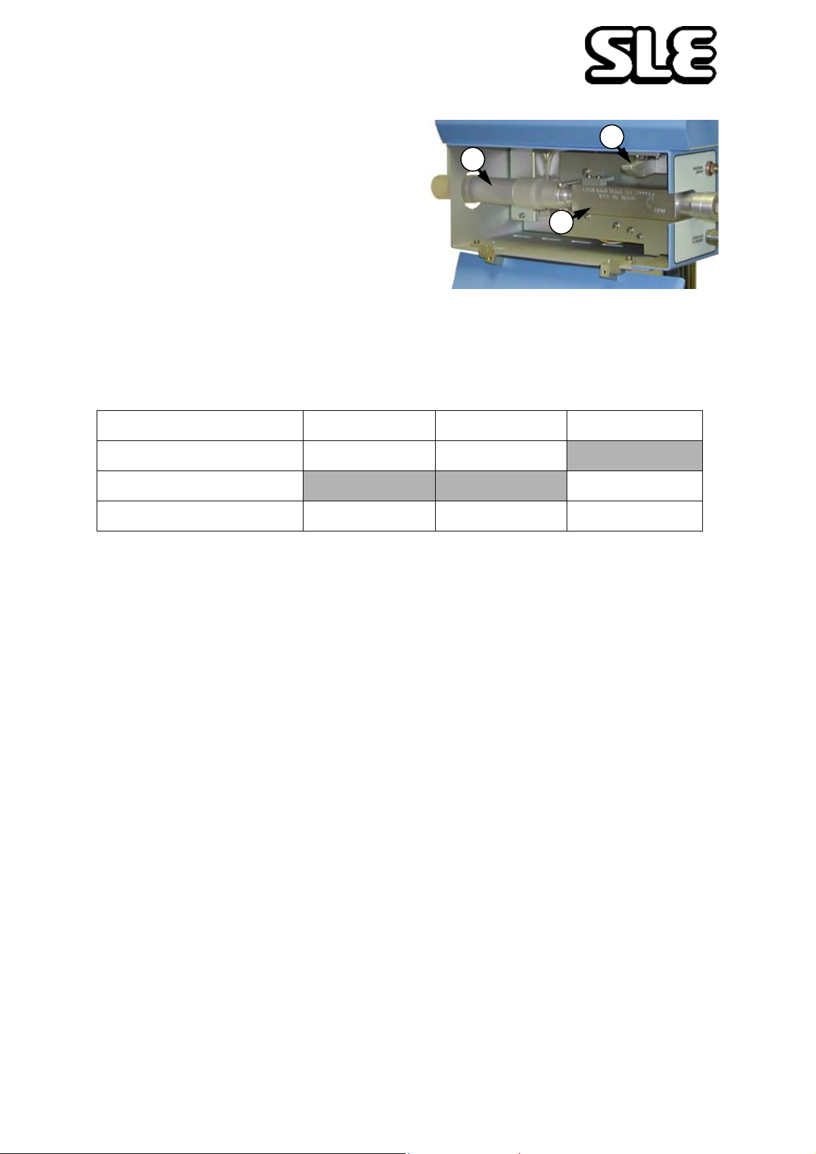
• Lift up lever (A) on side of ventilator
and lower side flap.
B
• Remove the silencer (B) by pulling
it through the hole at the rear.
• Remove the exhalation block (C)
by firstly taking hold of the block
and then pulling it out towards you
without the need for undue force.
Refitting the silencer and exhalation block is the reversal of removal. Do not force the
exhalation block into place.
14.2.1 Cleaning, Disinfection & Sterilization chart
Item Clean Disinfect Sterilize
Ventilator Yes Yes
Silencer Yes
Exhalation block Yes Yes Yes
C
A
Table 1
Warnings (General): Do not insert any object (such as a needle) in to the gas
ports. This action will result in damage to the port. If the user believes there is a
foreign object in a gas port, please refer the ventilator to qualified service
personnel for inspection and repair.
Note: The silencer should be autoclaved only. If the silencer is found to have
visual contamination internally, discard and replace with a new silencer.
14.3 Cleaning method
Note: Cleaning is an essential prerequisite to disinfection and sterilization.
Ventilator. For cleaning use three clean, disposable, absorbent, non-shedding cloths.
Wipe clean with the first cloth using a hand hot water/mild general purpose detergent
solution (as prescribed by the appropriate hospital authority). Do not overload the
cloth with liquid. Remove the water/mild general purpose detergent solution with the
second cloth using water only. Do not overload the cloth with liquid. Wipe dry with the
remaining cloth. Care should be taken to ensure that the ventilator gas jets in the ports
are not blocked by any debris.
Exhalation block. The exhalation block can be immersed and agitated in the
detergent solution. Do not insert any objects into the exhalation block. Rinse the
exhalation block in clean water, it must be allowed to dry thoroughly before
sterilization.
Page 51 of 70
Page 52

Technical Information
Warning: Ensure that the detergent solution or water does not enter the unit or
the exhalation block gas ports on the side of the machine.
14.4 Disinfection method
Note: Alcohols such as 70% isopropanol have a good activity against bacteria
and viruses. They should only be used after all visible surface dirt has been
removed from the area to be disinfected.
Ventilator. For disinfection use two clean, disposable, absorbent, non-shedding
cloths. Wipe clean with the first cloth using Alcohol (70% isopropanol). Wipe dry with
the remaining cloth.
Exhalation block. The exhalation block can be immersed in Alcohol (70%
isopropanol). The exhalation block must be allowed to dry thoroughly before
sterilization.
14.5 Sterilization method
The silencer SLE part Nº N2186 and exhalation block SLE part Nº N0635 must be
sterilized between use on patients. The ventilator cannot be sterilized.
The exhalation block must be cleaned as an essential prerequisite to sterilization.
Autoclave with pure dry saturated steam at:
134ºC (277ºF) (Allowable variation of temperature of +3ºC) at 220kPa (32psi) with a
minimum holding time of 3 minutes
or
121ºC (248ºF) (Allowable variation of temperature of +3ºC) at 96kPa (14.1psi) with a
minimum holding time of 15 minutes.
There is no limit on number of autoclave cycles for the exhalation block.
The silencer can be autoclaved up to 20 times. The body of the silencer should be
marked after each autoclave cycle with a high temperature, water proof, permanent
maker to indicate number of sterilization cycles completed.
Page 52 of 70
Page 53

Technical Information
15. Service and Maintenance Programmes
Service or calibration of this ventilator should only be carried out by an SLE
trained hospital engineer or an SLE service engineer.
15.1 Maintenance
6 Month Preventative Maintenance
Preventative maintenance should be performed at 6 monthly intervals. This
maintenance is intended to be carried out in the hospital.
A service manual is available for use by qualified engineers who have been
trained by SLE on this product. Contact SLE or your distributor for further
information.
15.2 Overhaul at 10,000 and 20,000 hours
10,000 Hrs. (24 Months) & 20,000 Hrs. (48 Months)
These overhauls must be performed by a SLE trained hospital engineer or a SLE
service engineer.
A overhaul and repair manual is available for use by qualified engineers who
have been trained by SLE on this product. Contact SLE or your distributor for
further information.
Page 53 of 70
Page 54

Technical Information
16. User Operational Checks
1. Functional test as described in section 6. on page 18, should be carried out every
time the patient circuit is changed.
2. Fan Filters Change all three fan filters every 2000 hours use, or every 6 months.
The filters are accessed by pulling the fan covers off.
• Two on the back panel and one on the side panel
• SLE part no M0701/04
3. Check the running time meter on the rear of the ventilator to see if preventative
maintenance or overhaul is due. Arrange if necessary.
4. It is the users responsibility to ensure that the ventilator is maintained in accordance
with the service programme;
Preventative maintenance:- 6 monthly
Overhaul:- 10,000 hours or 24 monthly.
Page 54 of 70
Page 55

Technical Information
17. SLE 2000 HFO Trouble Shooting Chart
Symptom Possible Cause Remedy
Leak Alarm - audible
& visual
Block Alarm audible & visual
Blender Alarm audible when both
gases connected.
Incorrect circuit fitted.
Damaged circuit fitted.
Humidifier chamber.
High alarm condition.
Fresh gas supply has
decreased.
Leak alarm drift
Fresh gas filter blocked.
Fresh gas restrictor blocked.
Alarm shuttle sticking.
Replace with correct circuit
P/No. N2188 or variant.
Replace with new circuit.
Replace chamber.
High alarm LED illuminated
Reset Insp. pressure and/or
adjust High alarm parameter
Consult Service Manual.
Consult Service Manual.
Replace filter.
Replace circuit.
Remove both gases from supply
and re-connect O
does not work, disconnect and
then connect the Air first.
Consult SLE trained Engineer if
alarm persists.
first. If this
2
High Alarm - audible
& visual
Cycle Fail Alarm audible & visual.
Either Air or O2 gas has failed
Air/O2 differential pressure
exceeded.
Compressor
Incorrect alarm setting. Reset alarm parameter or
Incorrect alarm setting.
Proximal Airway line
disconnected.
Solenoid failure.
Repair gas supply
Check that the difference in
pressure between the two
gasses is less then 30 PSI.
Check that performance gauge
is within limits. Consult
manufacture’s User Manual.
pressure setting.
Adjust to centre of waveform.
Reconnect tubing.
Consult Service Manual or SLE
trained Engineer.
Page 55 of 70
Page 56

Technical Information
Symptom Possible Cause Remedy
HFO Fail Alarmaudible & visual.
Fan Fail Alarm audible & visual.
System Fail audible & visual.
CPAP
Unable to set
desired pressure.
Component failure Refer to qualified SLE trained
Engineer
Component failure As above.
Component failure As above.
Faulty patient circuit.
Incorrectly assembled patient
circuit.
Exhalation block - located
incorrectly.
Regulator cap is in LOCKED
position.
Jammed regulator.
CPAP nozzle blocked.
Replace circuit.
Reassemble as per drawing
supplied with circuit.
Relocate the block assembly.
Pull regulator cap out to release
from locked status.
Consult SLE trained Engineer.
Consult SLE trained Engineer.
PEAK INSP.
PRESSURE
Unable to set
desired pressure.
Faulty patient circuit.
Incorrectly assembled patient
circuit.
Exhalation block - located
incorrectly.
Regulator cap is in LOCKED
position.
Jammed regulator.
Insp. nozzle blocked.
High alarm condition.
Water in proximal airway
pressure tubing
Replace circuit.
Reassemble as per drawing
supplied with circuit.
Relocate the block assembly.
Pull regulator cap out to release
from locked status.
Consult Service Manual.
Consult SLE trained Engineer.
Consult SLE trained Engineer.
Reset alarm setting.
Drain tube
Page 56 of 70
Page 57

Technical Information
Symptom Possible Cause Remedy
OSCILLATION
PRESSURE
Unable to set
desired pressure.
OSCILLATION
No Oscillation when
expected
Faulty patient circuit.
Incorrectly assembled patient
circuit.
Exhalation block - located
incorrectly.
Regulator cap is in LOCKED
position.
Jammed regulator.
Jet nozzle blocked.
High alarm condition.
HFO Mode Switch off.
HFO Mode Switch in INSP.
Mode while Main Mode Switch is
in CPAP Mode.
Replace circuit.
Reassemble as per drawing
supplied with circuit.
Relocate the block assembly.
Pull regulator cap out to release
from locked status.
Consult SLE trained Engineer.
Consult SLE trained Engineer.
Reset alarm setting.
Turn to EXP. or CONT.
Turn to Mode Switch to correct
Mode of ventilation.
NO OSCILLATION
WITH ALARMS.
HFO and CYCLE fail
alarms
CYCLE fail alarm
HELP message.
Displayed in I:E
window
SOL message
displayed in BPM
window.
Waveform has a
slow rise time.
Motor fail.
Solenoid failure.
System failure Consult SLE trained Engineer.
System failure Consult SLE trained Engineer.
Water in proximal airway line. Replace patient circuit.
Consult SLE trained Engineer.
Consult SLE trained Engineer.
Consult SLE trained Engineer.
Page 57 of 70
Page 58

Technical Information
18. Service Programmes
Service or calibration of this ventilator should only be carried out by an SLE
trained hospital engineer or an SLE service engineer.
To assist in checking operational use and service periods, the ventilator is fitted with a
time elapsed meter. Times should be noted when any service or major component
replacement is carried out on individual units.
6 MONTHLY PREVENTATIVE MAINTENANCE
Preventative maintenance should be performed at 6 monthly intervals. This
maintenance is intended to be carried out in the hospital. Preventative Maintenance
will include:-
• Visual inspection of and cleaning of all exterior surfaces, controls, attachments and
accessories.
• Removing the covers and cleaning all dust from interior of the unit.
• Visual inspection of all tubing, electrical wiring, connectors, crimps, screws, nuts,
hardware and checking the general condition of all other internal components and
assemblies.
• Inspection of the mains failure battery holder for corrosion and replacement of the
battery.
• Pneumatic and Electronic testing and where necessary calibration of ventilator.
• A maintenance agreement is available. Contact your distributor for further details.
Page 58 of 70
Page 59

Technical Information
10,000 Hrs (24 MONTHLY) OVERHAUL
Overhaul should be carried out at a maximum of 10,000 hours operation or every two
years of service. This overhaul must be performed by an SLE trained hospital
engineer or an SLE service engineer.
In addition to the checks and items performed during the preventative maintenance,
an overhaul will include replacement of:-
• Oxygen monitor cell
• Oxygen blender
• Main solenoid SV1
• Oscillator, Inspiratory and CPAP regulators
Checking operation and general condition and replacing where necessary the
following components:
• Solenoid valves SV2, SV3, SV4 and SV5
• Tubing and connectors.
• Battery holder.
• Alarm sounders.
• Mode, wave shape, frequency range and pressure range switches.
• Pressure relief valves.
• Oscillator motor & Tacho system.
• Rotating jet
A service manual including circuit diagrams descriptions of operations, parts
lists etc., is available for use by qualified engineers who have been trained by
SLE on this product. Contact your distributor for further information.
• SLE can offer an exchange service for the complete pneumatic module.
Page 59 of 70
Page 60

Technical Information
19. Pressure Unit Conversion Constants
PSI
a
k Pascal bar
PSI 1.000 6.8947
k Pascal 0.14504 1.000
6.8947 x 10
10.000 x 10
cmH2O
-2
70.308 51.715
-3
10.1973 7.5006
b
bar 14.5 100 1.000 1019.73 750.06
cmH2O 1.42237 x
-2
10
mmHg 1.9337 x
-2
10
0.09806
0.13332
9.806 x 10
1.3332 x 10
-4
1.000 0.7355
-3
1.3595 1.000
For example: To convert PSI to cmH2O multiply by 70.308
Notes:
a. PSI - pound per square inch
b. at 4 oC
mmHg
c
c. at 0 oC
Page 60 of 70
Page 61

Technical Information
20. Technical Specification
20.1 Conventional Ventilation
Modes: CPAP,CMV,PTV,SIMV
BPM Range: 1-150 breaths per minute (1BPM STEPS)
Inspiratory Time: 0.1-3.0 seconds (0.02 SECOND STEPS)
I:E Range : 9.9:1 - 1:9.9 calculated from BPM and
Inspiratory time settings.
CPAPPressure: 0 cmH2O to 35 cmH2O minimum.
Inspiratory Pressure: 0 cmH2O to 60 cmH2O
switched fast or slow rise waveforms.
20.2 HFO Ventilation
Modes: EXP, INSP, CONT (COMBINED), CONT
(OSCILLATION)
Frequency Range: 3-20 Hz. (1 Hz resolution.)
Differential Pressure Range: 0 - 90 cmH2O peak to peak
Mean Airway Range: 0 - 35 cmH2O.
20.3 Displays
240 × 128 pixel backlit LCD
display.
Selectable pressure range: -5 to +60 cmH2O or -60 to +60 cmH2O
Selectable timebase frame: 6,4,3,2,1,0.5 seconds, showing pressure
waveform, LOW, CYCLE FAIL, HIGH alarm
settings and HFO rate. Freeze facility.
40 Segment bargraph display: showing pressure waveform, LOW, CYCLE
FA IL, HIGH alarm settings in the range -10 to
+70 cmH2O. (± 2 cmH2O)
Seven segment LEDs: showing BPM, INSP. TIME, I:E RATIO, FIO2
and PRESSURE (max., mean or min ±1cm
H2O).
Indicator LEDs: MAX., MEAN, MIN. pressures, MUTE,
POWER, TRIGGER BACKUP.
Driving Pressure Gauges:
(Scaled for resultant airway
pressures)
CPAP/PEEP : 0-40 cmH2O
Oscillator : 0-50 cmH2O
Inspiratory : 0-60 cmH2O
Page 61 of 70
Page 62

20.4 Controls
Technical Information
Conventional ventilation mode
switch:
BPM Control (ten turn): 1 to 150 BPM
INSP. TIME Control (ten turn): 0.10 to 3.00 seconds
Pressure Display Switch: MAX., MEAN, MIN.
Pressure Display Switch LCD: -5 to +60 cmH2O or -60 to +60 cmH2O
Pressure Wave Switch: Slow or Fast rise
Manual Breath Pushbutton
Alarm Mute Pushbutton
Reset Pushbutton:
Display Freeze pushbutton: Active for 60 seconds (approximately)
Trigger Sensitivity Control: Range: 2ml / 0.5 sec max. To 10ml / 0.5 sec
OFF, ALARM TEST/CPAP, CMV, PTV, SIMV
(min exp time: 0.25 seconds)
Mute active for 60 seconds (approximately)
min. when using SLE N2188 patient circuit.
HIGH, CYCLE FAIL, LOW
pressure alarm setting controls:
Display Timebase selector switch: 6,4,3,2,1,0.5 seconds/frame
Inspiratory Pressure and CPAP
pressure controls:
HFO Mode Switch: OFF, EXP. INSP. and CONT
RATE Control: 3 to 20 Hz
HFO Pressure Control: 0 cmH2O to ±45 cmH2O
CPAP Pressure control: 0 to 35 cmH2O
Resolution : 1 cmH2O on LCD , 2 cmH2O on
bargraph
NOTE: In HFO mode, settings 4 and 6 do not
work. The display will remain set at 3.
Air/Oxygen Blender Control 21-100% ± 3%
Page 62 of 70
Page 63

Technical Information
20.5 Alarms
Audible only:
Loss of mains supply: Battery powered alarm
Loss of Air or O2 supply: Blender alarm.
Audible and Visual:
High Circuit Pressure
Cycle Fail
Low Circuit Pressure
Fresh Gas Block
Fresh Gas Leak Or Total Gas Supply
System Fail
Hfo Fail
Fan Fail.
Oxygen Concentration Alarm
20.6 Air and Oxygen Supplies
The SLE2000 HFO infant ventilator is designed to be use with medical grade
compressed air and oxygen.
20.6.1 Oxygen supply
The SLE2000 HFO requires a supply of pure oxygen between 3 to 5 bar.
20.6.2 Air supply
The SLE2000 HFO requires a supply of medical grade compressed air to ISO8573.1
Class 1.4.1 (minimum level of filtration) between 3 to 5 bar. Recommended level of
filtration is class 1.1.1.
Description of Class 1.4.1
1= particle size of 0.1 microns. 4 = Pressure dewpoint of +3ºC . 1= oil content 0.01Mg/
m3
Description of Class 1.1.1
1= particle size of 0.1 microns. 1 = Pressure dewpoint of -70ºC . 1= oil content
0.01Mg/m3
Page 63 of 70
Page 64

Technical Information
20.7 Power , Dimensions etc.
Voltage : 100-250V/ 50-60 Hz
Power : 120 VA
Fuses : 220-250V~50-60 Hz : Fuse T 1.0A
100-120V~50-60 Hz : Fuse T 2.0A
Operating Environment: Temp: 10-40°C
Humidity: 0-90% (non condensing)
Size, Ventilator only : 37 cms W × 39 cms H × 32 cms D
Height on pole: 141 cms
Weight Ventilator Only: 16 Kgs
Complies with: IEC 601-1 and 601-2-12 1988
BS 5724 Part 1 and section 2.12.1990
Patient Circuit Required: Model : N2188 Single use
Model : N2200 Re-usable
20.8 Environmental Storage Conditions
When packed for transport or storage;
Ambient Temperature : -40°C to +70°C
Relative Humidity : 10% to 90% non condensing
Atmospheric Pressure : 500hPa to 1060hPa
Page 64 of 70
Page 65
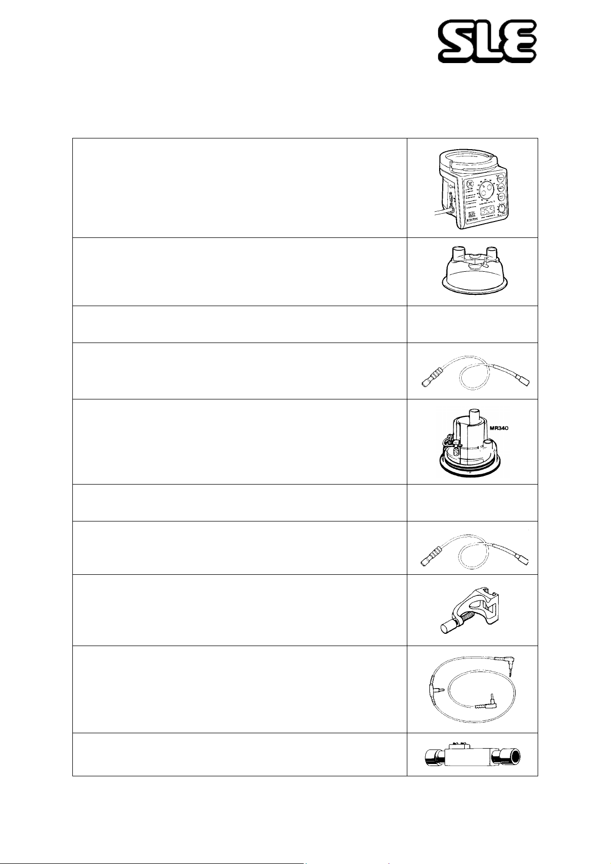
Technical Information
21. Consumables and Accessories for SLE 2000 HFO
MR700 Heater Base usable with all appropriate items
listed below
N3700/01 (230V)
N3700/02 (100V)
N3700/03 (115V)
N3220 -MR220 Single use chamber
(Box of 50) for use with above
N2188 - Standard Single use Patient Circuits for use with
above (Box of 30) Other configurations available
N3557 MR557
Heater Adapter for use with above single use patient
circuits & chambers
N3340 -MR340 Re-usable chamber
for use with above
N2391 - Re-Usable Patient Circuit for use with above
N3558 MR558 Heater Adapter for use with above
re-usable patient circuits & chambers
N3170 MR170 Pole Clamp for MR700 heater base
N3560 MR560 Dual Temperature Probe
N0635 Spare exhalation Block
Page 65 of 70
Page 66
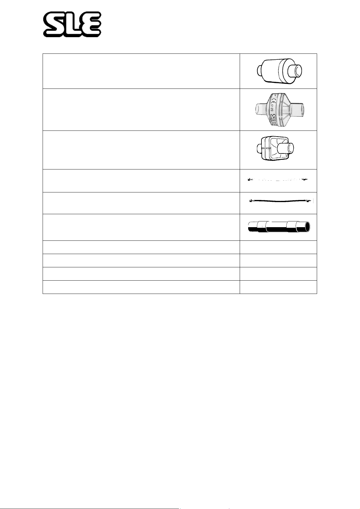
Technical Information
N2029 Bacteria filter (autoclavable)
N2587 Bacteria filter (single use)
Inlet :22mm (male) Outlet 22mm (female)
N2187 Bacteria filter (single use)
Inlet:15mm (female) or 22mm (male) Outlet: 22mm
(female) Tapered Connections
N2035 O2 (complete) 4 metres length
N2199 Air hose, 4 bar (complete) 4 metres length
N2186 Silencer (fitted to rear of exhalation block)
N2006/00 User Manual for SLE 2000 HFO
N2005/00 Service Manual for SLE 2000 HFO
N2004/01 User Manual for SLE 2000 HFO on CD-ROM
N2004 Service Manual for SLE 2000 HFO on CD-ROM
Page 66 of 70
Page 67

Technical Information
22. Ordering Information for the SLE2000 HFO
SLE 2000 HFO Z2540* (without humidifier) (3 single use Patient Circuits included
for user start up).
SLE 2000 HFO Z2541* (with humidifier) Stand mounted Ventilator, Air and
Oxygen hoses & manual.
SLE 2000 HFO Z2542* (without humidifier)
SLE 2000 HFO Z2543* (with humidifier) As above but for shelf mounting.
*State voltage required.
22.0.1 Options**
Option 1 ref. N2200 Reusable circuit start-up kit (Part No. N2200).
Option 3 ref. Z0003 Auxiliary 0-15 LPM Blended Output.
**State operation required.
22.0.2 Air Compressors
AD 3600, ref. L0035 Suitable for 1 Ventilator
AD 2000, ref. L0030 Suitable for 2 Ventilators
Page 67 of 70
Page 68

23. Technical Bulletins
Listed below are all the technical bulletins that are relevant to the SLE2000 HFO infant
ventilator.
TB 990603: Removal of hour counter from electrical chassis.
TB 000201: New versions of control software.
TB 000601: New versions of control software (V1.12).
TB 010201: New operational warnings.
TB 040401: V0226 potentiometer design change
Any of the above technical bulletins can be obtained by contacting the SLE Service
Department.
Page 68 of 70
Page 69

SLE reserves the right to make changes without prior notice in equipment, publications and prices as may be deemed necessary or desirable.
Page 69 of 70
Page 70

 Loading...