


PIX BAR PRO Quad 12
Author:
Date:
Edited:
Date:
L. Howard
02/17/2014
L. Howard
03/20/2015
User Manual
Caution: For your safety, please read this user manual carefully before initial use!
DISCLAIMER: Stage Light Company known as SLC in this document believes that the information
contained in this manual is accurate in all respects. SLC assumes no responsibility for any errors or
omissions in this documents. SLC reserves the right to revise and make changes to the content of this
document without obligation that SLC notify any person or company of such revision or changes. This
does not in any way constitute a commitment by SLC to make such changes. SLC may issue a revision of
this manual or a new edition to incorporate such changes.
1. Starting Up
What Is Included
1 x PIX BAR PRO Quad 12 RGBW Professional LED BAR
1 x powerCON Cable
Opening the Box
Thank you for purchasing one of our quality PIX BAR PRO fixtures. Featuring professional power and
data connectors, we hope you enjoy our top of the line product. When you open the box for the first
time be sure to unpack carefully. Check the box to ensure all of the contents are there. If anything
appears to be damaged through transit, notify the shipper immediately and keep the packing material for
inspection. You generally have 7 days to do so. If for any reason, the fixture needs to be returned,
please save the packing material as it is important that it be returned in the original factory box.
Contacting Us
If you need to contact us for any reason, please do not hesitate!
For a fast response please contact us via e-mail at contact@stagelightcompany.com.
Safety Instructions
DO NOT open this device, there are no user-serviceable parts inside
DO NOT look at the light source when the device is on
CAUTION: This unit’s housing may be hot when lights are operating
DO NOT leave any flammable material within 1.5 ft of this unit while operating or connected
to power
DO NOT operate this device outdoors or in location where dust, excessive heat, water, or
humidity may affect it
DO NOT connect this device to a dimmer or rheostat
ONLY connect this device to a grounded and protected circuit using provided cable
Use a safety cable when mounting this device overhead
PIX BAR PRO Quad 12 P a g e | 1 Stage Light Company, LLC
© 2014

PIX BAR PRO Quad 12
Display
Function
DMX Address
To set DMX address
DMX Channel
To set DMX channel: CH04, CH06, Ch08, CH09, CH12, Ch16, CH24, CH48
Dimmer Curve
To set dimmer speeds: <01>, <02>, <03>, <04>
Sound Mode
To set sound active mode and the sensitivity (S 000 ~ S 100)
Static Color
To set static colors
Manual Color
To set user mode intensity of R, G, B, W separately for color mixing
Auto Program
To set built-in programs: Pr 01 ~ Pr 12 and speeds <Speed 000 ~ Speed100>
Master / Slave
To set Master/Slave modes
Static Color
Static color <R>
Red
Static color <G>
Green
Static color <B>
Blue
Static color <W>
White
Static color <GB>
Green + Blue
User Manual
2. The Fixture
Rigging
The fixture may be mounted in any safe position provided there is enough room for ventilation.
When mounting the fixture use a certified theatrical rigging clamp. When mounting overhead ensure to
use properly rated rigging.
A safety cable is ALWAYS required.
Control Board Operation
Press the MENU until one of the following displayed:
Use Up and Down button to select your desired operation, then press ENTER to confirm
DMX Addressing
After selecting the “DMX Address” and pressing ENTER, use UP and DOWN to set the desired DMX
address (001~512), press ENTER again to confirm.
DMX Modes (Eight DMX modes)
After selecting the “DMX Channel” and pressing ENTER, use UP and DOWN to set the desired DMX
mode (CH04, CH06, Ch08, CH09, CH12, Ch16, CH24, CH48), press ENTER again to confirm.
Dimmer Speed Setting
After selecting the “Dimmer Curve” and pressing ENTER, use UP and DOWN to set the desired
dimmer mode (<01>, <02>, <03>, <04>), press ENTER again to confirm.
Sound Mode
After selecting the “Sound Mode” and pressing ENTER, use UP and DOWN to set sensitive (000 ~
100), press ENTER again to confirm.
Setting Static Colors
After selecting the “COLR” and pressing ENTER, use UP and DOWN to set the desired color, press
ENTER again to confirm. “CL- -” will display.
PIX BAR PRO Quad 12 P a g e | 2 Stage Light Company, LLC
© 2014
PIX BAR PRO Quad 12
Static color <RB>
Red + Blue
Static color <RG>
Red + Green
Static color <RGB>
Red + Green + Blue
Static color <RW>
Red + White
Static color <GW>
Green + White
Static color <BW>
Blue + White
Static color <RGW>
Red + Green + White
Static color <RBW>
Red + Blue + White
Static color <GBW>
Green + Blue + White
Static color <RGBW>
Red + Green + Blue + White
PROM
PR 01
R G B W colors switching
PR 02
15 colors switching
PR 03
Color macros
PR 04
Auto Chasing 1
PR 05
Auto Chasing 2
PR 06
Auto Chasing 3
PR 07
Auto Chasing 4
PR 08
Auto Chasing 5
PR 09
Auto Chasing 6
PR 10
Auto Chasing 7
PR 11
Auto Chasing 8 (Loop PR 04 ~ PR 10)
PR 12
Auto Chasing 9
User Manual
Manual Color Mode
This mode allows the user to set intensity of R, G, B, W separately to get endless color mixing from the
control board without a DMX controller present.
After selecting the “MANUAL COLOR” and pressing ENTER, use UP and DOWN to select “R / G / B /
W” for color intensity or “S” for strobe. Use UP and DOWN to set the color intensity values (0~255)
or strobe speed values (0~100), then press ENTER to confirm.
Automatic Mode
After selecting the “Auto Program” and pressing ENTER, use UP and DOWN to select the built-in
programs (PR 01 ~ PR 012) then press ENTER to confirm. Use UP and DOWN to set the operating
speed of the program (000~100), then press ENTER to confirm.
Master / Slave Operation
This mode allows for multiple slave fixtures to follow a single master fixture
1. Set the master fixture to one of the standalone operating modes: Automatic, Sound, Manual, or
Static Color
2. Set the slave fixtures to SLAVE, press ENTER.
PIX BAR PRO Quad 12 P a g e | 3 Stage Light Company, LLC
© 2014

Channel
Value
Function
1 000-255
Red 0% ~ 100%
2 000-255
Green 0% ~ 100%
3
000-255
Blue 0% ~ 100%
4
000-255
White 0% ~ 100%
5
000-255
Master Dimmer 0% ~ 100%
6
000-009
No Function
010-255
Strobe (Slow ~ Fast 1-30Hz)
7
000-009
No Function
010-029
R G B W 4 Colors Switch (Auto PR01)
030-050
15 Color Switching (Auto PR02)
051-071
Color Macros (Auto PR03)
072-092
Auto Chasing 1 (Auto PR04)
093-113
Auto Chasing 2 (Auto PR05)
114-134
Auto Chasing 3 (Auto PR06)
135-155
Auto Chasing 4 (Auto PR07)
156-176
Auto Chasing 5 (Auto PR08)
177-197
Auto Chasing 6 (Auto PR09)
198-218
Auto Chasing 7 (Auto PR10)
219-239
Auto Chasing 8 (Loop PR04 ~ PR 10)
240-255
Sound Active
8
000-255
Speed of Auto Programs (Slow ~ Fast)
9
000-009
Use the dimmer of control board setting
010-069
Linear Dimmer
070-130
Non-Linear Dimmer 1
131-191
Non-Linear Dimmer 2
192-255
Non-Linear Dimmer 3
DMX Values
9 Channels Mode
PIX BAR PRO Quad 12
User Manual
PIX BAR PRO Quad 12 P a g e | 4 Stage Light Company, LLC
© 2014

Channel
Value
Function
1
000-255
Red 0% ~ 100%
2
000-255
Green 0% ~ 100%
3
000-255
Blue 0% ~ 100%
4
000-255
White 0% ~ 100%
5 000-255
Master Dimmer 0% ~ 100%
6 000-009
No Function
010-255
Strobe (Slow ~ Fast 1-30Hz)
Channel
Value
Function
1
000-255
Red 0% ~ 100%
2
000-255
Green 0% ~ 100%
3
000-255
Blue 0% ~ 100%
4
000-255
White 0% ~ 100%
Channel
Value
Function
Section
1
000-255
Red 0% ~ 100%
1
2
000-255
Green 0% ~ 100%
3
000-255
Blue 0% ~ 100%
4
000-255
White 0% ~ 100%
5
000-255
Red 0% ~ 100%
2
6
000-255
Green 0% ~ 100%
7
000-255
Blue 0% ~ 100%
8
000-255
White 0% ~ 100%
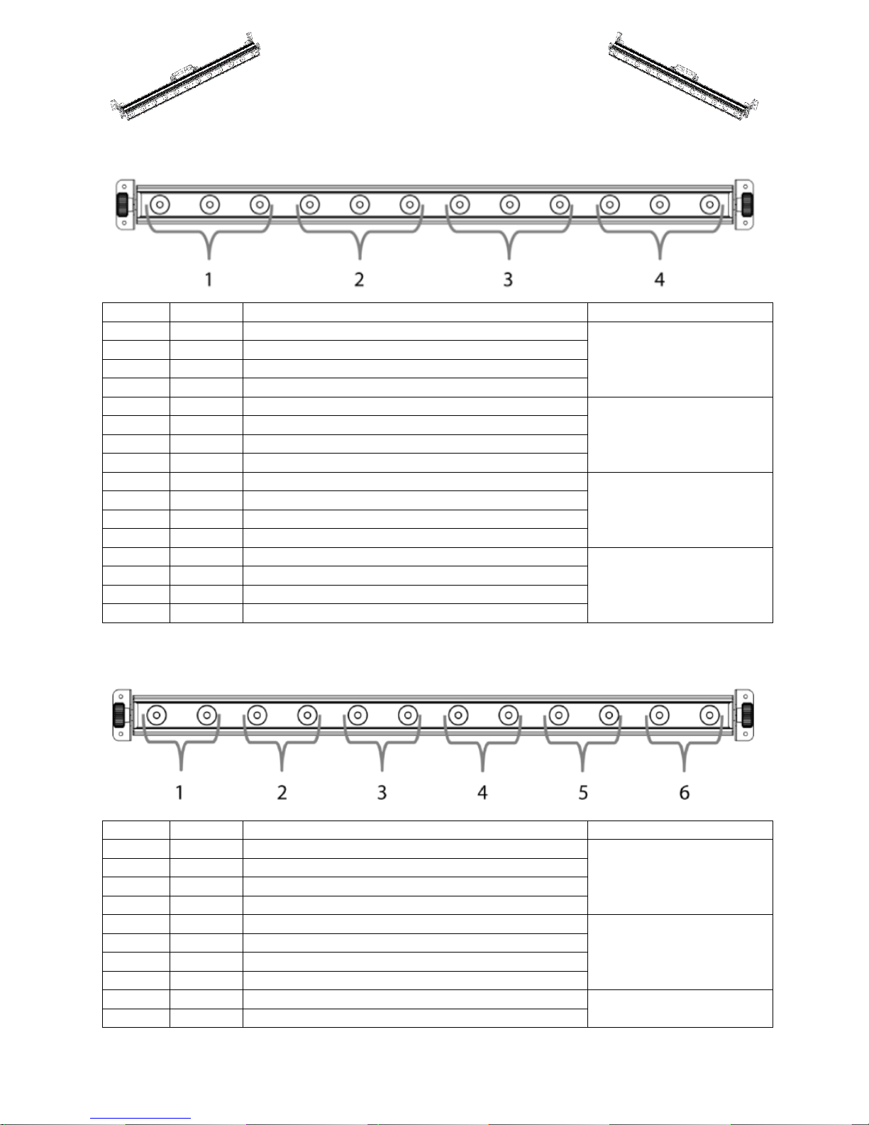
6 Channels Mode (RGBIS):
4 Channels Mode (RGBW):
PIX BAR PRO Quad 12
User Manual
8 Channels Mode:
PIX BAR PRO Quad 12 P a g e | 5 Stage Light Company, LLC
© 2014

Channel
Value
Function
Section
1
000-255
Red 0% ~ 100%
1
2
000-255
Green 0% ~ 100%
3
000-255
Blue 0% ~ 100%
4
000-255
White 0% ~ 100%
5
000-255
Red 0% ~ 100%
2
6
000-255
Green 0% ~ 100%
7
000-255
Blue 0% ~ 100%
8
000-255
White 0% ~ 100%
9
000-255
Red 0% ~ 100%
3
10
000-255
Green 0% ~ 100%
11
000-255
Blue 0% ~ 100%
12
000-255
White 0% ~ 100%
12 Channels Mode:
PIX BAR PRO Quad 12
User Manual
PIX BAR PRO Quad 12 P a g e | 6 Stage Light Company, LLC
© 2014
Channel
Value
Function
Section
1
000-255
Red 0% ~ 100%
1
2
000-255
Green 0% ~ 100%
3
000-255
Blue 0% ~ 100%
4
000-255
White 0% ~ 100%
5
000-255
Red 0% ~ 100%
2
6
000-255
Green 0% ~ 100%
7
000-255
Blue 0% ~ 100%
8
000-255
White 0% ~ 100%
9
000-255
Red 0% ~ 100%
3
10
000-255
Green 0% ~ 100%
11
000-255
Blue 0% ~ 100%
12
000-255
White 0% ~ 100%
13
000-255
Red 0% ~ 100%
4
14
000-255
Green 0% ~ 100%
15
000-255
Blue 0% ~ 100%
16
000-255
White 0% ~ 100%
Channel
Value
Function
Section
1
000-255
Red 0% ~ 100%
1
2
000-255
Green 0% ~ 100%
3
000-255
Blue 0% ~ 100%
4
000-255
White 0% ~ 100%
5
000-255
Red 0% ~ 100%
2
6
000-255
Green 0% ~ 100%
7
000-255
Blue 0% ~ 100%
8
000-255
White 0% ~ 100%
9
000-255
Red 0% ~ 100%
3
10
000-255
Green 0% ~ 100%
16 Channels Mode:
PIX BAR PRO Quad 12
User Manual
24 Channels Mode:
PIX BAR PRO Quad 12 P a g e | 7 Stage Light Company, LLC
© 2014

11
000-255
Blue 0% ~ 100%
12
000-255
White 0% ~ 100%
13
000-255
Red 0% ~ 100%
4
14
000-255
Green 0% ~ 100%
15
000-255
Blue 0% ~ 100%
16
000-255
White 0% ~ 100%
17
000-255
Red 0% ~ 100%
5
18
000-255
Green 0% ~ 100%
19
000-255
Blue 0% ~ 100%
20
000-255
White 0% ~ 100%
21
000-255
Red 0% ~ 100%
6
22
000-255
Green 0% ~ 100%
23
000-255
Blue 0% ~ 100%
24
000-255
White 0% ~ 100%
Channel
Value
Function
Section
1
000-255
Red 0% ~ 100%
1
2
000-255
Green 0% ~ 100%
3
000-255
Blue 0% ~ 100%
4
000-255
White 0% ~ 100%
5
000-255
Red 0% ~ 100%
2
6
000-255
Green 0% ~ 100%
7
000-255
Blue 0% ~ 100%
8
000-255
White 0% ~ 100%
9
000-255
Red 0% ~ 100%
3
10
000-255
Green 0% ~ 100%
11
000-255
Blue 0% ~ 100%
12
000-255
White 0% ~ 100%
13
000-255
Red 0% ~ 100%
4
14
000-255
Green 0% ~ 100%
15
000-255
Blue 0% ~ 100%
16
000-255
White 0% ~ 100%
17
000-255
Red 0% ~ 100%
5
18
000-255
Green 0% ~ 100%
19
000-255
Blue 0% ~ 100%
20
000-255
White 0% ~ 100%
21
000-255
Red 0% ~ 100%
6
48 Channels Mode:
PIX BAR PRO Quad 12
User Manual
PIX BAR PRO Quad 12 P a g e | 8 Stage Light Company, LLC
© 2014

PIX BAR PRO Quad 12
22
000-255
Green 0% ~ 100%
23
000-255
Blue 0% ~ 100%
24
000-255
White 0% ~ 100%
25
000-255
Red 0% ~ 100%
7
26
000-255
Green 0% ~ 100%
27
000-255
Blue 0% ~ 100%
28
000-255
White 0% ~ 100%
29
000-255
Red 0% ~ 100%
8
30
000-255
Green 0% ~ 100%
31
000-255
Blue 0% ~ 100%
32
000-255
White 0% ~ 100%
33
000-255
Red 0% ~ 100%
9
34
000-255
Green 0% ~ 100%
35
000-255
Blue 0% ~ 100%
36
000-255
White 0% ~ 100%
37
000-255
Red 0% ~ 100%
10
38
000-255
Green 0% ~ 100%
39
000-255
Blue 0% ~ 100%
40
000-255
White 0% ~ 100%
41
000-255
Red 0% ~ 100%
11
42
000-255
Green 0% ~ 100%
43
000-255
Blue 0% ~ 100%
44
000-255
White 0% ~ 100%
45
000-255
Red 0% ~ 100%
12
46
000-255
Green 0% ~ 100%
47
000-255
Blue 0% ~ 100%
48
000-255
White 0% ~ 100%
PIX BAR PRO Quad 12
Power Supply: 100~240 V AC, 50/60Hz~
Power Consumption: 120 W
DMX Control Channels: 8 Channel Modes (CH04, CH06, Ch08, CH09, CH12, Ch16, CH24, CH48)
Sound-Control: via Built-In Microphone
LED Type: 8 W Quad-color RGBW
Number of LEDs: 12
Beam Angle: 22˚
Dimensions (LxWxH): 1050 x 80 x 165 mm
Weight: 9lbs
Maximum Ambient Temperature: 104 ˚ F
Maximum Housing Temperature: 176 ˚ F
Min Distance from Flammable Surface: 0.5m
Min Distance to Lighted Object: 0.1m
Fuse: T 2A, 250V
User Manual
Technical Specifications
PIX BAR PRO Quad 12 P a g e | 9 Stage Light Company, LLC
© 2014

PIX BAR PRO Quad 12
Fixture 1
Fixture 2
Fixture 3
Fixture 4
Fixture 5
4ch
4ch
6ch
10ch
10ch
Addr: 001
Addr: 005
Addr:009
Addr:015
Addr:025
User Manual
3. LEDs & DMX
LED Expected Lifespan
Over time LEDs gradually decline in brightness. This is mostly caused by heat given off by clustered
LEDs. Using clustered LEDs at their full intensity is not recommended as it significantly reduces the
lifespan of the LEDs. On average, an LED can have the lifespan of 40,000 to 50,000 hours. To extend
this lifespan, ensure proper ventilation near the fixture to reduce the overall ambient temperature.
Starting Out with DMX
DMX is a data protocol most commonly used in lighting and stage equipment. DMX or DMX-512
provides control of up to 512 channels per run. A run is commonly known as a universe. Essentially
each universe provides you with 512 channels.
When connecting DMX, each fixture is daisy chained. This means that the cable comes out of the
lighting console or usb module into the first light, then the data comes out of the first light into the
second light. Please see diagram below.
Each fixture must also have an address. This address is the starting channel number. You can see in the
example above we have a range of fixtures. Some use 4 channels, some use 6 channels, etc. All of this
depends on the fixture and parameters, each fixture is different in the amount of channels it uses. The
easiest for a PRO PAR fixture is to use the 4 channel profile. You can see that before we add a new
fixture, we have to make sure we do not start the address in a channel of a previous fixture. For Fixture
1 there are 4 channels it needs to run so it occupies channels 1, 2, 3, and 4. Which means Fixture 2 will
start at channel 5 and take up 4 channels as well. Fixture 2 occupies channels 5, 6, 7, and 8. Fixture 3 will
now start at channel 9. Since it uses a profile of 6 channels, it occupies channels 9, 10, 11, 12, 13, and 14.
Try the next 2 on your own. Did you get that Fixture 5 should start at channel 25 and Fixture 6 would
start at channel 35?
Lighting Console Profiles
We are currently working with manufacturers to incorporate our products into their software. If you
do not see SLC as a manufacturer, the best place to look is under the generic section. On the PRO PAR
fixtures, set the “CHA” to 4 channels and most digital lighting consoles have a generic RGBW profile.
This is the one you want to use.
For more information please visit our site at www.stagelightcompany.com
PIX BAR PRO Quad 12 P a g e | 10 Stage Light Company, LLC
© 2014
 Loading...