

Page 1
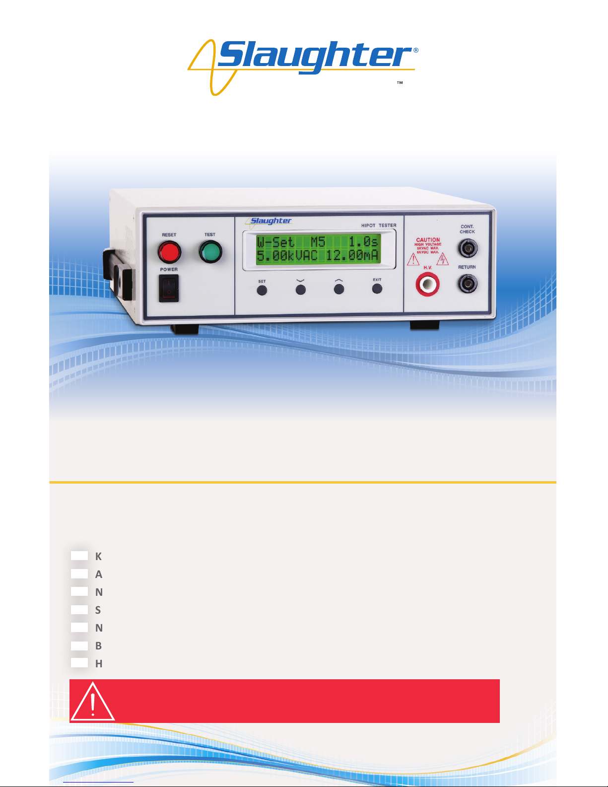
For Models: 2955, 2965 & 2975
Quick Start Guide
Safety Made Simple
2900 Series
WARNING: THIS GUIDE WAS CREATED FOR OPERATORS HAVING SOME FAMILIARITY WITH
ELECTRICAL SAFETY TESTING. AN ELECTRICAL SAFETY TESTER PRODUCES VOLTAGES AND CURRENTS THAT
CAN CAUSE HARMFUL OR FATAL ELECTRIC SHOCK. TO PREVENT ACCIDENTAL INJURY OR DEATH, THESE
SAFETY PROCEDURES MUST BE STRICTLY OBSERVED WHEN HANDLING AND USING A TEST INSTRUMENT.
SAFETY CHECKLIST
KEEP unqualied/unauthorized personnel away from the test area
ARRANGE test staons in a safe and orderly manner
NEVER touch products or connecons during a test
STOP the test rst in the event of a problem
NEVER perform a Ground Bond test on energized circuitry or equipment
BE SURE to always connect the return test lead rst
HANDLE test clips by insulaon only, never touch clips directly
Page 2
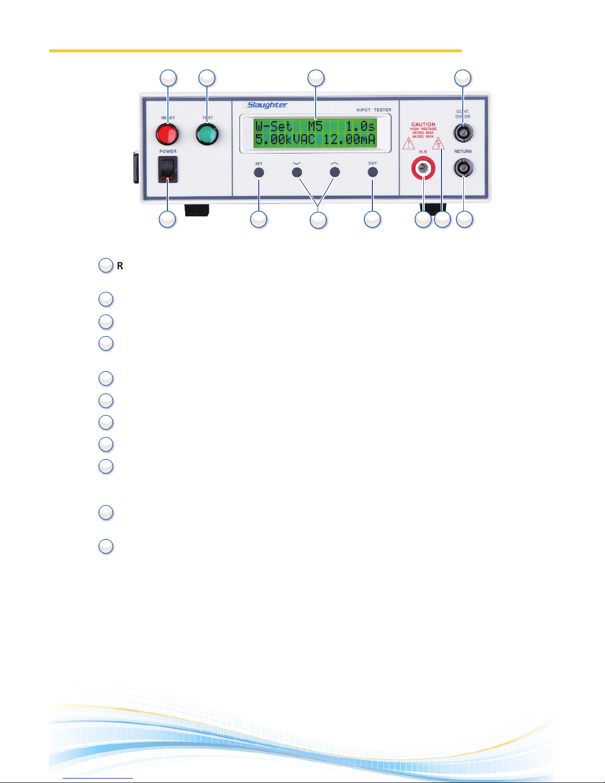
Front Panel Controls 2955/2965/2975
RESET BUTTON: Red momentary contact switch used to reset the instrument in case of a
failure. Also serves as an abort signal to stop any test in progress.
TEST BUTTON: Starts a test.
LCD DISPLAY: 16 x 2 character display.
CONTINUITY OUTPUT TERMINAL: Connector used to aach the return test lead, adapter
box return lead, or test xture return lead used during Connuity tesng.
POWER SWITCH: Rocker-style switch with internaonal ON ( I ) and OFF ( O ) markings.
SET KEY: Use this key to cycle forward through the setup menus.
UP-DOWN ARROW KEYS: Use these keys to cycle through the test parameter setup.
EXIT KEY: Use this key to exit any menu.
HIGH VOLTAGE OUTPUT TERMINAL: Provides the high voltage used during a Hipot test.
Connector used to aach the high voltage test lead, adapter box high voltage lead or test
xture high voltage lead to the instrument.
HIGH VOLTAGE INDICATOR: Indicator ashes to warn the operator that the high voltage is
present at the high voltage output terminal.
RETURN TERMINAL: Provides the return current path. Connector used to aach the
return test lead, adapter box return lead or test xture return lead to the instrument.
10
11
2
3
4
5
6
7
8
9
1
(2955 Front Panel)
1.
10 11
2 3 4
5 6
7
8 9
1
Page 3
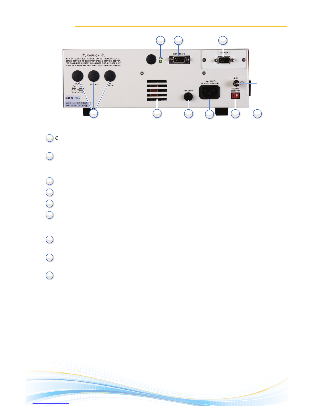
CALIBRATION KEY: Press this key while the instrument is being powered on to enter
calibraon mode.
REMOTE INPUT/OUTPUT: 9-pin D subminiature male connector for remote control of
TEST and RESET funcons as well as for monitoring PASS, FAIL, and PROCESSING output
relay signals.
BUS INTERFACE: Oponal connector for interconnecon to RS-232 bus interface.
OPTIONAL REAR OUTPUT TERMINALS: Addional output terminals.
THERMAL FAN: Used to cool the instrument.
FUSE RECEPTACLE: To change the fuse, unplug the power (mains) cord and turn the fuse
receptacle counterclockwise. The fuse compartment will be exposed. Please replace the
fuse with one of the proper rang.
INPUT POWER RECEPTACLE: Standard IEC 320 connector for connecon to a standard
NEMA style line power (mains) cord.
VOLTAGE SELECT SWITCH: Sets the line voltage conguraon of the instrument. In the le
posion it is set for 115 volt operaon, in the right posion it is set for 230 volt operaon.
CHASSIS GROUND (EARTH) TERMINAL: This safety terminal should be connected to a
good earth ground before operaon.
2
3
4
5
6
7
8
9
1
Back Panel Controls 2955/2965/2975
2.
(2955 Back Panel)
6
7
8 9
2 3
4 5
1
Page 4
115
RISK OF ELECTRICAL SHOCK. DO NOT REMOVE COVER.
REFER SERVICE TO MANUFACTURER’S SERVICE CENTER.
FOR CONTINUED PROTECTION AGAINST FIRE. REPLACE ONLY
WITH 250V FUSE OF THE SPECIFIED CURRENT RATING.
CAUTION
CAUTION
HIGH VOLTAGE
RETURN
CONT.
CHECK
H. V.
CAL.
REMOTE 1/0
RS232
F2A 250V
115~/230V~
2A MAX,. 50Hz/60Hz
GND
VOLTAGE
SELECTOR
RESET
POWER
TEST
SET
EXIT
HIPOT TESTER
CAUTION
5KVAC MAX.
6KVDC MAX.
H.V.
RETURN
CONT.
CHECK
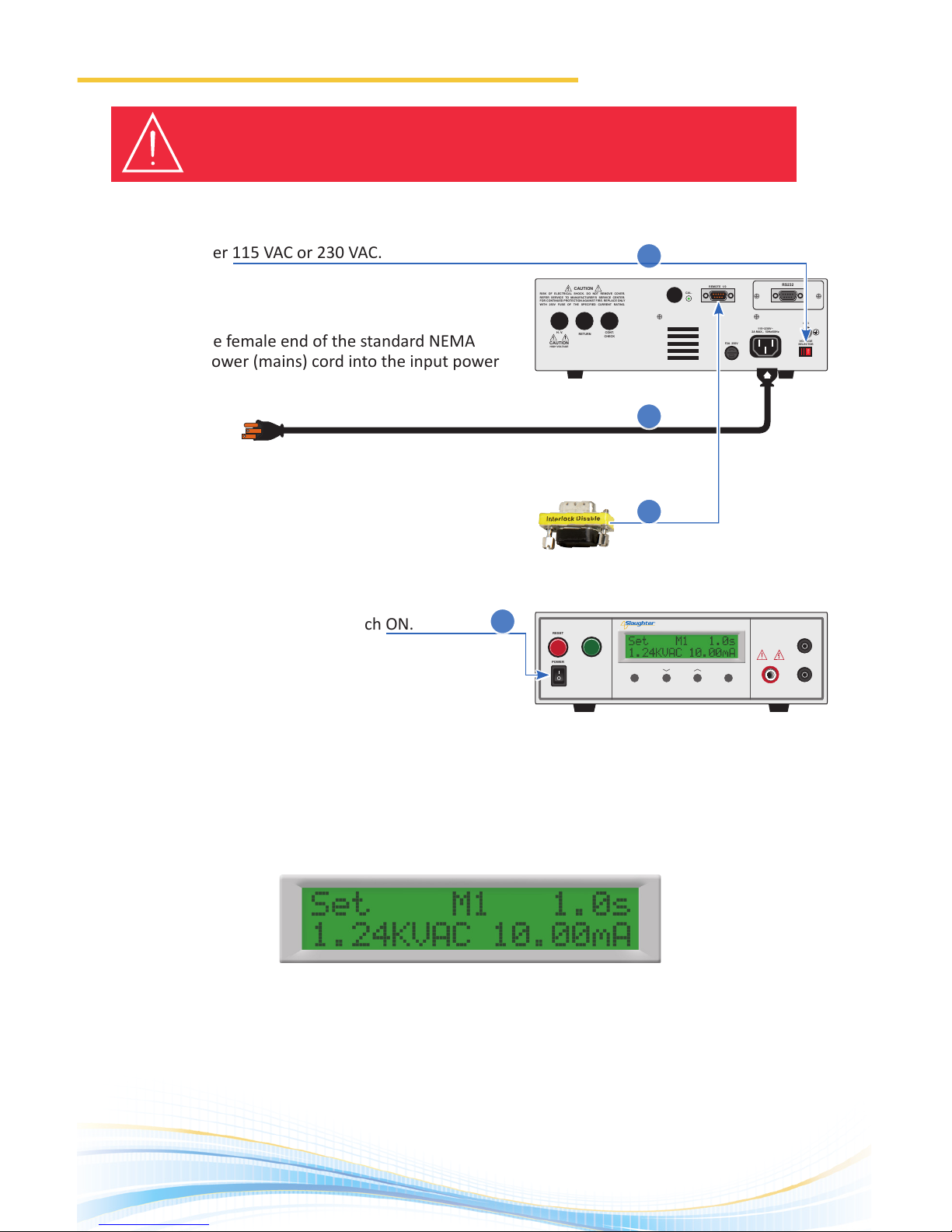
1. Adjust the line voltage select switch on the rear panel
of the instrument to the appropriate input voltage
rang, either 115 VAC or 230 VAC.
2. Connect the female end of the standard NEMA
style line power (mains) cord into the input power
receptacle on the rear panel of the instrument and
plug the male end of the cord into a grounded power
source.
3. Connect the Interlock Disable key to the Remote
Input connector on the back panel of the instrument.
This is required in order to run a test.
4. Turn the instrument power switch ON.
Upon power up, you will see the Slaughter company name, model number, and the current soware
version briey appear on the display and then you will see the default test parameters as shown.
Setting Up The Instrument
3.
WARNING: LOCATE A SUITABLE TESTING AREA WITH A THREE-PRONG, GROUNDED OUTLET. BE
SURE THAT THE THREE PRONG GROUNDED OUTLET HAS BEEN TESTED FOR PROPER WIRING. MAKE SURE YOU
READ THE SAFETY CHECKLIST OF THIS GUIDE BEFORE USING THE INSTRUMENT.
1.
2.
3.
4.
Page 5

If you wish to change the default test sengs, you will need to begin by choosing a
memory locaon rst.
1. Press the SET key from the Perform Test screen to select a memory locaon. Use the up
or down arrow keys to select memory locaons 1 – 10.
2. Press the SET key to toggle through the test parameters.
3. Use the up or down arrow keys to edit each parameter.
4. When you are nished eding the test parameters press the EXIT key to save your
sengs and return to the Perform Test Screen.
4.
Editing Test Parameters
Default test type parameters are shown below.
• Input Voltage: 115 or 230 volts AC country specic
• Lock: OFF
• Test: W - I: (2975)
AC Dielectric Withstand Test Mode
• Voltage Output: 1,240 volts AC
• High Current Trip: HI-LMT: 10 mA
• Low Current Trip: LO-LMT: 0 mA
• Ramp Timer: 0.1 second
• Dwell Timer: 1 second
• AC Output Freq.: 60Hz
• Connuity: OFF
DC Dielectric Withstand Test Mode
• Voltage Output: 1,500 volts DC
• High Current Trip: HI-LMT: 5 mA
• Low Current Trip: LO-LMT: 0 mA
• Ramp Timer: 0.1 second
• Dwell Timer: 1 second
• Connuity: OFF
Insulaon Resistance Mode (model 2975)
• Voltage Output: 1,000 volts DC
• High Resistance Trip: I - High: 0 MΩ
• Low Resistance Trip: I - Low: 1 MΩ
• Delay Timer: 2 seconds
Page 6
5.
RESET
POWER
TEST
SET
EXIT
HIPOT TESTER
CAUTION
5KVAC MAX.
6KVDC MAX.
H.V.
RETURN
CONT.
CHECK
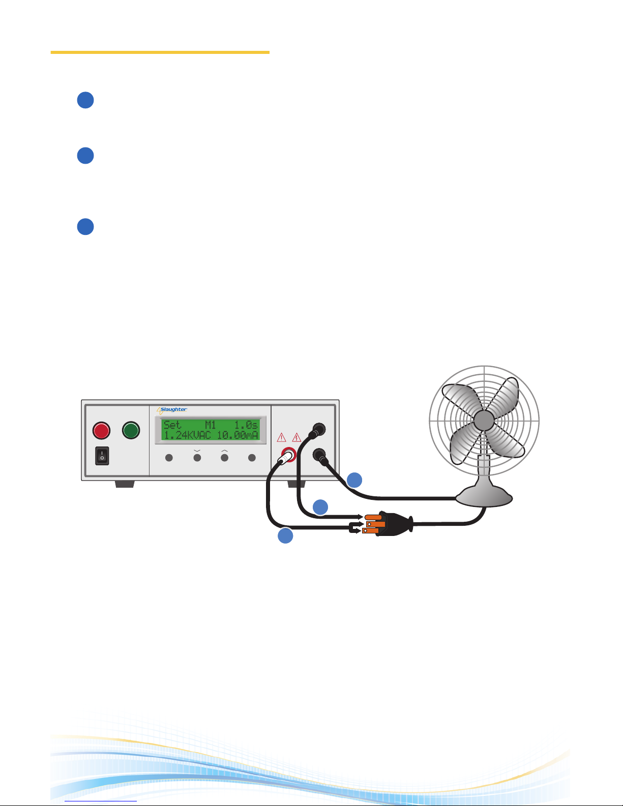
DUT Connecon
Connect the black return lead (102-069-904) to the front panel return output terminal and
connect the other end of the lead to the dead metal on the chassis of the DUT.
Connect a second black return lead (102-069-904) to the front panel connuity check
terminal and connect the other end of the lead to the third prong on the line cord coming
from the DUT .
Connect either the high voltage lead (102-055-913) or high voltage probe (102-050-913),
whichever one you are using for your applicaon, into the high voltage terminal located on
the front panel and connect the other end of the cable to both the hot and neutral pins of
the line cord.
Test Connections
1.
2.
3.
1.
2.
3.
Page 7
6.
Test Connections
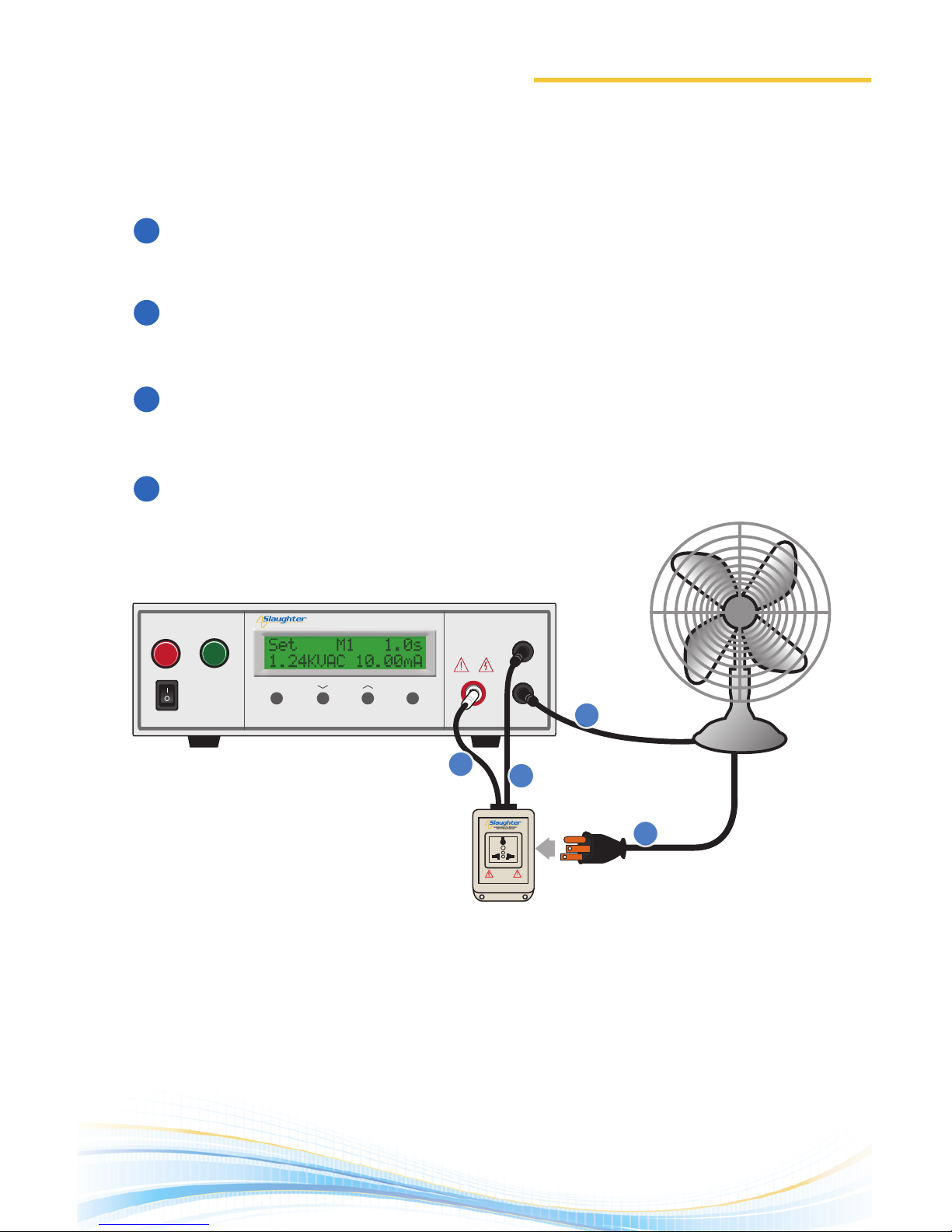
Adapter Box Connecon
The adapter box (99-10001-01) is available as an opon accessory for the 2900 series. It
provides an easy way to connect to a DUT that is terminated in a two-prong or three-prong
line cord.
Connect the black return lead (102-069-904) to the front panel return output terminal and
connect the other end of the lead to the dead metal on the chassis of the DUT.
Connect the high voltage lead from the adapter box to the front panel high voltage
terminal.
Connect the connuity lead from the adapter box to the front panel connuity check
terminal.
Plug your DUT into the adapter box.
1.
2.
3.
4.
RESET
POWER
TEST
SET
EXIT
HIPOT TESTER
CAUTION
5KVAC MAX.
6KVDC MAX.
H.V.
RETURN
CONT.
CHECK
NL
CAUTION
HIGH VOLTAGE
5KVAC MAX.
6KVDC MAX.
1.
2.
3.
4.
Page 8
www.hipot.com Toll Free +1-800-504-0055 or +1-847-932-3662
© 2013 Slaughter Company, Inc.
29XX 6/14
Safety Made Simple
Scan the QR code
to get further
support or visit
www.hipot.com/
29xx_Support/
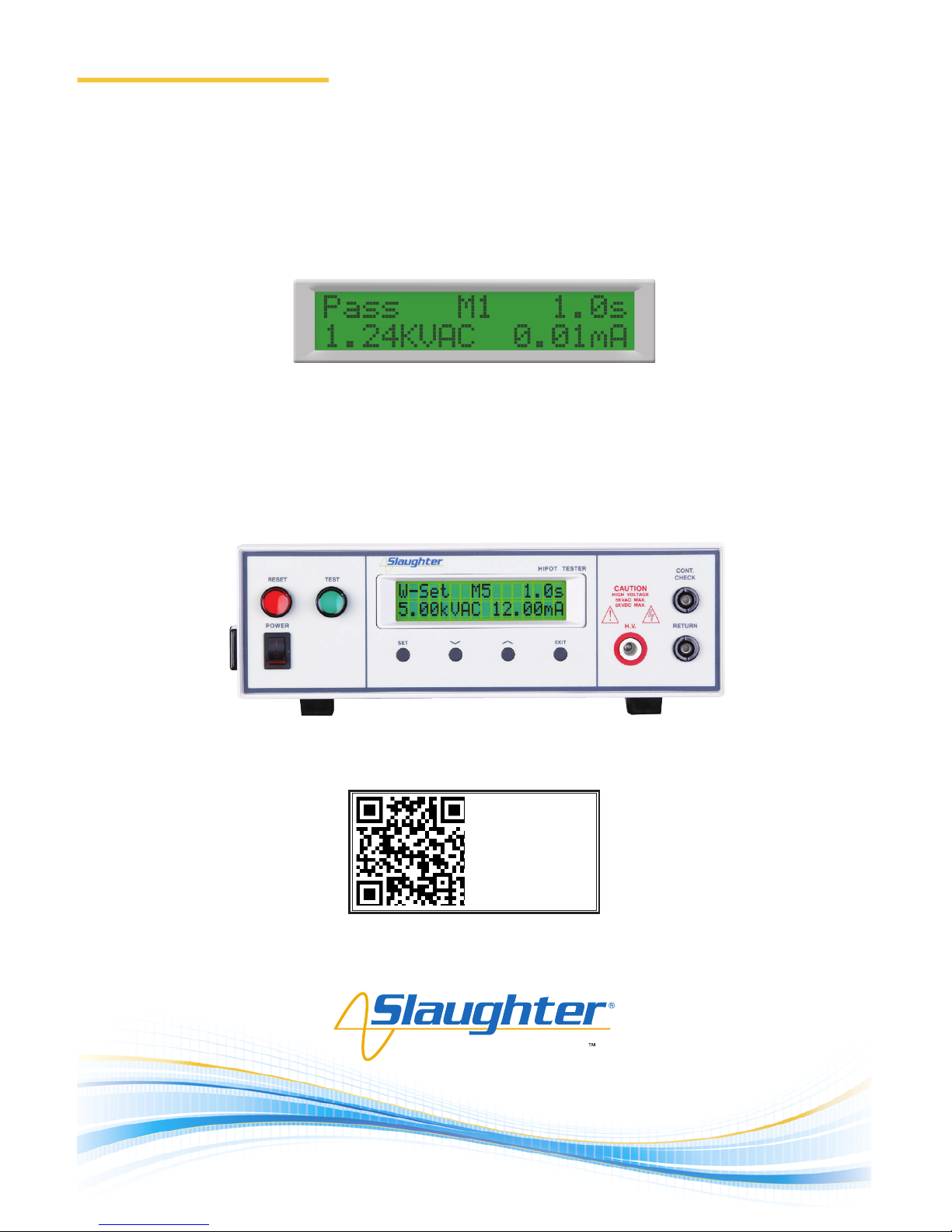
Test Results
Aer a test has been performed, the test results will be indicated on the front panel display.
PASS: If the DUT passes the test, you will hear a short audible beep and the display will
indicate the test results.
FAIL: If a failure occurs, you will hear a long audible alarm and the red ashing indicator
will light up. To stop the alarm press the red RESET buon.
 Loading...