

SLAT AES Series, AES 50 W, AES 75 W, AES 150 W, AES 200 W Operating Instructions Manual
...Page 1

NOTICE D'UTILISATION P 1
BEDIENUNGSANLEITUNG S 11
OPERATING INSTRUCTIONS P 21
GEBRUIKSHANDLEIDING P 31
MANUAL DE USUARIO
P 41
NOTICE D’UTILISATION
AES
50W à 600W
Code :
Edition : 1213
180100026Ea
- NDU :
NOT100029Ea
Page 2

Table des matières
1 Informations générales ........................................................................................... 4
1.1 Tableau des correspondances ......................................................................................................... 4
1.2 Spécifications environnementales .................................................................................................... 4
1.3 Spécifications électriques d’entrée et de sortie ................................................................................ 4
2 Installation de votre équipement............................................................................ 5
2.1 Fixation et dimensions des coffrets (dim : LxHxP mm) .................................................................... 5
2.2 Batteries ............................................................................................................................................ 6
3 Raccordement ......................................................................................................... 6
3.1 Plan de raccordement....................................................................................................................... 6
3.2 Sections maximum de raccordement ............................................................................................... 7
4 Mise en service ........................................................................................................ 7
5 Fonctionnement de l’AES ....................................................................................... 7
5.1 Alarmes ............................................................................................................................................. 7
5.2 Récapitulatif des équipements disponibles ...................................................................................... 8
6 La maintenance ....................................................................................................... 9
7 Protections fusibles ................................................................................................ 9
7.1 Versions 24V .................................................................................................................................... 9
7.2 Versions 48V .................................................................................................................................... 9
8 Procédure de dépannage ...................................................................................... 10
2
Page 3
Félicitations,
Vous venez d’acquérir une alimentation électrique sécurisée de la marque SLAT et nous vous en remercions.
Vous trouverez dans cette notice toutes les indications à suivre pour l’installation, la mise en service et la maintenance de
cet équipement.
Pour la bonne marche de l’appareil, nous vous conseillons de les suivre très attentivement.
Bonne installation.
Consignes de sécurité
Ce matériel est destiné à être raccordé au réseau 230V de distribution publique.
Afin d’éviter tout risque de choc électrique, toute INTERVENTION doit être réalisée HORS TENSION (disjoncteur bipolaire
amont ouvert)
Les travaux sous tension ne sont autorisés que pour les exploitations où la mise hors tension est impossible.
L’intervention doit être réalisée uniquement par du personnel habilité.
Normes, directives et protection de l’environnement et de la santé publique
Tous nos produits de la gamme AES suivent les directives BT et CEM (immunité et émission). Ils sont conformes aux
normes :
• EN 60950-1 (2006) + A11 (2009) + A1 (2010) + A12 (2011) + A2 (2013) (Classe TBTS)
• EN 61000-6-1(2007), EN 61000-6-2 (2005), EN 61000-6-3 (2007), EN 61000-6-4 (2007) + A1 (2011)
• EN 50130-4 (2011)
• EN 55022 (2006) + A1 (2007) classe B
• UL1950 pour les composants.
Ils sont également certifiés conformes aux normes métiers :
• EN 54-4 (1997) + A1 (2002) + A2 (2006) : Systèmes de détection et d’alarme Incendie. Partie 4 : équipement
d’alimentation électrique.
• EN 12101-10 classe A (2005): Systèmes pour le contrôle des fumées et de la chaleur. Partie 10 : équipement
d’alimentation en énergie.
• NFS 61940 (2000) : Alimentations Electriques de Sécurité.
Certains produits (24V) sont conformes aux normes :
• VdS 2541 (1996) : Energieversorgungseinrichtungen Anforderungen und Prüfmethoden.
• VdS 2344 (2012) : Procedure for the testing, approval, certification and conformity assessment of products and
systems for fire protection and security technologies.
Les numéros de DoP et les années de marquage CE sont indiquées en ANNEXE.
Les certificats peuvent être téléchargés sur notre site: http://www.slat.fr/certificatsCE.php
SLAT est certifiée ISO 14001 depuis 2008.
SLAT fabrique tous ses produits dans le respect des directives environnementales RoHS et DEEE.
SLAT assure le recyclage des produits en fin de vie à travers sa filière de recyclage.
Garantie
Notre garantie est de trois ans départ usine. Elle est strictement limitée au remboursement ou au remplacement (à notre
choix et sans indemnité d’aucune sorte) des pièces reconnues défectueuses par nos services, après retour dans nos
ateliers aux frais de l’acheteur. Nous ne saurions accepter de remplacements ou de réparations de matériels ailleurs que
dans nos ateliers. Dans le but de faire bénéficier à notre clientèle de nos dernières améliorations techniques, SLAT se
réserve le droit de procéder sur ses produits à toutes les modifications nécessaires. La batterie n’est pas incluse dans la
garantie.
3
Page 4

50W
75W
100W
150W
200W
300W
400W
600W
0.4A
0.5A
0.75A
1A
1.5A
2A 3A 4A
Tension nominale
24V 48V
1111 Informations générales
Informations générales
Informations généralesInformations générales
1.1 Tableau des correspondances
24V 2A 3A 4A 6A 8A 12A 16A 24A
48V 2A 3A 4A 6A 8A 12A
Les courants indiqués sont les courants (In) à puissance nominale de sortie
50W 75W 100W 150W 200W 300W 400W 600W
1.2 Spécifications environnementales
Température de fonctionnement :
- 5°C à + 40°C à 100 % de charge.
- 5°C à + 50°C à 75 % de charge.
- 5°C à + 50°C à 100 % de charge pour 50 à 100W
Température de stockage : -25 à +85°C.
Humidité relative : 20 à 95%.
Valeur des dégagements et potentiels calorifiques consultez notre site : www.slat.fr
Classe d’environnement : 1 (selon EN 12101-10)
1.3 Spécifications électriques d’entrée et de sortie
1.3.1 Entrée réseau
- Tension monophasée: 195V à 264V.
- fréquence: 47 à 63Hz.
- classe I.
- régimes de neutre : TT, TN, IT.
Courant primaire @ 195V
Disjoncteur à prévoir en amont : courbe D
1.3.2 Sortie
Tension de floating réglée à mi-charge et 25°C 27.2V
La version AES peut fonctionner sans courant
utilisation
Le courant de sortie In max. peut être exploité sur
une sortie seule ou réparti sur l’ensemble des
sorties.
Courant de sortie maximal spécifié qui peut être
fourni en continu. (C=capacité batterie)
Courant de sortie maximal spécifié supérieur à I
max a, qui peut être fourni pour une courte période
durant laquelle le chargement de la batterie n’est
pas exigé
Temps d’interruption 0s
4
+/-0.5%
54.4V
Imin = 0
I max a = In –C/20
I max b = In
In
+/-0.5%
Page 5
24V 48V
1.3.3 Autonomie
Pour déterminer l’autonomie de votre AES et interpréter les dates codes batteries, consultez notre site
internet : www.slat.fr
1.3.4 Capacités batterie autorisées (Ah/20h – 1.75V/élt)
50W de 7 à 38Ah de 2.1 à 12Ah
75W de 7 à 55Ah de 2.1 à 12Ah
100W de 7 à 55Ah de 2.1 à 12Ah
150W de 7 à 86Ah de 2.1 à 12Ah
200W de 7 à 110Ah de 4 à 65Ah
300W de 7 à 166Ah de 4 à 65Ah
400-600W de 7 à 225Ah de 4 à 140Ah
Vérifier que les batteries sont bien conformes aux normes en vigueur dans les pays où elles sont utilisées.
2222 Installation de votre équipement
Installation de votre équipement
Installation de votre équipementInstallation de votre équipement
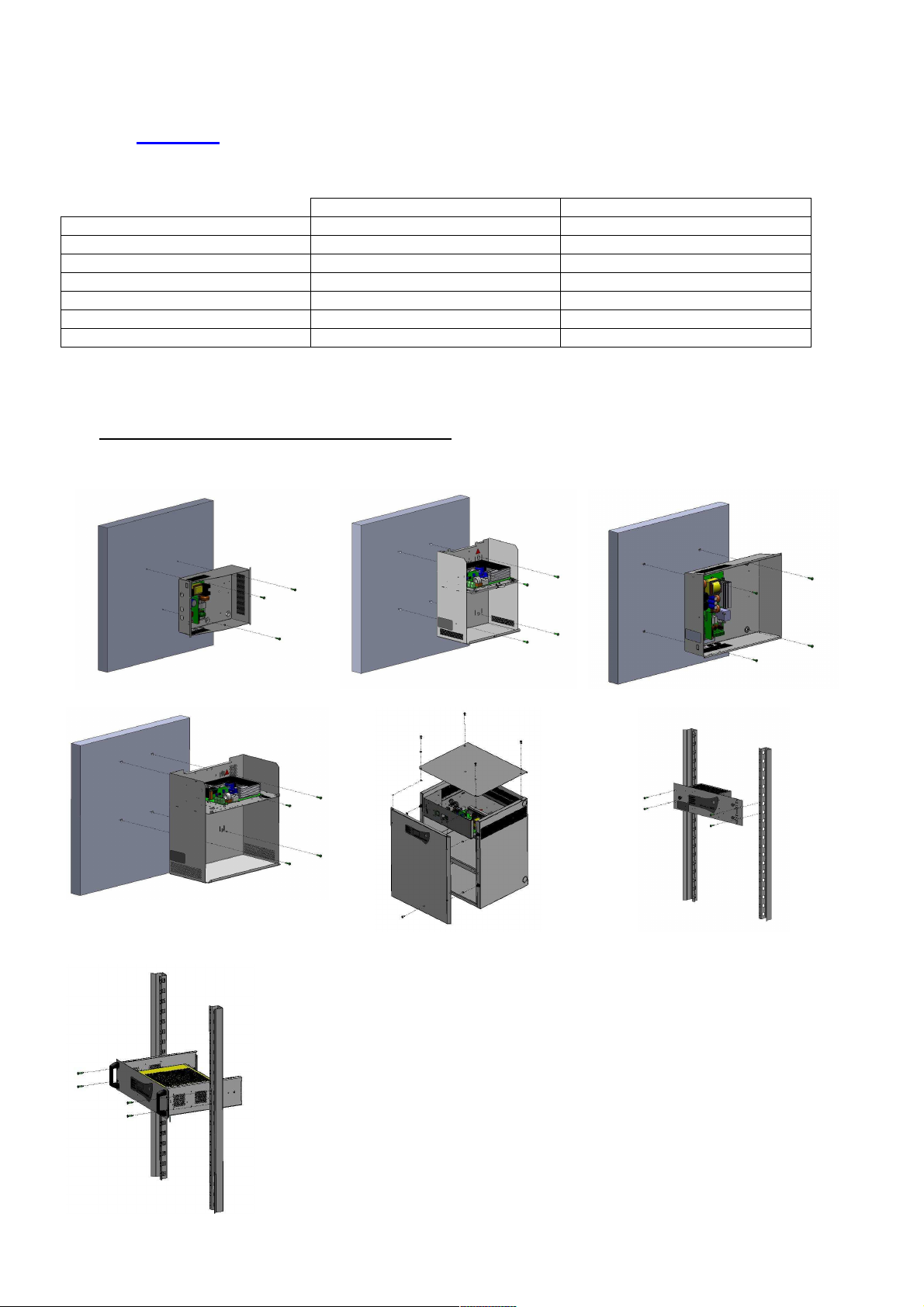
2.1 Fixation et dimensions des coffrets (dim : LxHxP mm)
C24 - Dim : 322x248x126mm - IP 30
C85 – Dim : 408x408x224mm – IP31
C38 – Dim : 289x350x189mm - IP 31 C48 – Dim : 425x345x120mm - IP30
C180 – Dim : 505x610x430mm – IP31
RackF3U – Dim : 482x133x110mm –
IP30
Rack 3U – Dim : 483x132x358mm – IP30
5
Page 6

2.2 Batteries
Vous trouverez le plan d’intégration et de câblage des batteries dans le kit fourni avec le produit (sauf rack et
F3U).
La sonde de température batterie doit être placée au plus près de la batterie.
3333 Raccordement
Raccordement
RaccordementRaccordement
3.1 Plan de raccordement
Cablage 50-75W Cablage 100-300W
1
NC
NO
NC
NO
NC
NO
NC : N o rm ally C lo s e d
NO : N o rm ally O pe n ed
2
3
4
5
6
7
8
9
Secteur
Batterie
Sortie
Câblage 400- 600W Câblage reports d’alarmes
* Le collier fourni avec tous les produits permet la fixation du câble secteur au niveau du bornier secteur.
Attention, les ouvertures prévues dans le coffret doivent être utilisées. Ne pas créer d’ouvertures
supplémentaires sous peine de dysfonctionnement de l’appareil et de non reprise sous garantie.
Tableau d’utilisation des tores
C24-C48 C38-C85 F3U Rack-C180
50-75W Aucun Aucun Aucun -
100-150W
200-300W
400-600W TORE SECTEUR +
TORE SORTIE à
monter
TORE SORTIE à
monter
TORE REPORTS +
TORE SORTIE à
monter
TORE SORTIE pré-
monté
TORE SORTIE pré-
monté
- - FILTRE/TORE
TORE SORTIE à
monter
- TORE SORTIE pré-
-
monté
SECTEUR +
TORE REPORTS +
TORE SORTIE pré-
montés
6
Page 7
3.2 Sections maximum de raccordement
50-
75W
100-150W
200-300W
400-600W
Secteur 2.5 mm² 2.5 mm² 2.5 mm² 2.5 mm²
Batteries 2.5 mm² 6 mm² 6 mm² 10 mm²
Utilisation (2 sorties) 2.5 mm² 6 mm² 6 mm² 10 mm²
Reports d’alarme (débrochable) 1.5 mm² 1.5 mm² 1.5 mm² 1.5 mm²
4444 Mise en service
Mise en service
Mise en service Mise en service
Ouvrir le fusible batterie ou pour les cartes de 50 à 150W équipées du fusible à réarmement automatique :
raccorder les fils batterie sur le bornier mais ne pas raccorder les bornes de la batterie.
Après avoir effectué les raccordements électriques (secteur, utilisations et batteries).
1. Fermer le disjoncteur secteur en amont.
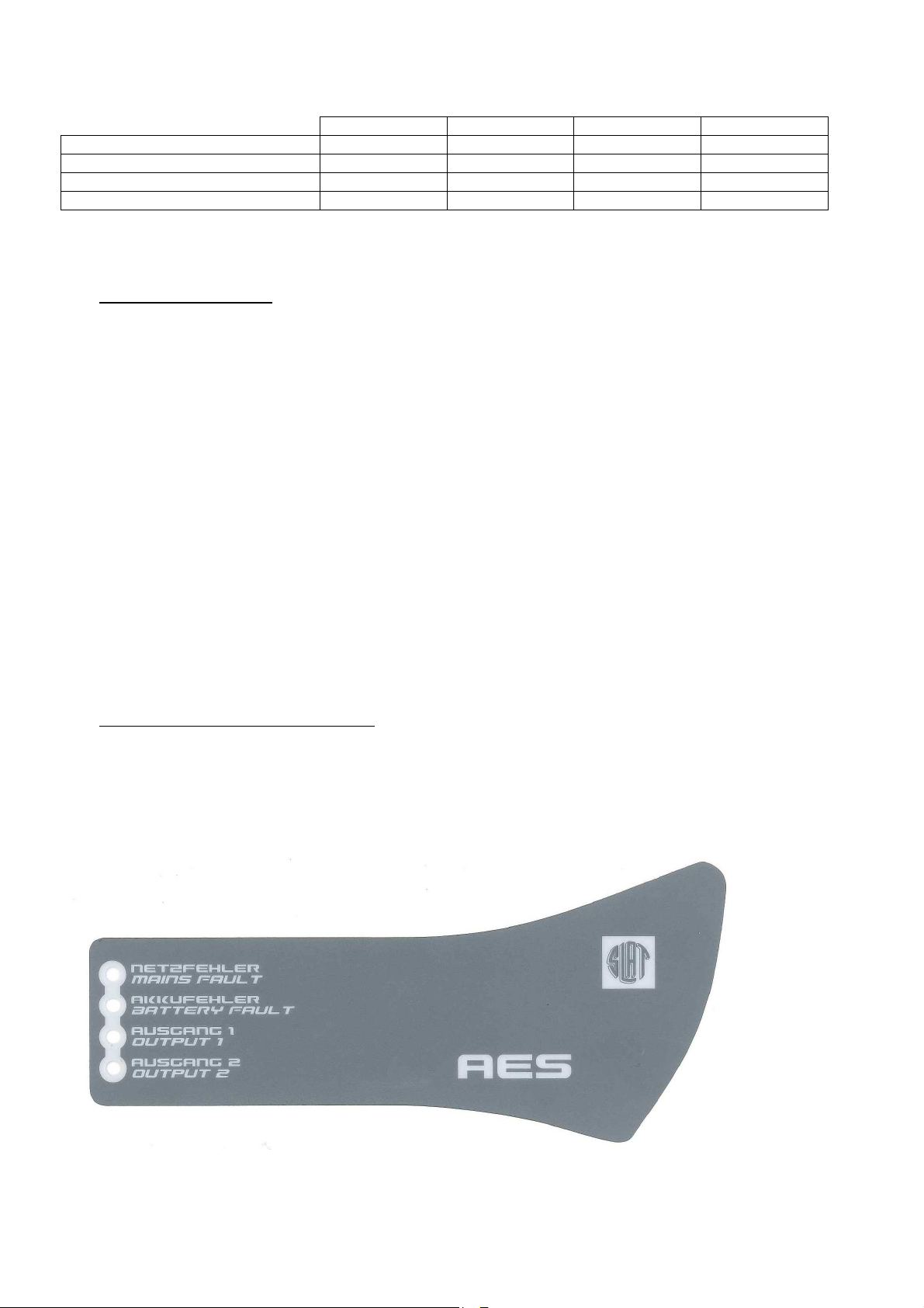
2. Vérifier la tension de sortie utilisation. La LED de la carte mère devient rouge.
3. Fermer le fusible batterie ou raccorder les bornes de la batterie pour les cartes de 50 à 150W.
4. Vérifier le voyant de bon fonctionnement sur la carte mère :
o tout ok : vert,
o défaut secteur : orange,
o défaut batterie ou chargeur ou absence utilisation : rouge (ce défaut est prioritaire par
rapport au défaut secteur).
5. Raccorder le fil de terre et la nappe (si équipé).
6. Fermer le capot .
Votre appareil est en état de marche lorsque les 2 LED vertes correspondant aux sorties utilisation
sont allumées.
5555 Fonctionnement de l’AES
Fonctionnement de l’AES
Fonctionnement de l’AES Fonctionnement de l’AES
5.1 Alarmes
Défaut secteur (source normale) : signalé en local par une LED jaune et à distance par un contact sec RTC
(sécurité positive) avec temporisation
Si le secteur est absent ou <195V.
Si le fusible secteur est HS ou absent.
Si le produit est HS
7
Page 8
Compens
ation en
Coupure tension
Limitation courant
Défaut batterie (source de sécurité) : signalé en local par une LED jaune et à distance par un contact sec
RTC (sécurité positive)
Si la batterie est absente :
Le test batterie s’effectue de la manière suivante :toutes les 30s pendant les 20 premières
minutes après la mise en service : toutes les 15min après les 20 premières minutes, Si un
défaut est détecté, le test repasse toutes les 30s jusqu’à 20 minutes après la disparition du
défaut.
Si l’impédance interne est trop élevée (test toutes les 4h maximum sur une batterie chargée).
Les valeurs limites de l’impédance sont :
24V 48V
50-75W
100-150W
200-300W
400-600W
650mΩ
410mΩ
164mΩ
82mΩ
+/-10%
+/-10%
1,65Ω
+/-10%
656mΩ
+/-10%
328mΩ
-
+/-10%
+/-10%
+/-10%
Si la tension batterie < 1.8V/élt
+/-3%.
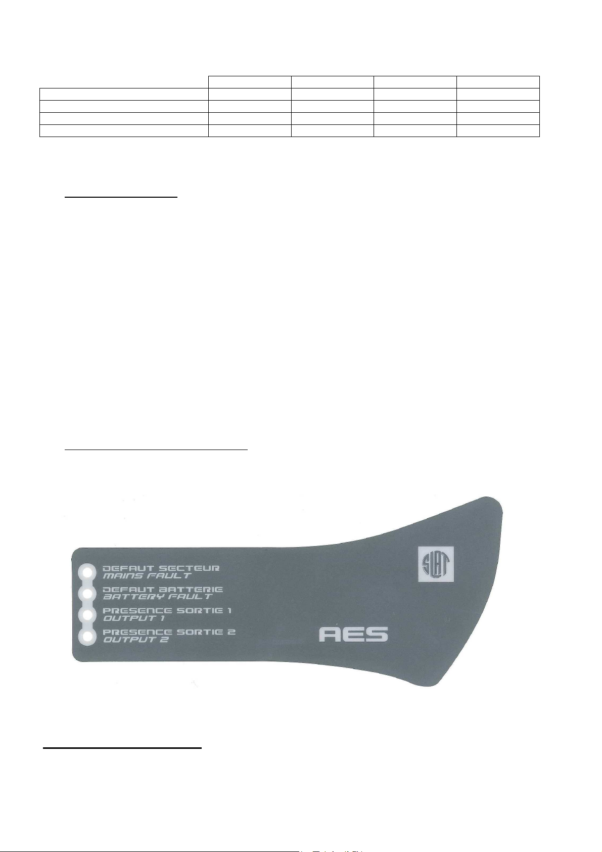
Présence tension de sortie 1 : signalée en local par une LED verte
Présence tension de sortie 2 : signalée en local par une LED verte
Les présences tension de sortie 1 et 2 sont signalées à distances par un contact sec RTC (sécurité positive)
5.2 Récapitulatif des équipements disponibles
Gamme
AES 50 - 75W
AES 150 à 600W
***seuls les modèles AES 50 et 75W certifiés VDS sont équipés d’une sonde.
Compensation en température :
Un système de compensation de la tension batterie permet de maintenir les caractéristiques de
charge dans les limites des spécifications du constructeur batterie sur toute la plage de température
d’utilisation.
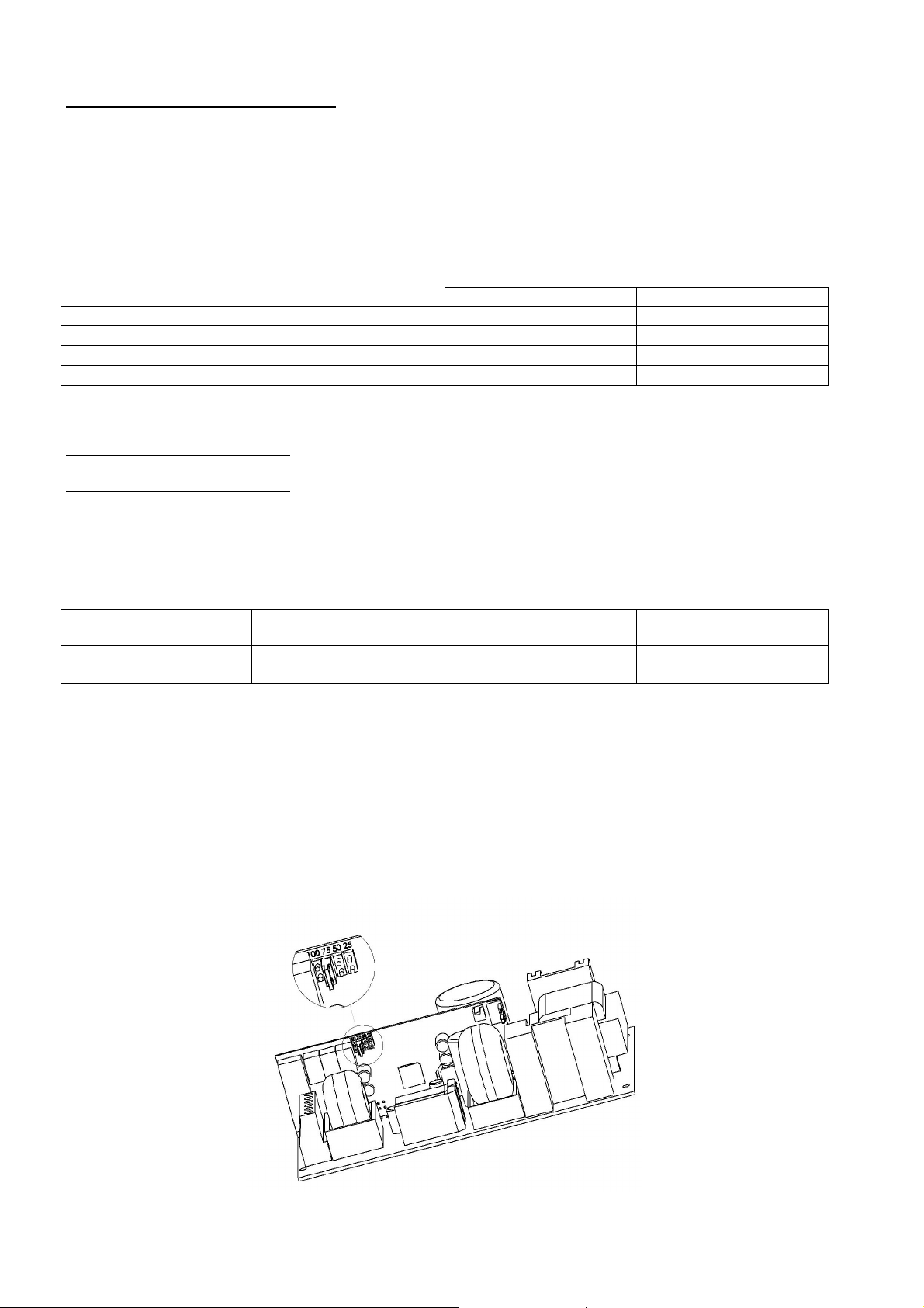
Limitation courant batterie :
Le courant de charge batterie peut être ajusté à 25%, 50%, 75% du courant nominal In à l’aide d’un
cavalier de configuration sur carte fille positions ‘25’, ‘50’, ‘75’.
température
***/
batterie Basse
batterie
/
Cavalier Carte fille
8
Page 9

Coupure tension batterie basse :
Le seuil de coupure est de 1,8V/élt
L’élément effectuant la coupure est positionné dans le +.
6666 La maintenance
La maintenance
La maintenanceLa maintenance
Pour que votre produit vous rende un service maximal et durable, il est vivement conseillé de le maintenir
dans un état de propreté et de veiller à avoir une installation dans un endroit sec et ventilé. Nous ne serions
en aucun cas responsables des dommages liés à une mauvaise utilisation ou à un défaut d’entretien de ce
matériel.
AVERTISSEMENT
Le remplacement de la batterie d’origine par une batterie de type incorrect peut engendrer un risque
d’explosion.
Les batteries usagées doivent être mises au rebut conformément aux obligations de recyclage des matériaux
.
+/- 3%.
7777 Protections fusibles
Protections fusibles
Protections fusiblesProtections fusibles
7.1 Versions 24V
24V
2A
F1 (secteur) : calibre
pouvoir de coupure - taille
F7, F8 (utilisation) :
calibre - type - taille
FBat (batterie) :
calibre - type - taille
5x20 - 1500A
Fusible à réarmement automatique 16A gG
7.2 Versions 48V
48V
2A
F1 (secteur) : calibre
pouvoir de coupure - taille
F7, F8 (utilisation) :
calibre - type - taille
FBat (batterie) :
calibre - type - taille
Fusible à réarmement
24V
3A
3.15A T
3.15A T
5x20
2A T
5x20 - 1500A
3.15A T
5x20
automatique
24V
4A
5x20 - 1500A
48V
3A
2A T
6,3A T
5x20
48V
4A
24V
6A
5x20 - 1500A
12.5A T
24V
8A
5x20 - 1500A
6,3A T
6,3A T
5x20
5x20
6,3A T
12.5A T
5x20
10.3x38
48V
6A
24V
12A
24V
16A
8A T
5x20 - 1500A
25A gG
10.3x38
32A gG
10.3x38
48V
8A
8A T
5x20 - 1500A
12.5A T
5x20
20A aM
10.3x38
24V
24A
48V
12A
9
Page 10

8888 Procédure de dépannage
Procédure de dépannage
Procédure de dépannage Procédure de dépannage
Si l’AES ne délivre pas de tension
• Vérifier la présence secteur sur le bornier secteur
• Vérifier les fusibles
• Vérifier la valeur de la tension sur les bornes util 1et/ou util 2 = tension floating (voir 1.3.2)
• La tension sur les câbles batterie doit être identique à celle de l’utilisation
• Vérifier que chaque batterie de 12Vcc présente une tension égale voir supérieure à 11,5Vcc
• Répéter la mesure après avoir débranché l’utilisation et la batterie.
• Recontrôler la signalisation des voyants (cf chapitre 5 fonctionnement de l’AES)
• Si toutes les étapes sont validées vérifier la compatibilité de votre utilisation
Si la batterie ne prend pas le relais après un défaut secteur
• Contrôler la tension aux bornes de la batterie
• Contrôler le fusible batterie
• Contrôler la tension sur les bornes util 1 et/ou util2
Si les voyants ne sont pas allumés
• Contrôler la présence secteur sur le bornier secteur
• Contrôler le raccordement batterie (et le fusible batterie)
• Contrôler la bonne connection de la nappe
• Contrôler la tension sur les bornes util 1 et/ou util2
Pour une assistance technique complémentaire, contactez la hot line SLAT
Pour vos demandes de retour, connectez vous sur notre site internet
http://www.slat.fr/formulaireRMA.php
ou contactez le SAV SLAT afin d ‘obtenir un numéro RMA (retour de marchandise autorisé)
Sans numéro RMA votre retour ne sera pas accepté.
+ 33 (0) 4 78 66 63 70
10
Page 11

NOTICE D'UTILISATION P 1
BEDIENUNGSANLEITUNG S 11
OPERATING INSTRUCTIONS P 21
GEBRUIKSHANDLEIDING P 31
MANUAL DE USUARIO
P 41
BEDIENUNGSANLEITUNG
AES
50 W bis 600 W
11
Page 12

Inhaltsverzeichnis
1 Allgemeine Daten .................................................................................................. 14
1.1 Vergleichstabelle ............................................................................................................................ 14
1.2 Angaben zur Umweltverträglichkeit ................................................................................................ 14
1.3 Angaben zu den elektrischen Ein- und Ausgängen ....................................................................... 14
2 Montage der Stromversorgung ............................................................................ 15
2.1 Befestigung und Abmessungen der Gehäusekästen (Abm : LxHxP mm) .................................... 15
2.2 Batterien ......................................................................................................................................... 16
3 Anschluss .............................................................................................................. 16
3.1 Anschlussplan ................................................................................................................................. 16
3.2 Maximale Anschlussquerschnitte ................................................................................................... 17
4 Inbetriebnahme ...................................................................................................... 17
5
Funktionsweise von AES ...................................................................................... 17
5.1 Alarme ............................................................................................................................................ 17
5.2 Zusammenfassung der verfügbaren Systeme ............................................................................... 18
6 Wartung .................................................................................................................. 19
7 Sicherungen ........................................................................................................... 19
7.1 Version 24 V ................................................................................................................................... 19
7.2 Version 48 V ................................................................................................................................... 20
8 Fehlerbehebung .................................................................................................... 20
12
Page 13
Herzlichen Glückwunsch,
Sie haben sich für die gesicherte Stromversorgung der Marke SLAT entschieden und dafür danken wir Ihnen.
Sie finden in dieser Bedienungsanleitung alle notwendigen Angaben zu Installation, Inbetriebnahme und Wartung dieses
Geräts.
Für eine reibungslose Funktionsweise des Geräts empfehlen wir Ihnen, diesen Angaben genau zu folgen.
Wir wünschen viel Erfolg.
Sicherheitshinweise
Die Stromversorgung ist dafür ausgelegt, an ein öffentliches 230V Stromverteilernetz angeschlossen zu werden.
Um jegliche Gefahr eines elektrischen Schlags zu verhindern, müssen sämtliche EINGRIFFE bei SPANNUNGSLOS
GESCHALTETEM Gerät (der vorgeschaltete bipolare Schalter ist offen) vorgenommen werden.
Arbeiten bei eingeschaltetem Gerät sind nur bei Eingriffen zulässig, bei denen eine Trennung vom Netz unmöglich ist.
Eingriffe dürfen nur von befugtem Personal vorgenommen werden.
Normen, Richtlinien und Schutz der Umwelt und der öffentlichen Gesundheit
Alle Produkte aus der Baureihe AES halten die NS-Richtlinien und EMV-Normen (bzgl. Störfestigkeit und Emission) ein.
Sie entsprechen den Normen:
• EN 60950-1 (2006) + A11 (2009) + A1 (2010) + A12 (2011) + A2 (2013) (Klasse TBTS)
• EN 61000-6-1(2007), EN 61000-6-2 (2005), EN 61000-6-3 (2007), EN 61000-6-4 (2007) + A1 (2011)
• EN 50130-4 (2011)
• EN 55022 (2006) + A1 (2007) Klasse B
• UL1950 bei den Komponenten.
Sie sind ebenfalls nach den Normen für den jeweiligen Einsatzbereich zertifiziert::
• EN 54-4 (1997) + A1 (2002) + A2 (2006) : Brandmeldeanlagen. Teil 4: Energieversorgungseinrichtungen.
• EN 12101-10 Klasse A (2005): Rauch- und Wärmefreihaltung. Teil 10: Energieversorgung.
• NFS 61940 (2000) : Unterbrechungsfreie Stromversorgungen.
Manche Produkte (24V) entsprechen den Normen :
• VdS 2541 (1996) : Energieversorgungseinrichtungen Anforderungen und Prüfmethoden.
• VdS 2344 (2012) : Procedure for the testing, approval, certification and conformity assessment of products and
systems for fire protection and security technologies.
Alle DoP Nummer und Jahre der CE markierung finden Sie in ANHANG.
Alle Zertifikatnummer finden Sie in unserer Website: http://www.slat.fr/en/certificatsCE.php
SLAT ist seit 2008 gemäß ISO 14001 zertifiziert.
SLAT fertigt alle Produkte in Einhaltung der Umweltschutzbestimmungen RoHS und WEEE.
SLAT lässt die Produkte an deren Lebensdauerende in seiner Wiederaufbereitungsanlage wieder verwerten..
Garantie
Unsere Garantie gilt drei Jahre ab Werk. Sie beschränkt sich auf Erstattung oder Ersatz (je nach unserer Wahl und ohne
Schadenersatz irgendeiner Art) der von uns als schadhaft anerkannten Teilen nach Rücksendung in unser Werk auf
Kosten des Käufers. Wir können den Ersatz oder Reparaturen von Teilen, der bzw. die nicht durch unser Werk erfolgt
sind, nicht akzeptieren. Damit unsere Kunden immer von den neuesten technischen Verbesserungen profitieren können,
behält sich SLAT das Recht vor, an den Produkten die erforderlichen Änderungen vorzunehmen. Die Batterie ist von der
Garantie ausgeschlossen.
13
Page 14
50 W
75 W
100 W
150 W
200 W
300 W
400 W
600 W
0,4 A
0,5 A
0,75 A
1 A 1,5 A
2 A 3 A 4 A
Nennspannung
24 V
48 V
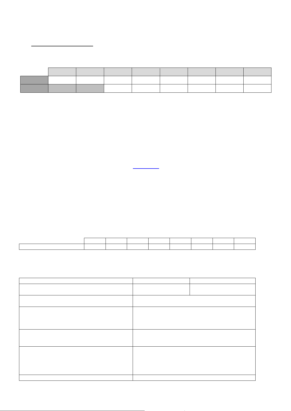
1111 Allgemeine Daten
Allgemeine Daten
Allgemeine DatenAllgemeine Daten
1.1 Vergleichstabelle
24 V 2 A 3 A 4 A 6 A 8 A 12 A 16 A 24 A
48 V 2 A 3 A 4 A 6 A 8 A 12 A
Die angegebenen Stromwerte sind Ströme (In) bei Ausgangsnennleistung
50 W 75 W 100 W 150 W 200 W 300 W 400 W 600 W
1.2 Angaben zur Umweltverträglichkeit
Betriebstemperatur:
-5 °C bis +40 °C bei 100 % Last
-5 °C bis +50 °C bei 75 % Last
-5 °C bis +50 °C bei 100 % Last für 50 bis 100 W
Lagerungstemperatur: -25 bis +85 °C.
Relative Feuchte: 20 bis 95 %
Wärmekapazität : finden Sie auf unserer Website www.slat.fr
Umweltklasse: 1 (nach EN 12101-10)
1.3 Angaben zu den elektrischen Ein- und Ausgängen
1.3.1 Netzeingang
- Spannung, einphasig: 195 V bis 264 V
- Frequenz: 47 bis 63 Hz
- Klasse I.
- Sternpunktbetrieb: TT, TN, IT.
Primärstrom bei 195 V
Ein vorgeschalteter Trennschalter ist vorzusehen: Kurve D.
1.3.2 Ausgang
Geregelte Floating-Spannung bei mittlerer Last
und 25 °C
Die Version AES kann ohne Verbraucherstrom
arbeiten
Der Ausgangsstrom In max kann an einem
Ausgang oder teilweise an beiden Ausgängen
abgenommen werden.
Der angegebene max. Ausgangsstrom kann
dauerhaft geliefert werden. (C = Batteriekapazität)
Der angegebene max. Ausgangsstrom, der höher
als I max ist, kann für eine kurze Zeit geliefert
werden. In dieser zeit ist kein Laden der Batterie
erforderlich.
Unterbrechungszeit 0s
14
27,2 V
+/-0,5 %
54,4 V
Imin = 0
I max a = In –C/20
I max b = In
In
+/-0,5 %
Page 15
1.3.3 Batteriebetrieb
24 V
48 V
Angaben zur Autarkie der AES-Stromversorgung und zur Batteriecodierung finden Sie auf unserer Website:
www.slat.fr
1.3.4 Zulässige Batteriekapazitäten
50W von 7 bis 38Ah von 2.1 bis 12Ah
75W von 7 bis 55Ah von 2.1 bis 12Ah
100W von 7 bis 55Ah von 2.1 bis 12Ah
150W von 7 bis 86Ah von 2.1 bis 12Ah
200W von 7 bis 110Ah von 4 bis 65Ah
300W von 7 bis 166Ah von 4 bis 65Ah
400-600W von 7 bis 225Ah von 4 bis 140Ah
Prüfen, dass die Batterien gut mit den gültigen Normen in den Ländern im Einklang stehen, wo sie benutzt werden.
2 Montage der Stromversorgung
Montage der Stromversorgung
Montage der StromversorgungMontage der Stromversorgung
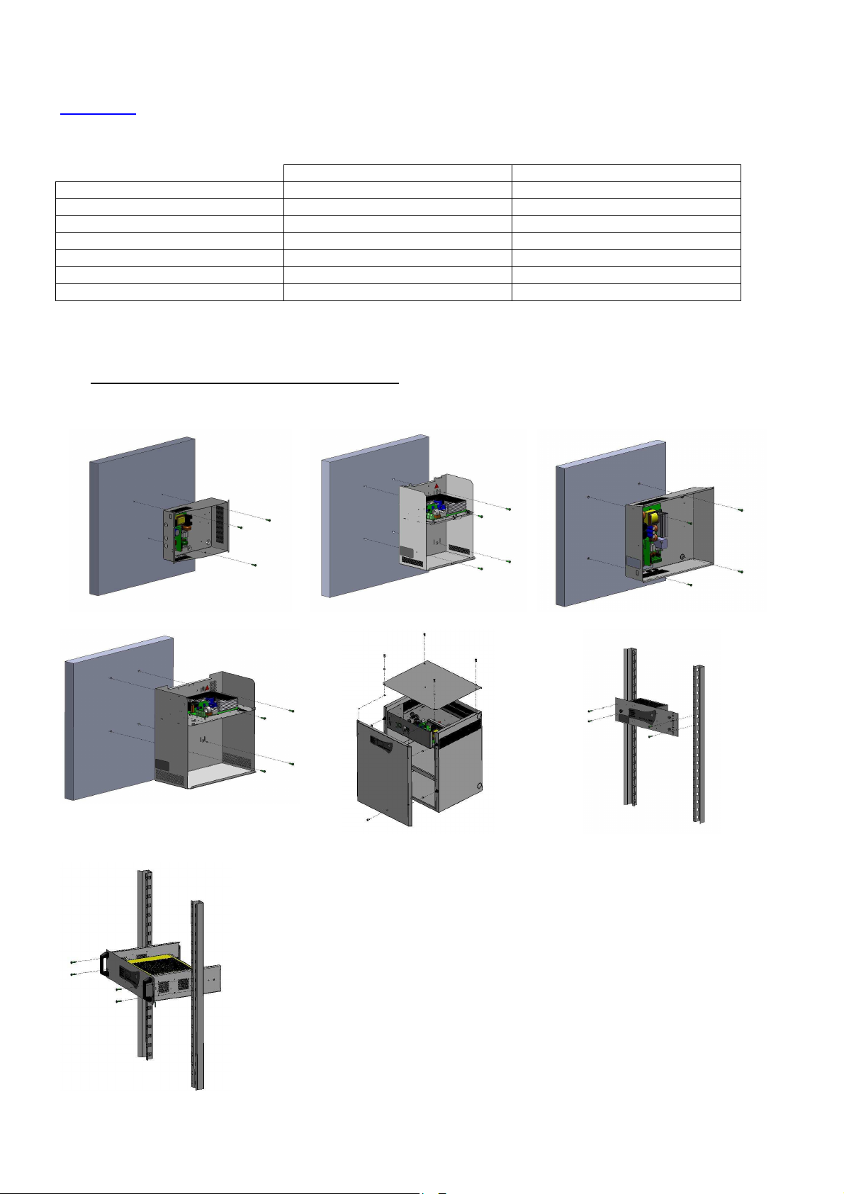
2.1 Befestigung und Abmessungen der Gehäusekästen (Abm : LxHxP mm)
C24 - Dim : 322x248x126mm - IP 30
C85 – Dim : 408x408x224mm – IP31
C38 – Dim : 289x350x189mm - IP 31 C48 – Dim : 425x345x120mm - IP30
C180 – Dim : 505x610x430mm – IP31
RackF3U – Dim : 482x133x110mm –
IP30
Rack 3U – Dim : 483x132x358mm – IP30
15
Page 16
2.2 Batterien
Das Einbau- und Verkabelungsschema für die Batterien wird im Produkt-Kit mitgeliefert (außer Rack und
F3U).
Der Temperaturmessfühler für die Batterie sollte direkt neben der Batterie angebracht werden.
3 Anschluss
Anschluss
AnschlussAnschluss
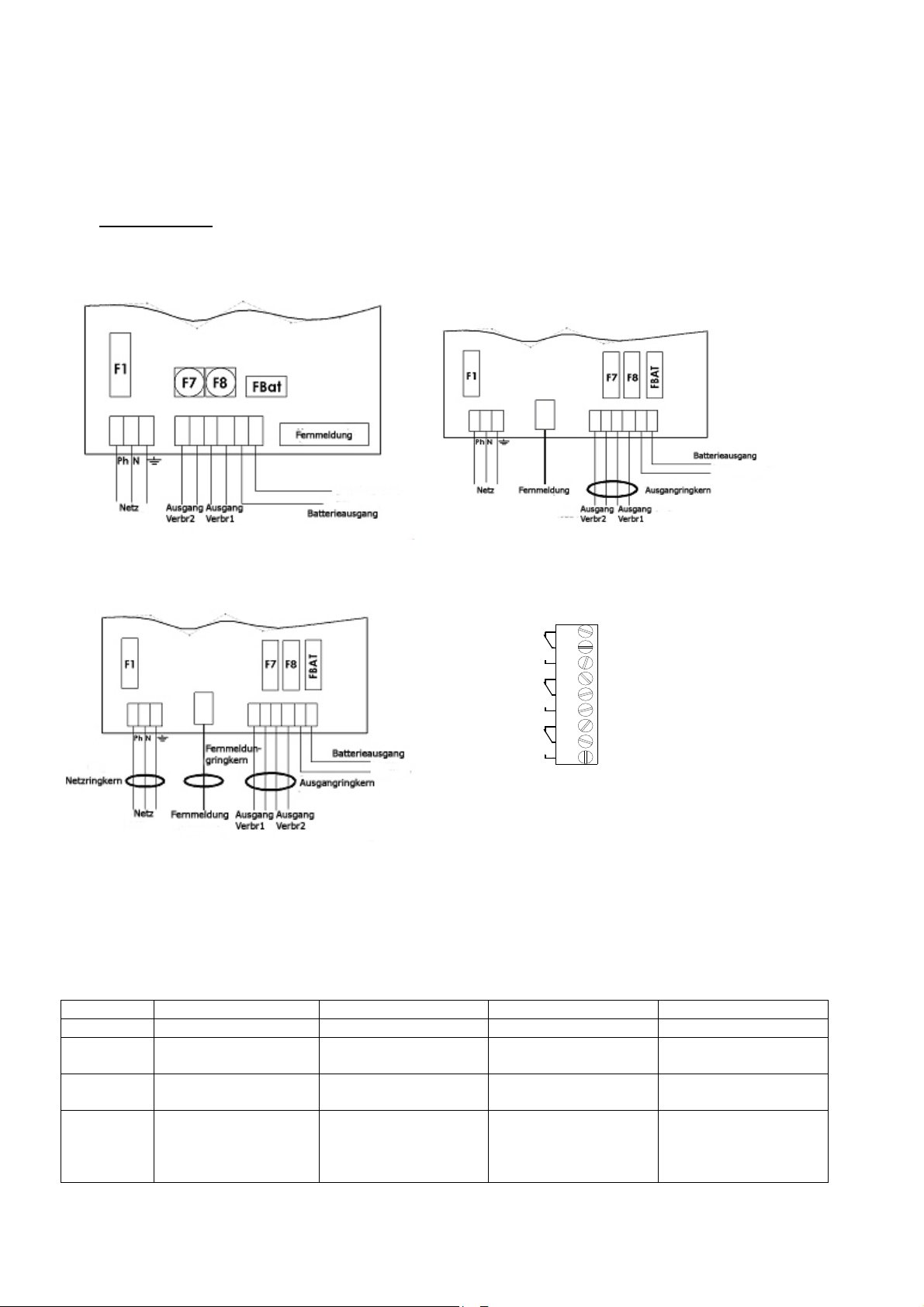
3.1 Anschlussplan
Verkabelung 50-75 W Verkabelung 100-300 W
NC
NO
NC
NO
NC
NO
NC : N o rm a ll y C los e d
NO : N o r m a ll y O p e n e d
Verkabelung 400- 600W Verkabelung Femmeldung
1
Netz
2
3
4
Batterie
5
6
7
8
9
Ausgang
* Mit der mitgelieferten Schelle kann das Netzkabel an Stelle der Netzklemmleiste befestigt werden.
Achtung! Die im Gehäuse vorgesehenen Öffnungen müssen verwendet werden. Bohren Sie keine
zusätzlichen Öffnungen in das Gehäuse. Dies könnte zum Ausfall des Geräts und Verlust der Garantie
führen.
Tabelle für die Ringkerne Verwendung (Ah/20h – 1.75V/ Zelle)
C24-C48 C38-C85 F3U Rack-C180
50-75 W Kein Kein Kein -
100-150 W Ringkern Ausgang zu
montieren
200-300 W Ringkern Ausgang zu
montieren
400-600 W
Ringkern Netz +
Ringkern Reporte
Ringkern Ausgang zu
montieren
Ringkern Ausgang
vormontiert
Ringkern Ausgang
vormontiert
- - Filter/Ringkern Netz +
Ringkern Ausgang zu
montieren
- Ringkern Ausgang
-
vormontiert
Ringkern Reporte
Ringkern Ausgang
vormontiert
16
Page 17
3.2 Maximale Anschlussquerschnitte
50-
75 W
100-150 W
200-300 W
400-600 W
Netz 2,5 mm² 2,5 mm² 2,5 mm² 2,5 mm²
Batterien 2,5 mm² 6 mm² 6 mm² 10 mm²
Verbraucher (2 Ausgänge) 2,5 mm² 6 mm² 6 mm² 10 mm²
Alarmreporte (abziehbar) 1,5 mm² 1,5 mm² 1,5 mm² 1,5 mm²
4444 Inbetriebnahme
Inbetriebnahme
Inbetriebnahme Inbetriebnahme
Öffnen Sie die Batteriesicherung, oder bei den Platinen (50 bis 150 W) mit selbstrückstellender Sicherung,
schließen Sie die Drähte der Batterie an die Klemmleiste an, aber schließen Sie die Batterieklemmen noch
nicht an.
Nachdem die elektrischen Anschlüsse hergestellt sind (Netz, Verbraucher und Batterien):
1. Schließen Sie den vorgeschalteten Netztrennschalter.
2. Prüfen Sie die Verbraucherausgangsspannung. Die LED auf der Hauptplatine muss rot leuchten.
3. Schließen Sie die Batteriesicherung oder bei den Platinen (50 bis 150 W) schließen Sie die
Batterieklemmen wieder an.
4. Prüfen Sie, ob die Kontrollleuchte auf der Hauptplatine den ordnungsgemäßen Betrieb anzeigt:
o alles OK: grün
o Netzstörung: orange
o Störung Batterie oder Ladegerät oder Abwesen der Ausgangspannung: rot (diese
Störung ist vorrangig gegenüber der Netzstörung).
5. Verbinden Sie Erdleiter und Bandkabel auf die Abdeckung (falls vorhanden).
6. Schließen Sie die Abdeckung.
Ihr Gerät befindet sich im ordnungsgemäßen Betriebszustand, wenn die beiden grünen LEDs für die
Verbraucherausgänge leuchten.
5 Funktionsweise von AES
Funktionsweise von AES
Funktionsweise von AES Funktionsweise von AES
5.1 Alarme
17
Page 18

Abschaltung bei NS der
Batterie
-
Netzstörung (Normalstromquelle): Sie wird einerseits lokal durch eine gelbe LED und auch fern über einen
potenzialfreien NO-NC-Kontakt (selbstsicher) mit Verzögerung angezeigt.
Wenn keine Netzspannung anliegt oder < 195 V
Wenn die Netzsicherung außer Betrieb oder nicht vorhanden ist
Wenn das Gerät nicht angeschlossen ist
Batteriestörung (Notstromquelle): Sie wird einerseits lokal durch eine gelbe LED und auch fern über einen
potenzialfreien NO-NC-Kontakt (selbstsicher) angezeigt.
Wenn keine Batterie ordnungsmässig geschaltet wird:
Der Batterietest wird wie folgt ausgeführt: alle 30 s während der ersten 20 min nach
Inbetriebnahme: alle 15 min nach den ersten 20 min. Falls eine Störung auftritt, wird der Test
alle 30 s wiederaufgenommen bis 20 min über das Verschwinden der Störung hinaus
ausgeführt.
Wenn die interne Impedanz zu hoch ist (Test max. alle 4 h mit einer geladenen Batterie).
Die Impedanzgrenzwerte sind wie folgt:
24 V 48 V
50-75 W
100-150 W
200-300 W
400-600 W
650 mΩ
410 mΩ
164 mΩ
82 mΩ
+/-10 %
+/-10 %
1,65 Ω
+/-10 %
656 mΩ
+/-10 %
328 mΩ
-
+/-10 %
+/-10 %
+/-10 %
Wenn die Batteriespannung < 1,8 V/Zelle
+/-3 %
.
Anliegen von Spannung an Ausgang 1: Wird lokal über eine grüne LED angezeigt.
Anliegen von Spannung an Ausgang 2: Wird lokal über eine grüne LED angezeigt.
Das Anliegen von Spannung an den Ausgängen 1 und 2 wird fern über einen potenzialfreien NO-NC-Kontakt
(selbstsicher) angezeigt.
5.2 Zusammenfassung der verfügbaren Systeme
Produktreihe Temperaturausgleich
AES 50 – 75 W ***/
AES 150 bis 600 W
***nur die nach VDS zertifizierten Modelle AES 50 und 75 W sind mit einem Temperaturfühler
ausgestattet.
Temperaturausgleich:
Ein Ausgleichssystem der Batteriespannung ermöglicht die Aufrechterhaltung der Ladungskenndaten
innerhalb der Spezifikationsgrenzen des Batterieherstellers über den gesamten Bereich der
Nutzungstemperatur.
Batteriestrombegrenzung:
Der Ladestrom der Batterie kann auf 25 %, 50 % und 75 % des Nennstroms In eingeregelt werden.
Dazu ist der Jumper auf der Tochterplatine auf die entsprechenden Stellungen ‘25’, ‘50’, ‘75’ zu
schieben.
Batterie
strombegrenzung
/
18
Page 19
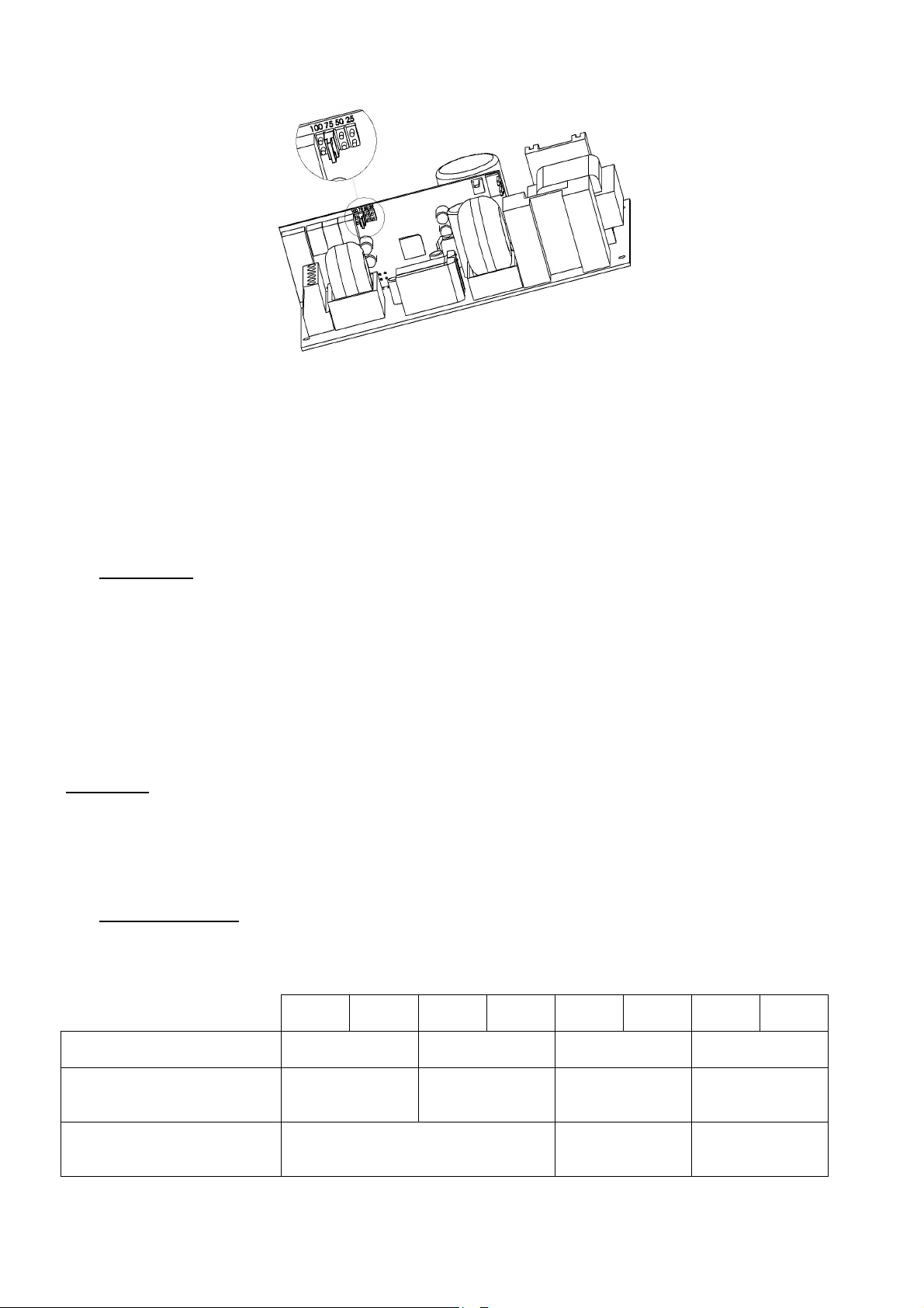
Jumper auf Tochterplatine
Abschaltung bei Niederspannung der Batterie:
Die Abschaltschwelle liegt bei 1,8 V/Zelle ±3 %.
Das Bauteil, das die Abschaltung vornimmt, liegt im Plus-Bereich.
6 Wartung
Wartung
WartungWartung
Damit Ihr Gerät optimal und zuverlässig arbeitet, empfehlen wir dringend, auf absolute Sauberkeit zu achten
und das Gerät an einem trockenen und gut belüfteten Ort aufzustellen. Wir können nicht für Schäden in
Verbindung mit unsachgemäßer Verwendung oder Wartungsfehlern haftbar gemacht werden.
WARNUNG
Der Ersatz der Originalbatterie durch eine Batterie eines anderen Typs kann zur Explosion führen.
Verbrauchte Batterien müssen gemäß den Recycling-Bestimmungen entsorgt werden.
7 Sicherungen
Sicherungen
SicherungenSicherungen
7.1 Version 24 V
24 V
2 A
F1 (Netz): Sicherungseinsatz
Abschaltvermögen - Größe
F7, F8 (Verbraucher):
Sicherungseinsatz – Typ Größe
FBat (Batterie):
Sicherungseinsatz – Typ Größe
3,15 A T
5x20 – 1500 A
3,15 A T
Sicherung mit automatischer
24 V
3 A
5x20
Wiedereinschaltung
24 V
4 A
5x20 – 1500 A
19
2 A T
6,3 A T
5x20
24 V
6 A
24 V
8 A
5x20 – 1500 A
12,5 A T
16 A gG
10,3x38
24 V
12 A
6,3 A T
5x20
24 V
16 A
5x20 – 1500 A
24 V
24 A
8 A T
25 A gG
10,3x38
32 A gG
10,3x38
Page 20

7.2 Version 48 V
48 V
2 A
F1 (Netz): Sicherungseinsatz
Abschaltvermögen - Größe
F7, F8 (Verbraucher):
Sicherungseinsatz – Typ Größe
FBat (Batterie):
Sicherungseinsatz – Typ Größe
8 Fehlerbehebung
Fehlerbehebung
Fehlerbehebung Fehlerbehebung
Wenn AES keine Spannung liefert
• Prüfen Sie, ob Netzspannung an der Netzklemmleiste anliegt.
• Prüfen Sie die Sicherungen.
• Prüfen Sie den Spannungswert an den Klemmen Verbr1 und/oder Verbr2 = Floating-Spannung
(siehe 1.3.2).
• Die Spannung in den Batteriekabeln muss der Verbraucherspannung entsprechen.
• Prüfen Sie, ob jede 12 Vcc-Batterie dieselbe Spannung hat, das heißt mehr als 11,5 Vcc bzw. 6/5,7
oder 2/1,9 Vcc.
• Wiederholen Sie die Messung, nachdem Sie Verbraucher und Batterie abgetrennt haben.
• Kontrollieren Sie erneut die LEDs (s. Kap. 5 „Funktionsweise“ der Stromversorgung AES).
• Nachdem Sie alle Schritte ausgeführt haben, prüfen Sie die Kompatibilität Ihrer Verbraucher.
Wiedereinschaltung
2 A T
5x20 – 1500 A
3,15 A T
5x20
Sicherung mit
automatischer
48 V
3 A
48 V
4 A
6,3 A T
5x20 – 1500 A
6,3 A T
5x20
12,5 A T
5x20
48 V
6 A
48 V
8 A
8 A T
5x20 – 1500 A
12,5 A T
5x20
20 A aM
10,3x38
48 V
12 A
Wenn die Batterie nach einer Netzstörung nicht ihre Aufgabe übernimmt
• Kontrollieren Sie die Spannung an den Batterieklemmen.
• Kontrollieren Sie die Batteriesicherung.
• Kontrollieren Sie die Spannung an den Klemmen Verbr1 und/oder Verbr2.
Wenn die Kontrollleuchten nicht leuchten
• Prüfen Sie, ob Netzspannung an der Netzklemmleiste anliegt.
• Kontrollieren Sie den Batterieanschluss (und die Batteriesicherung).
• Kontrollieren Sie den einwandfreien Anschluss des Bandkabels.
• Kontrollieren Sie die Spannung an den Klemmen Verbr1 und/oder Verbr2.
Falls Sie weitere technische Unterstützung benötigen, rufen Sie die SLAT-Hotline an unter
Im Falle von Retouranfragen gehen Sie auf unsere Website unter
http://www.slat.fr/formulaireRMA.php
oder wenden Sie sich an den SLAT-Kundenservice, um eine RMA-Nummer (autorisierte
+ 33 (0) 4 78 66 63 70
Warenrücksendung) zu erhalten.
Ohne diese RMA-Nummer können wir Ihre Rücksendung leider nicht annehmen.
20
Page 21

NOTICE D'UTILISATION P 1
BEDIENUNGSANLEITUNG S 11
OPERATING INSTRUCTIONS P 21
GEBRUIKSHANDLEIDING P 31
MANUAL DE USUARIO
P 41
OPERATING INSTRUCTIONS
AES
50 W to 600 W
21
Page 22

Table of contents
1 General information ............................................................................................... 24
1.1 Correspondence table .................................................................................................................... 24
1.2 Environmental specifications .......................................................................................................... 24
1.3 Electrical input and output specifications ....................................................................................... 24
2 Installation of your equipment .............................................................................. 25
2.1 Mounting and cabinet dimensions (dim.: LxHxW mm) ................................................................... 25
2.2 Batteries .......................................................................................................................................... 26
3 Connection ............................................................................................................. 26
3.1 Connection diagram ....................................................................................................................... 26
3.2 Maximum connection sizes ............................................................................................................ 27
4 Commissioning ...................................................................................................... 27
5
AES Operation ........................................................................................................ 27
5.1 Alarms ............................................................................................................................................. 27
5.2 Summary of available equipment ................................................................................................... 28
6 Maintenance ........................................................................................................... 29
7 Fuse protections .................................................................................................... 29
7.1 24 V versions .................................................................................................................................. 29
7.2 48 V versions .................................................................................................................................. 29
8 Troubleshooting procedure .................................................................................. 30
22
Page 23
Congratulations,
You have just acquired an emergency power supply by SLAT, and we thank you for your choice.
This manual includes instructions for the installation, commissioning and maintenance of this equipment.
In order for the equipment to work properly, we recommend that these instructions be followed very carefully.
Good installation.
Safety precautions
This equipment is designed to be connected to the 230 V public distribution network.
To avoid any risk of electric shock, all INTERVENTIONS must be carried out with the equipment SWITCHED OFF
(upstream two-pole circuit-breaker open).
Interventions with the equipment switched on are authorized only when it is impossible to switch the equipment off. The
operation must only be performed by qualified personnel.
Standards, directives and protection of the environment and public health
All products of the SONaes range are compliant with LV and EMC directives (immunity and emission). They are compliant
with standards:
• EN 60950-1 (2006) + A11 (2009) + A1 (2010) + A12 (2011) + A2 (2013) (TBTS class)
• EN 61000-6-1(2007), EN 61000-6-2 (2005), EN 61000-6-3 (2007), EN 61000-6-4 (2007) + A1 (2011)
• EN 50130-4 (2011)
• EN 55022 (2006) + A1 (2007) class B
• UL1950 for components.
They are also certified compliant with the following trade standards:
• EN 54-4 (1997) + A1 (2002) + A2 (2006) : Fire detection and fire alarm systems. Part 4: power supply equipment.
• EN 12101-10 class A (2005): Smoke and heat control systems. Part 10: power supplies.
• NFS 61940 (2000) : Fire Safety Systems - Electrical power supplies as safety devices.
Some products (24V) are compliant with standards:
• VdS 2541 (1996) : Energieversorgungseinrichtungen Anforderungen und Prüfmethoden.
• VdS 2344 (2012) : Procedure for the testing, approval, certification and conformity assessment of products and
systems for fire protection and security technologies.
The DoP numbers and CE marking years are available on APPENDIX.
All certificates are available on our website: http://www.slat.fr/en/certificatsCE.php
SLAT is ISO 14001 certified since 2008.
SLAT manufactures all its products in accordance with RoHS and WEEE environmental directives.
SLAT recycles its products at the end of their service life through its recycling programme.
Warranty
Our warranty is three years from the date of delivery (ex-works). It is strictly limited to reimbursement or replacement (at
our discretion and without compensation of any sort) of parts recognised as faulty by our services, following return of the
product to our premises at the buyer's expense. The replacement or repair of equipment is possible only on our premises.
In order to allow our customers to benefit from the latest technical improvements, SLAT reserves the right to make all
necessary modifications to its products. The battery is not included in the warranty.
23
Page 24
50 W
75 W
100 W
150 W 200 W
300 W
400 W 600 W
0.4 A
0.5 A
0.75 A
1 A 1.5 A
2 A 3 A 4 A
Rated voltage
24 V
48 V
1 General information
General information
General informationGeneral information
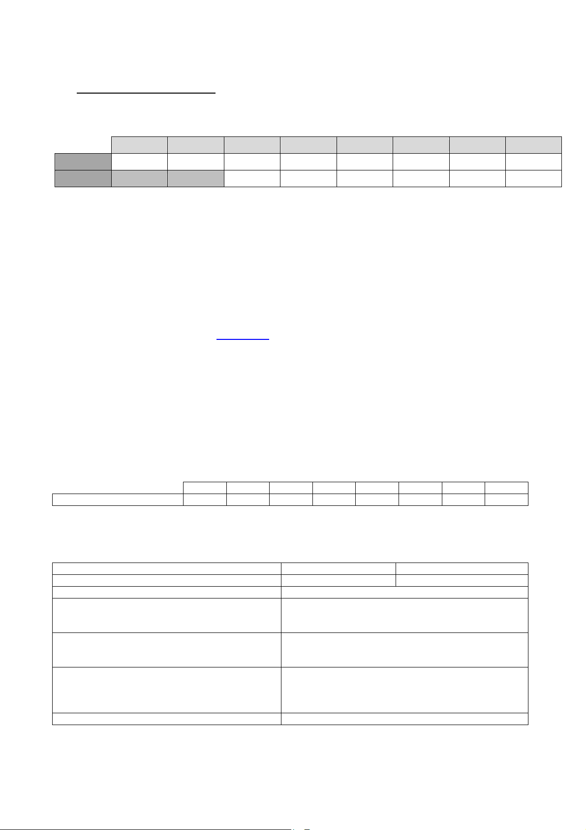
1.1 Correspondence table
24 V 2 A 3 A 4 A 6 A 8 A 12 A 16 A 24 A
48 V 2 A 3 A 4 A 6 A 8 A 12 A
The currents (In) shown are at rated output power.
50 W 75 W 100 W 150 W 200 W 300 W 400 W 600 W
1.2 Environmental specifications
Operating temperature:
-5 °C to +40 °C at 100 % charge.
-5 °C to +50 °C at 75 % charge.
-5 °C to +50 °C at 100 % charge for 50 W to 100 W.
Storage temperature: -25 to +85 °C.
Relative humidity: 20 to 95 %.
Heat capacity consult our website: www.slat.fr
Environment class: 1 (according to EN 12101-10)
1.3 Electrical input and output specifications
1.3.1 Network input
- single-phase voltage: 195 V to 264 V.
- frequency: 47 to 63 Hz.
- class I.
- neutral systems: TT, TN, IT.
Primary current @ 195 V
Circuit breaker to be provided upstream: D curve
1.3.2 Output
Floating voltage set at half-load and at 25 °C. 27.2 V
The AES version can function without load current
The output current In max. can be used on a
single outlet or distributed among all outlets.
Maximum specified output current that can be
supplied continuously. (C=battery capacity).
Maximum specified output current greater than I
max a, that can be supplied for a short period of
time during which battery charging is not required.
Switching time 0s
24
±0.5 %
54.4 V
Imin = 0
In
I max a = In –C/20
I max b = In
±0.5 %
Page 25
1.3.3 Autonomy
24 V
48 V
To determine the autonomy of your AES and interpret the battery code dates, consult our website:
www.slat.fr
1.3.4 Authorized battery capacities (Ah/20h – 1.75V/ elt)
50W 7 to 38Ah 2.1 to 12Ah
75W 7 to 55Ah 2.1 to 12Ah
100W 7 to 55Ah 2.1 to 12Ah
150W 7 to 86Ah 2.1 to 12Ah
200W 7 to 110Ah 4 to 65Ah
300W 7 to 166Ah 4 to 65Ah
400-600W 7 to 225Ah 4 to 140Ah
Check that the batteries are in conformity with the standards effective in the countries where they are used.
2 Installation of your equipment
Installation of your equipment
Installation of your equipmentInstallation of your equipment
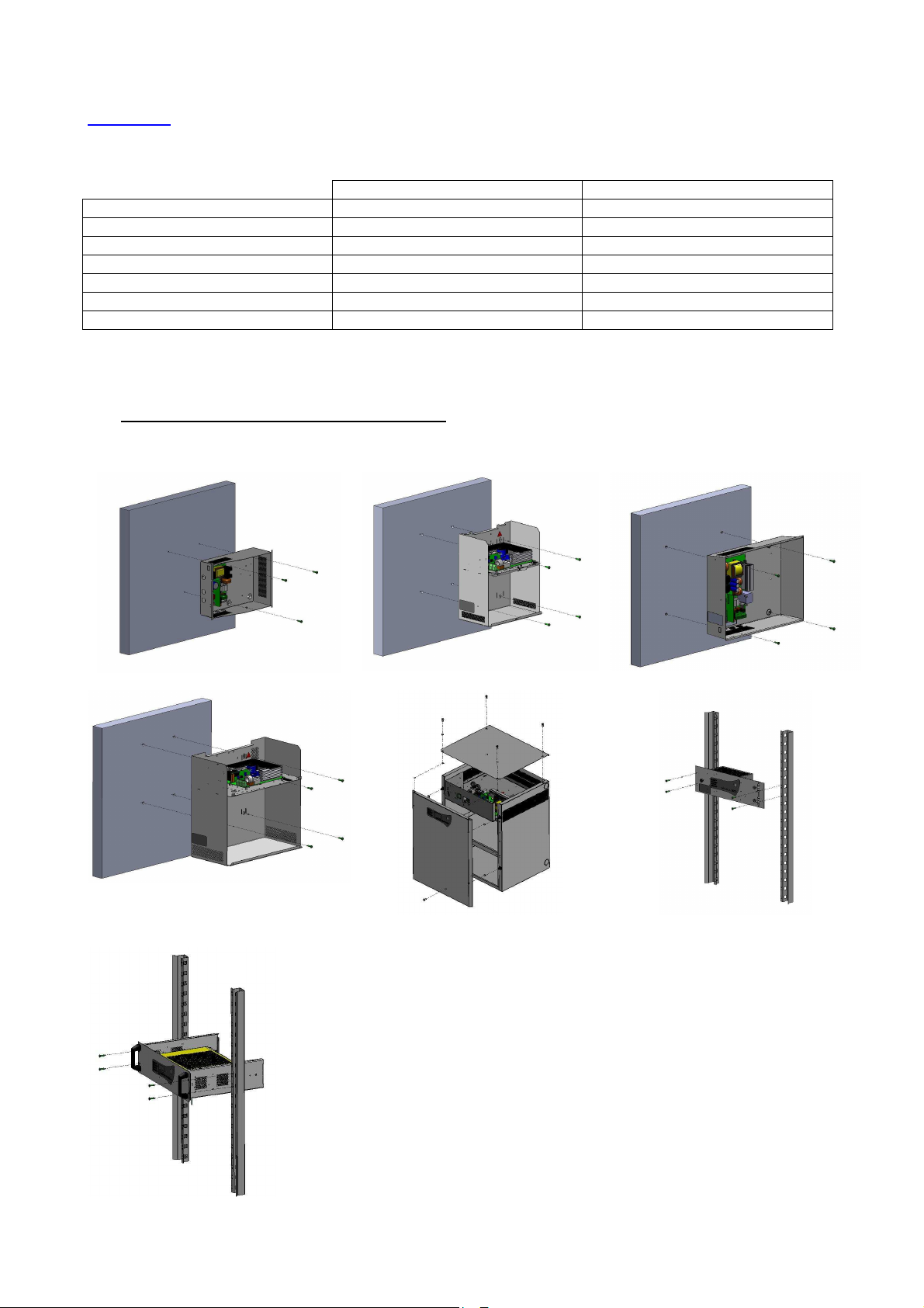
2.1 Mounting and cabinet dimensions (dim.: LxHxW mm)
C24 - Dim : 322x248x126mm - IP 30
C85 – Dim : 408x408x224mm – IP31
C38 – Dim : 289x350x189mm - IP 31 C48 – Dim : 425x345x120mm - IP30
C180 – Dim : 505x610x430mm – IP31
RackF3U – Dim : 482x133x110mm –
IP30
Rack 3U – Dim : 483x132x358mm – IP30
25
Page 26
2.2 Batteries
A battery integration drawing and wiring schematic is included in the kit supplied with the product (except the
rack and F3U).
The battery temperature sensor must be placed as close to the battery as possible.
3 Connection
Connection
ConnectionConnection
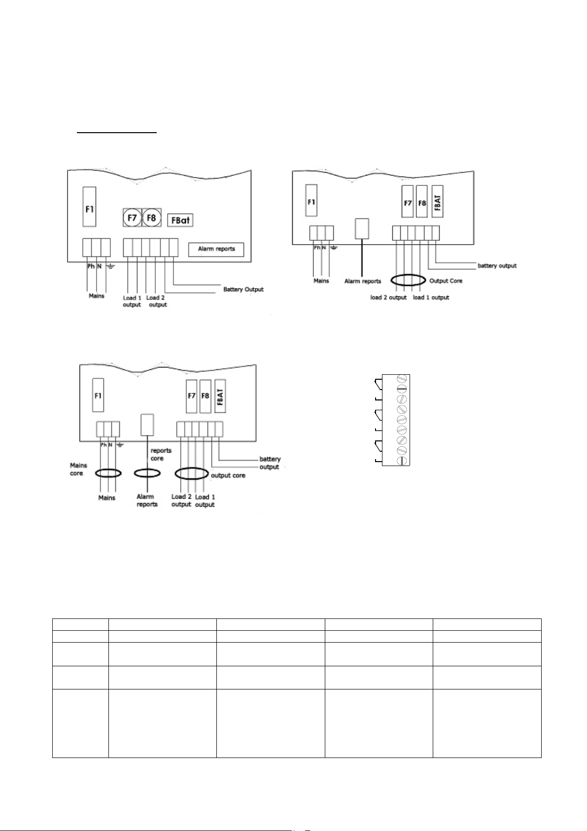
3.1 Connection diagram
50-75 W wiring 100-300 W wiring
NC
NO
NC
NO
NC
NO
NC : N o r m a lly Clo s e d
NO : N or m a l ly O p e ne d
1
2
3
4
5
6
7
8
9
Mains
Battery
Output
400-600 W wiring Alarms reports wiring
* The cable tie included with all the products allows the mains cable to be secured to the mains terminal strip.
Important: the openings provided in the cabinet must be used. Do not create additional openings as
doing so may casue the device to malfunction and voids the warranty.
Core use table
C24-C48 C38-C85 F3U Rack-C180
50-75 W None None None -
100-150 W OUTPUT CORE to be
installed
200-300 W OUTPUT CORE to be
installed
400-600 W
MAINS CORE +
REPORTS CORE +
OUTPUT CORE to be
installed
OUTPUT CORE pre-
installed
OUTPUT CORE pre-
installed
- - FILTER/MAINS CORE
OUTPUT CORE to be
installed
- OUTPUT CORE pre-
-
installed
+
REPORTS CORE +
OUTPUT CORE pre-
installed
26
Page 27
3.2 Maximum connection sizes
50-75 W
100-150 W
200-300 W
400-600 W
Mains 2.5 mm² 2.5 mm² 2.5 mm² 2.5 mm²
Batteries 2.5 mm² 6 mm² 6 mm² 10 mm²
Load (2 outputs) 2.5 mm² 6 mm² 6 mm² 10 mm²
Alarm reports* (unpluggable) 1.5 mm² 1.5 mm² 1.5 mm² 1.5 mm²
4 Commissioning
Commissioning
CommissioningCommissioning
Open the battery fuse, or for 50 W to 150 W boards equipped with an automatic reset fuse: connect the
battery wires to the terminal strip, but do not connect the battery terminals.
After the electrical connections are made (mains, loads and batteries).
1. Close the upstream mains circuit-breaker.
2. Check the load output voltage. The LED on the motherboard turns red.
3. Close the battery fuse or connect the battery terminals for 50 W to 150 W boards.
4. Check that the LED confirming correct motherboard operation is illuminated:
o all OK: green,
o mains fault: orange,
o battery or charger fault, or load not present: red (this fault takes priority over a mains
fault).
5. Connect the ground wire and the wire ribbon (if equipped).
6. Close the cover.
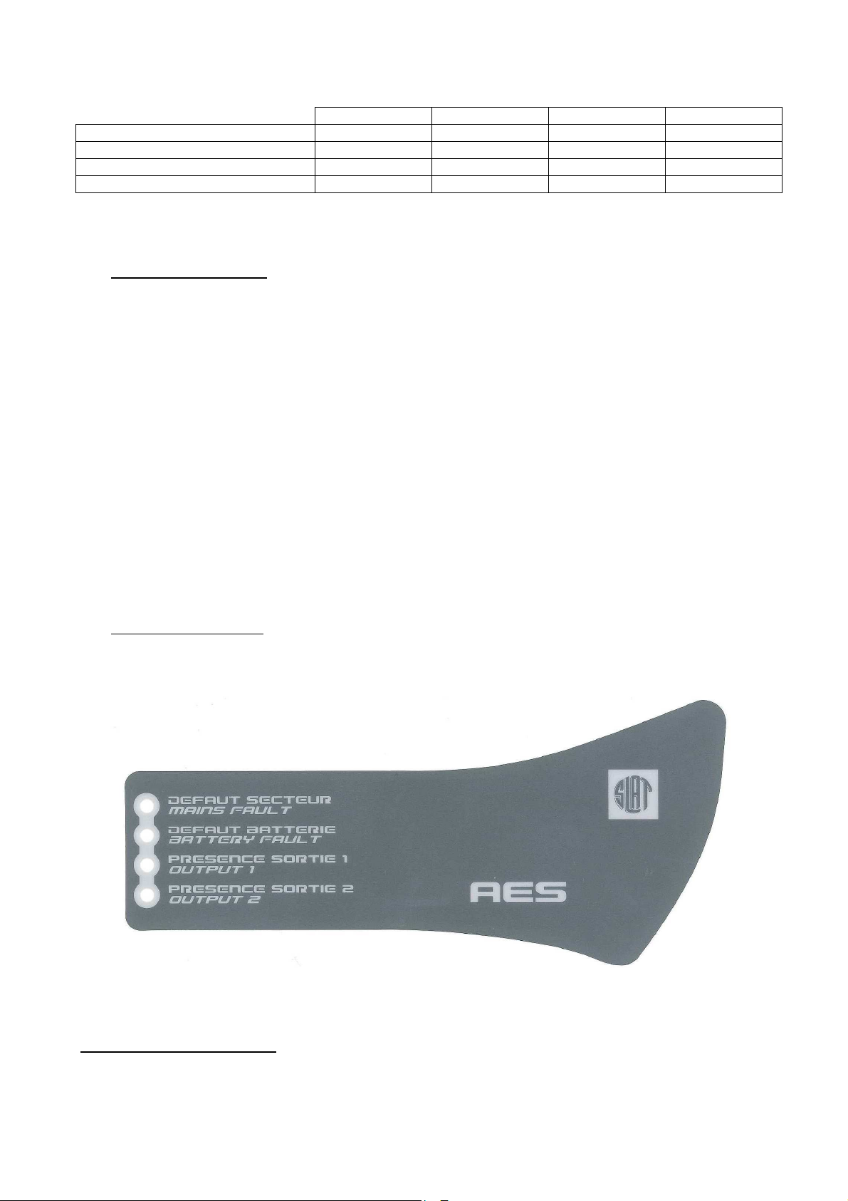
Your equipment is in operation when the 2 green LEDs, corresponding to the load outputs, are
illuminated.
5 AES Operation
AES Operation
AES OperationAES Operation
5.1 Alarms
Mains fault (normal source): signalled locally by a yellow LED and remotely by dry contact with delay
(failsafe).
If the mains is not present or < 195 V.
If the mains fuse is blown or not present.
If the product is out of service.
27
Page 28
Temperature
Battery low voltage cut
-
Battery current
Battery fault (emergency power): signalled locally by a yellow LED and remotely by dry contact with delay
(failsafe).
If the battery is not present:
The battery test is performed in the following manner: every 30 seconds for the first 20
minutes after commissioning: every 15 minutes after the first 20 minutes. If a fault is detected,
the test is performed every 30 seconds up to 20 minutes after the fault disappears.
If the internal impedance is too high (test every 4 hours maximum on a charged battery).
The impedance limit values are:
24 V 48 V
50-75 W
100-150 W
200-300 W
400-600 W
650mΩ
410mΩ
164mΩ
82mΩ
±10 %
±10 %
1,65Ω
±10 %
656mΩ
±10 %
328mΩ
-
+/-10%
±10 %
±10 %
If the battery voltage < 1.8 V/cell
±3 %.
Output 1 voltage presence : signalled locally by a green LED
Output 2 voltage presence : signalled locally by a green LED
Voltage presence on output 1 and 2 is signalled by a dry contact with delay (failsafe).
5.2 Summary of available equipment
Range
AES 50 W - 75 W ***/
AES 150 W to 600 W
***only VDS-certified AES 50 and 75 W models are equipped with a sensor.
Temperature compensation:
A battery voltage compensation system maintains the charge characteristics within the limits specified
by the battery manufacturer across the entire operational temperature range.
Battery current limitation:
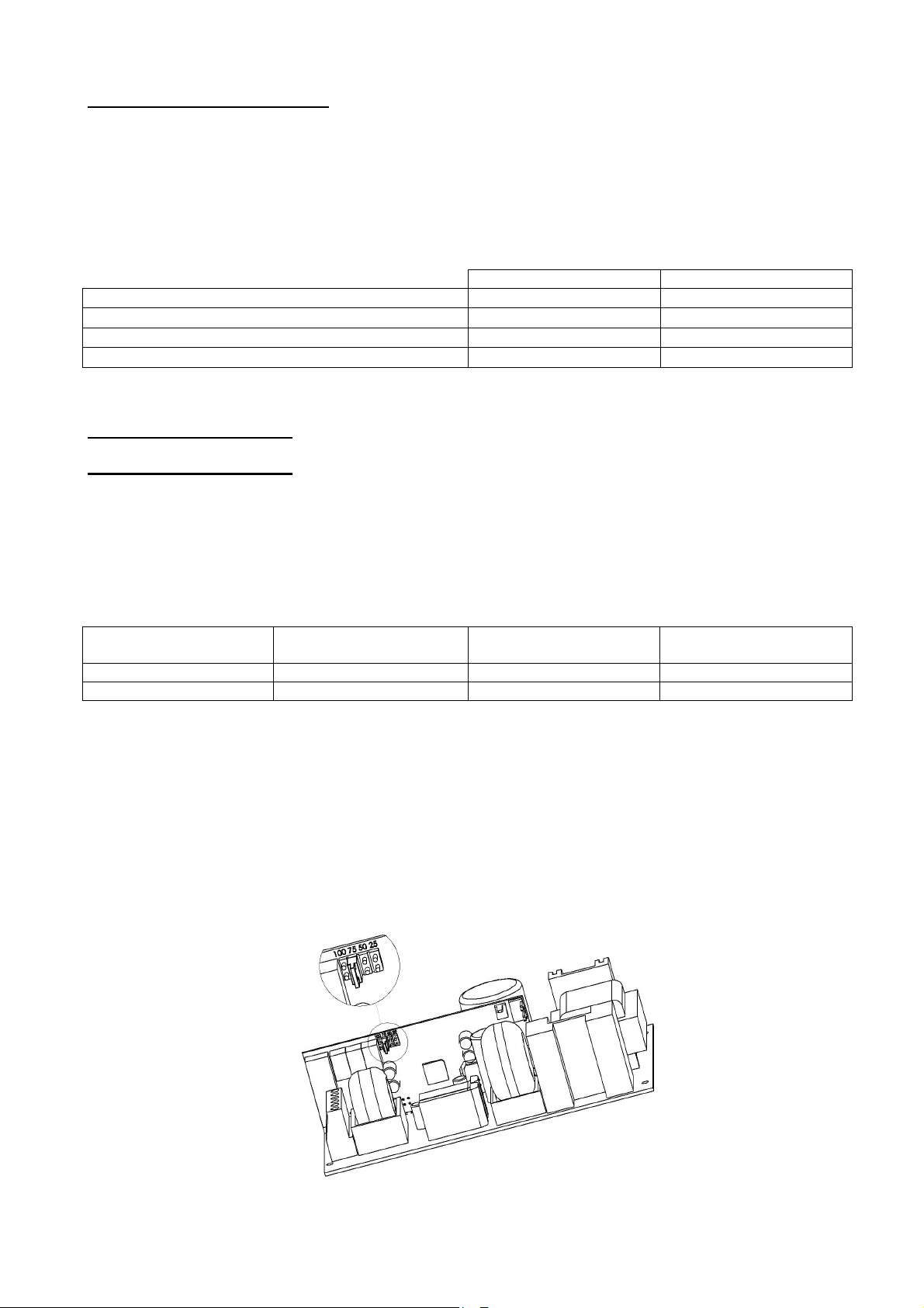
The battery charge current can be set to 25 %, 50 %, 75 % of the rated current (In) using a
configuration jumper on daughterboard positions ‘25’, ‘50’, ‘75’.
compensation
out
limitation
/
Daughterboard jumper
28
Page 29

Battery low voltage cut-out:
The cut-out threshold is 1.8 V/cell
The element causing the cut-out will be in the + position.
6 Maintenance
Maintenance
MaintenanceMaintenance
In order to ensure maximal and durable service, we strongly recommend that your product be maintained
clean and ensure that it is installed in a dry and ventilated location. We shall in no case be liable for damages
associated with improper use or incorrect maintenance of the equipment.
WARNING
Replacing the original battery with a battery of incorrect type may result in an explosion hazard.
Used batteries must be disposed of in compliance with recycling requirements.
±3 %.
7 Fu
Fuse protections
se protections
FuFu
se protectionsse protections
7.1 24 V versions
24 V
2 A
F1 (mains): rating
breaking capacity - size
F7, F8 (load):
rating - type - size
FBat (battery):
rating - type - size
3.15 A Time lag
5x20 - 1500 A
3.15 A Time lag
7.2 48 V versions
48 V
2 A
F1 (mains): rating
breaking capacity - size
F7, F8 (load):
rating - type - size
FBat (battery):
rating - type - size
3.15 A Time lag
Fuse with automatic
24 V
3 A
5x20
Fuse with automatic reset 16 A gG
2 A Time lag
5x20 - 1500 A
5x20
reset
24 V
4 A
2 A Time lag
5x20 - 1500 A
6.3 A Time lag
48 V
3 A
24 V
6 A
5x20
48 V
4 A
6.3 A Time lag
5x20 - 1500 A
6.3 A Time lag
5x20
12.5 A Time lag
5x20
24 V
8 A
6.3 A Time lag
5x20 - 1500 A
12.5 A Time lag
5x20
10.3x38
48 V
6 A
24 V
12 A
48 V
8 A
8 A Time lag
5x20 - 1500 A
12.5 A Time lag
20 A Time lag
24 V
16 A
8 A Time lag
5x20 - 1500 A
25 A gG
10.3x38
32 A gG
10.3x38
5x20
10.3x38
24 V
24 A
48 V
12 A
29
Page 30

8 Troubleshooting procedure
Troubleshooting procedure
Troubleshooting procedureTroubleshooting procedure
If the AES does not deliver voltage
• Check mains presence on the mains terminal strip
• Check the fuses
• Check the voltage value on terminals load1 and/or load2 = floating voltage (see 1.3.2)
• The voltage on the battery cables must be identical to that of the load
• Check that each 12 Vdc battery has a voltage greater than or equal to 11.5 Vdc
• Repeat the measurement after having disconnected the load and the battery
• Recheck the signalling of the indicator lights (see chapter 5, AES Operation)
• If all the steps are validated, check the compatibility of your load
If the battery does not take over after a mains fault
• Check the voltage on the battery terminals
• Check the battery fuse
• Check the voltage on terminals load1 and/or load2
If the indicator lights are not illuminated
• Check mains presence on the mains terminal strip
• Check the battery connection (and the battery fuse)
• Check that the wire ribbon is properly connected
• Check the voltage on terminals load1 and/or load2
For additional technical assistance, contact the SLAT hotline
For return requests, visit our website
http://www.slat.fr/formulaireRMA.php
or contact SLAT After-Sales Service to obtain an RMA (Return Material Authorisation) number.
Returns are not accepted without an RMA number.
+ 33 (0) 4 78 66 63 70
30
Page 31

NOTICE D'UTILISATION P 1
BEDIENUNGSANLEITUNG S 11
OPERATING INSTRUCTIONS P 21
GEBRUIKSHANDLEIDING P 31
MANUAL DE USUARIO
P 41
GEBRUIKSHANDLEIDING
AES
50W tot 600W
31
Page 32

Inhoudsopgave
1 Algemene informatie .............................................................................................. 34
1.1 Schakelschema .............................................................................................................................. 34
1.2 Omgevingspecificaties .................................................................................................................... 34
1.3 Elektrische in- en uitgangspecificaties ........................................................................................... 34
2 Uw apparaat Installeren ......................................................................................... 35
2.1 Bevestigingselementen en afmetingen van de kasten (afm.: LXHXD mm) ................................... 35
2.2 Accu's ............................................................................................................................................. 36
3 Aansluitingen ......................................................................................................... 36
3.1 Aansluitschema .............................................................................................................................. 36
3.2 Maximum kabeldikte aansluitingen ................................................................................................ 37
4 Ingebruikneming .................................................................................................... 37
5 Bediening van de AES ........................................................................................... 37
5.1 Alarmsignalen ................................................................................................................................. 37
5.2 Overzicht van verkrijgbare accessoires .......................................................................................... 38
6 Onderhoud .............................................................................................................. 39
7 Zekeringen .............................................................................................................. 39
7.1 Versies 24V .................................................................................................................................... 39
7.2 Versies 48V .................................................................................................................................... 40
8 Storingen verhelpen ............................................................................................... 40
32
Page 33
Gefeliciteerd,
U hebt een veilige elektrische voedingseenheid van het merk SLAT gekocht en wij danken u hiervoor.
In deze handleiding vindt u alle instructies die u nodig heeft voor het installeren, in gebruik nemen en onderhouden
van dit apparaat.
Wij raden u aan om de instructies aandachtig te volgen voor een goede werking van het apparaat.
Goede installatie.
Veiligheidsvoorschriften
Dit apparaat is bestemd om te worden aangesloten op een netspanning van 230V.
Om elektrische schokken te voorkomen, moeten alle WERKZAAMHEDEN SPANNINGSVRIJ worden verricht
(tweepolige differentiaaluitschakelaar stroomopwaarts is open)
Werkzaamheden onder spanning zijn uitsluitend geautoriseerd voor exploitaties waar uitschakelen onmogelijk is. De
werkzaamheden mogen uitsluitend worden uitgevoerd door bevoegd personeel.
Normen, richtlijnen voor milieubescherming en volksgezondheid
Al onze producten van de SONaes gamma voldoen aan de LVD en EMC-richtlijnen (immuniteit en emissie). Zij
voldoen aan de normen:
• EN 60950-1 (2006) + A11 (2009) + A1 (2010) + A12 (2011) + A2 (2013) (Klasse TBTS)
• EN 61000-6-1(2007), EN 61000-6-2 (2005), EN 61000-6-3 (2007), EN 61000-6-4 (2007) + A1 (2011)
• EN 50130-4 (2011)
• EN 55022 (2006) + A1 (2007) Klasse B
• UL1950 voor componenten.
Zij voldoen bovendien aan de volgende vaknormen:
• EN 54-4 (1997) + A1 (2002) + A2 (2006) : Branddetectiesystemen. Deel 4: installatie voor elektrische voeding
• EN 12101-10 Klasse A (2005): Systemen voor het controleren van rook en hitte Deel 10: installatie voor
elektrische voeding.
• NFS 61940 (2000) : Backup-eenheden.
Bepaalde producten (24V) voldoen aan de normen:
• VdS 2541 (1996) : Energieversorgungseinrichtungen Anforderungen und Prüfmethoden.
• VdS 2344 (2012) : Procedure for the testing, approval, certification and conformity assessment of products
and systems for fire protection and security technologies.
Alle DoP nummers en CE-certificaten zijn beschikbaar in BIJLAGE.
Alle certificaat zijn beschikbaar op onze website: http://www.slat.fr/en/certificatsCE.php
SLAT is gecertificeerd volgens ISO 14001 sinds 2008.
SLAT fabriceert al zijn producten volgens de milieunormen ROHS en DEEE.
SLAT recyclet de producten aan het einde van hun levenscyclus in zijn recyclingnetwerk.
Garantie
Onze garantie is drie jaar af fabriek. De garantie is strikt beperkt tot het vergoeden of vervangen (naar onze keuze en
zonder enige schadevergoeding) van de door onze klantenservice als defect aangemerkte onderdelen, na retour in
onze werkplaatsen op kosten van de koper. Wij gaan niet akkoord met vervanging of reparatie van materiaal elders
dan in onze werkplaatsen. Om onze klanten te laten profiteren van de laatste technische verbeteringen behoudt SLAT
het recht voor om de nodige wijzigingen aan te brengen in zijn producten. De accu maakt geen deel uit van de
garantie.
33
Page 34
50W
75W
100W
150W
200W
300W
400W
600W
0.4A
0.5A
0.75A
1A
1.5A
2A 3A 4A
Nominale spanning
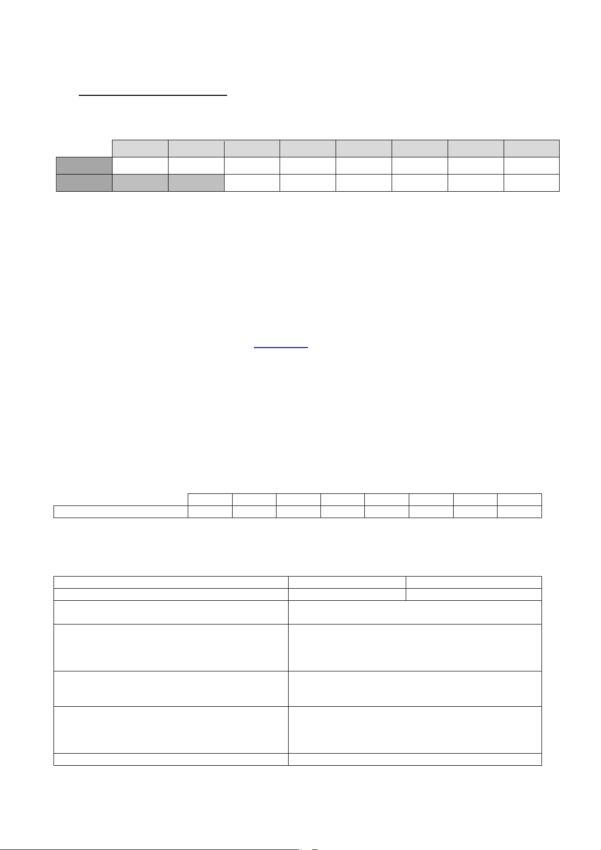
24V 48V
1111 Algemene informatie
Algemene informatie
Algemene informatieAlgemene informatie
1.1 Schakelschema
24V 2A 3A 4A 6A 8A 12A 16A 24A
48V 2A 3A 4A 6A 8A 12A
De aangegeven spanning is de (In) inschakelstroom bij het nominale uitgangsvermogen.
50W 75W 100W 150W 200W 300W 400W 600W
1.2 Omgevingspecificaties
Bedrijfstemperatuur:
- 5°C à + 40°C bij een belasting van 100%
- 5°C à + 50°C bij een belasting van 75%
- 5°C à + 50°C bij een belasting van 100% en voor 50 tot 100W
Opslagtemperatuur: -25 tot +85°C.
Relatieve vochtigheid: 20 tot 95%.
Warmtecapaciteit: Raadpleeg onze website www.slat.fr
De klasse van milieu: 1 (volgens EN 12101-10)
1.3 Elektrische in- en uitgangspecificaties
1.3.1 ingaande netspanning
- Eenfasespanning 195V tot 264V.
- frequentie: 47 tot 63Hz.
- klasse I.
- sterpuntsschakelingen TT, TN, IT.
Primaire stroom @ 195V
Stroomopwaarts te monteren differentiaaluitschakelaar: D curve
1.3.2 Uitgang
Drijvende spanning bij halve belasting en bij 25°C 27.2V
De versie AES kan zonder netspanning
functioneren
De uitgangsstroom In max kan voor één uitgang
worden gebruikt of worden verdeeld over alle
uitgangen.
Maximale uitgangsstroom die continu kan worden
geleverd. (C=accucapaciteit)
Maximale gespecificeerde uitgangsstroom groter
dan I max, die voor een korte periode kan worden
geleverd als de accu niet hoeft te worden geladen
Omschakelingstijd 0s
34
+/-0.5%
54.4V
Imin = 0
In
I max a = In –C/20
I max b = In
+/-0.5%
Page 35
1.3.3 Autonomie
24 V
48 V
Raadpleeg onze website voor de autonomie van de AES en de datumcodes van de accu’s: www.slat.fr
1.3.4 Geautoriseerde accucapaciteiten (Ah/20h – 1.75V/cel)
50W van 7 tot 38Ah van 2.1 tot 12Ah
75W van 7 tot 55Ah van 2.1 tot 12Ah
100W van 7 tot 55Ah van 2.1 tot 12Ah
150W van 7 tot 86Ah van 2.1 tot 12Ah
200W van 7 tot 110Ah van 4 tot 65Ah
300W van 7 tot 166Ah van 4 tot 65Ah
400-600W van 7 tot 225Ah van 4 tot 140Ah
Controleren dat de batterijen zeer in overeenstemming met de normen geldend in de landen zijn waar zij
worden gebruikt
2222 Uw apparaat Installeren
Uw apparaat Installeren
Uw apparaat InstallerenUw apparaat Installeren
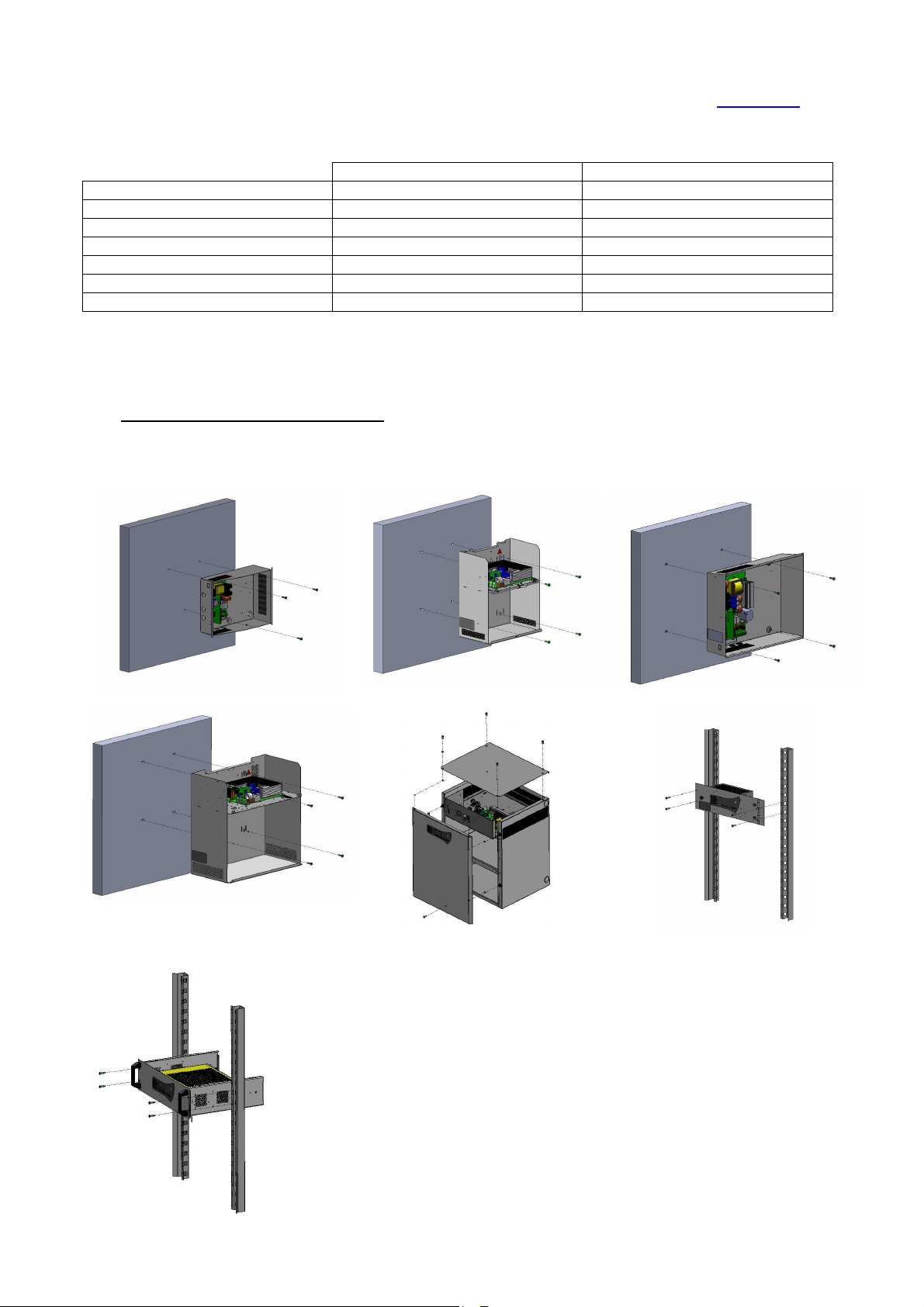
2.1 Bevestigingselementen en afmetingen van de kasten (afm.: LXHXD mm)
C24 - Dim : 322x248x126mm - IP 30
C85 – Dim : 408x408x224mm – IP31
C38 – Dim : 289x350x189mm - IP 31 C48 – Dim : 425x345x120mm - IP30
C180 – Dim : 505x610x430mm – IP31
RackF3U – Dim : 482x133x110mm –
IP30
Rack 3U – Dim : 483x132x358mm – IP30
35
Page 36
2.2 Accu's
Het inbouw- en kabelschema van de accu's vindt u in het bij het product meegeleverd pakket (behalve rack
en F3U versies).
De sonde van de accutemperatuur moet zo dicht mogelijk bij de accu worden geïnstalleerd.
3333 Aansluitingen
Aansluitingen
AansluitingenAansluitingen
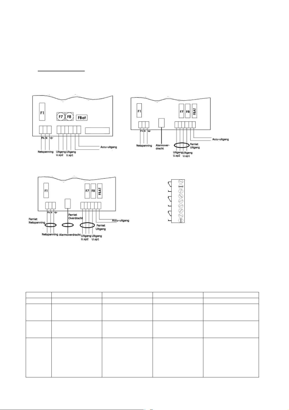
3.1 Aansluitschema
Kabels 50-75W Kabels 100-300W
NC
NO
NC
NO
NC
NO
1
Netspa nn ing
2
3
4
5
6
7
8
9
NC : N o r m a lly C l ose d
NO : N o r m a l ly O p e n e d
Accu
Uitgang
Kabels 400- 600W Kabels alarmoverdracht
* Met de bij de producten meegeleverde klemband bevestigt u het netsnoer op de klemmenstrook voor de
netspanning.
Let op, maak gebruik van de hiervoor bestemde openingen in de kast. Maak geen extra openingen
omdat dit storing zou kunnen veroorzaken in het apparaat en omdat de garantie hierdoor vervalt.
Tabel voor het gebruiken van de ferrietkernen
C24-C48 C38-C85 F3U Rack-C180
50-75W Geen Geen Geen -
100-150W
200-300W
400-600W
te monteren
UITGANG
FERRIETKERN
te monteren
UITGANG
FERRIETKERN
FERRIETKERN
NETSPANNING +
OVERDACHTEN
FERRIETKERN +
te monteren
UITGANG
FERRIETKERN
voorgemonteerde
UITGANG
FERRIETKERN
voorgemonteerde
UITGANG
FERRIETKERN
- - FILTER/FERRIETKERN
te monteren
UITGANG
FERRIETKERN
- voorgemonteerde
-
UITGANG
FERRIETKERN
NETSPANNING +
OVERDACHTEN
FERRIETKERN +
voorgemonteerde
UITGANG
FERRIETKERN
36
Page 37
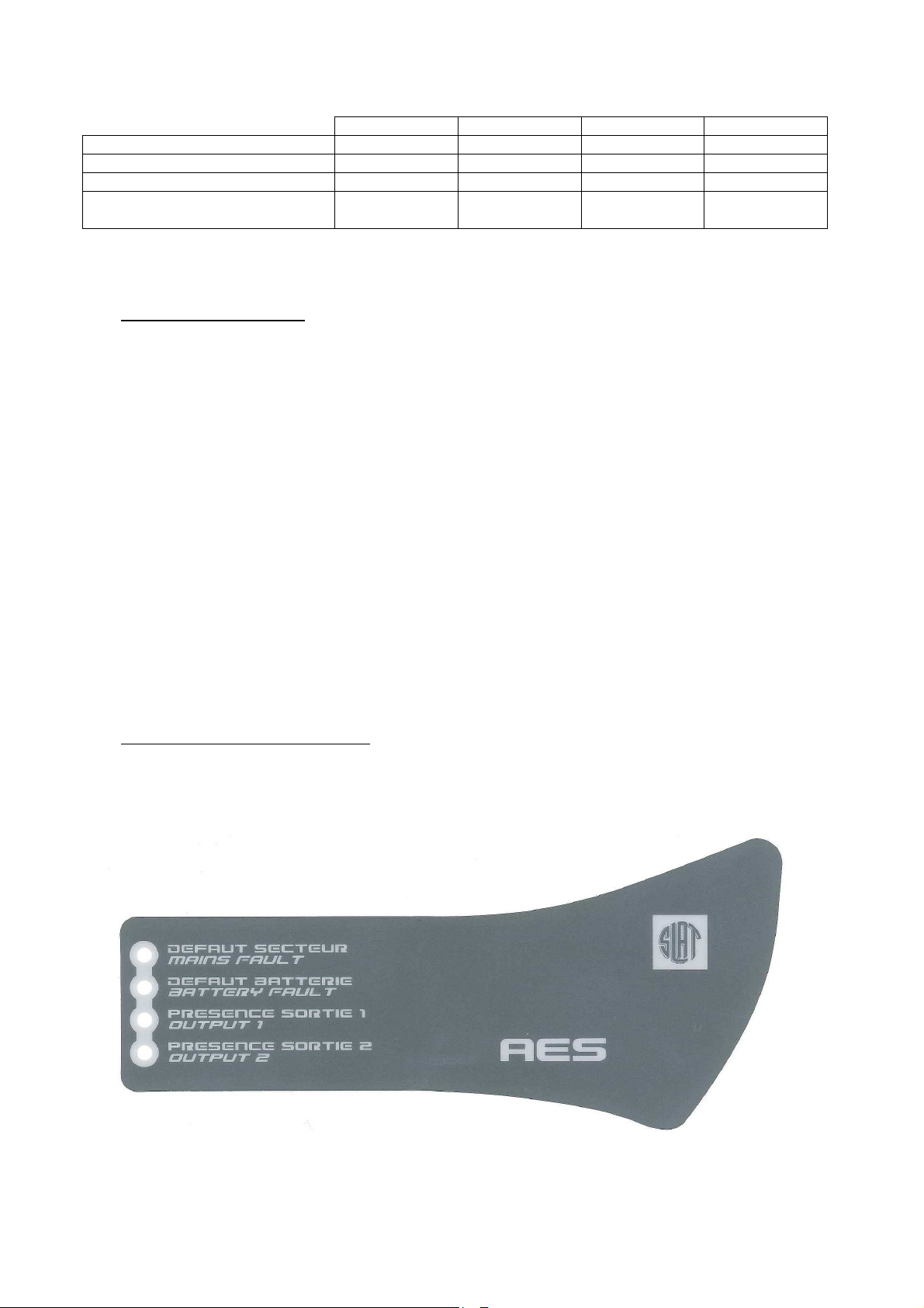
3.2 Maximum kabeldikte aansluitingen
50-75W
100-150W
200-300W
400-600W
Netspanning 2.5mm² 2.5mm² 2.5mm² 2.5mm²
Accu's 2.5mm² 6mm² 6mm² 10mm²
Uitgangsspanning (2 uitgangen) 2.5mm² 6mm² 6mm² 10mm²
Overdracht alarmsignaal
(loskoppelbaar)
4444 Ingebruikneming
Ingebruikneming
Ingebruikneming Ingebruikneming
Open de accuzekering of de zekering voor de kaarten van 50 tot 150W, die zijn voorzien van een
automatische zekering: de accukabels aansluiten op de klemmenstrook maar niet de accuklemmen
aansluiten.
Nadat u alle elektrische aansluitingen (netspanning, uitgangsspanningen en accu's) hebt aangesloten.
1. De differentiaaluitschakelaar van de netspanning stroomopwaarts sluiten.
2. De uitgangspanning van de uitgangsspanning controleren. De LED van de moederkaart wordt
rood.
3. Sluit de accuzekering of sluit de accuklemmen aan voor de kaarten van 50 tot 150W.
4. Controleer de goede werking van de LED op de moederkaart:
o alles ok: groen,
o storing netspanning: oranje,
o storing accu of laadapparaat of geen uitgangsspanning: rood (deze storing is
prioritair ten opzichte van de storing in de netspanning).
5. aardkabel en de vlakbandkabel (indien aanwezig) aansluiten.
6. De kap sluiten.
Uw apparaat is in staat van werking wanneer de 2 groene LEDs voor de netspanning en de accu
branden
1.5mm² 1.5mm² 1.5mm² 1.5mm²
5555 Bediening van de AES
Bediening van de AES
Bediening van de AES Bediening van de AES
5.1 Alarmsignalen
37
Page 38

Netfout (normale bron): wordt lokaal aangegeven door een gele LED en op afstand door een
Accu
-
afschakeling bij
potentiaalvrij contact (failsafe) met timer
Als er geen netspanning is of deze <195V is.
Als de netbeveiliging defect is of ontbreekt.
Als het product defect is
Accufout (backup): wordt lokaal aangegeven door een gele LED en op afstand door een potentiaalvrij
contact (failsafe)
Als de accu ontbreekt:
De accutest verloopt als volgt: elke 30s gedurende de 20 eerste minuten na de
ingebruikneming: elke 15 min na de eerste 20 minuten, Als er een storing is gedetecteerd,
wordt de accu elke 30s getest tot maximaal 20 minuten nadat de storing is verdwenen.
Als de inwendige impedantie te hoog is (test maximaal elke 4 uur bij een geladen accu).
De grenswaarden van de impedantiemeting zijn:
24V 48V
50-75W
100-150W
200-300W
400-600W
650mΩ
410mΩ
164mΩ
82mΩ
+/-10%
+/-10%
1,65Ω
+/-10%
656mΩ
+/-10%
328mΩ
-
+/-10%
+/-10%
+/-10%
Als de accuspanning < 1.8V/cel
+/-3% is.
Aanwezigheid uitgangsspanning 1: lokaal aangegeven door een groene LED
Aanwezigheid uitgangsspanning 2: lokaal aangegeven door een groene LED
De aanwezigheid van uitgangsspanning 1 en 2 worden op afstand aangegeven door een potentiaalvrij
contact (failsafe)
5.2 Overzicht van verkrijgbare accessoires
Gamma Temperatuurcompensatie:
AES 50 - 75W ***/
AES 150 - 600W
***alleen modellen AES 50 en 75W die zijn gecertificeerd volgens VDS zijn voorzien van een sonde.
Temperatuurcompensatie:
Een accuspanningscompensatiesysteem handhaaft dezelfde laadeigenschappen binnen de door
de accufabrikant gestelde specificaties binnen het bereik van de bedrijfstemperatuurlimieten.
Acculaadstroomcontrole:
De acculaadstroom kan worden afgesteld op 25%, 50%, 75% van de nominale inschakelstroom
met behulp van een jumperverbinding met instellingen op de hulpkaart van ‘25’, ‘50’ of ‘75’.
minimale
accuspanning
Acculaadstroomcontrole
/
38
Page 39
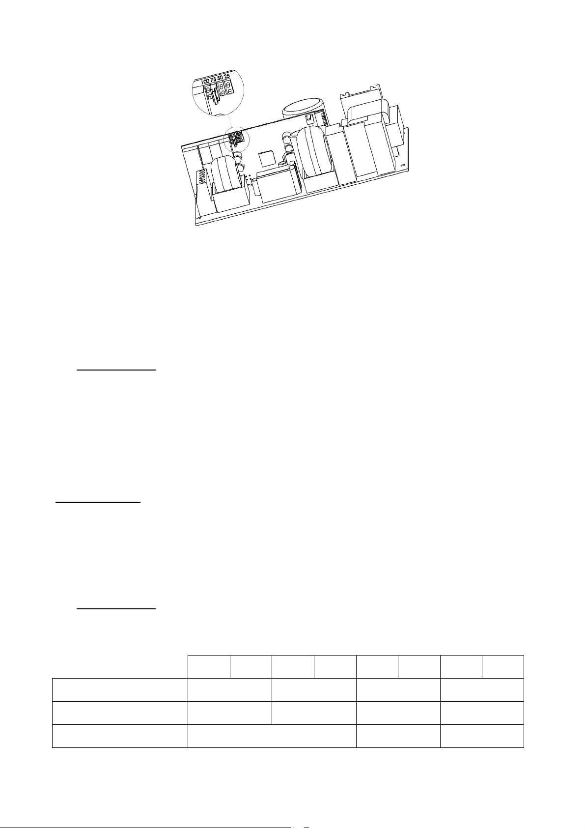
Jumperverbinding op hulpkaart
Accu-afschakeling bij lage accuspanning:
De uitschakelspanning is standaard 1,8V/cel
Het element dat de uitschakeling activeert bevindt zich in de +.
6666 Onderhoud
Onderhoud
OnderhoudOnderhoud
Het apparaat moet in een droge, geventileerde en schone ruimte worden gemonteerd om een maximale
en duurzame levensduur te kunnen bereiken. De fabrikant kan niet aansprakelijk worden gesteld voor
schade veroorzaakt door onjuiste montage, ingebruikneming of onderhoud.
WAARSCHUWING
+/-3%.
Wanneer de originele accu door een niet gelijkwaardig type wordt vervangen, bestaat er kans op een
explosie.
Versleten accu’s moeten worden weggedaan volgens de wettelijke verplichtingen voor recycling.
7777 Zekeringen
Zekeringen
ZekeringenZekeringen
7.1 Versies 24V
24V
2A
F1 (netspanning): kaliber
breeksterkte - maat
F7, F8: (uitgangsspanning):
kaliber - type - maat
FBat (accu):
kaliber - type - maat
5x20 - 1500A
24V
3A
3.15A T
3.15A T
5x20
Automatische zekering 16A gG
24V
4A
5x20 - 1500A
39
24V
6A
2A T
6,3A T
5x20
24V
8A
6,3A T
5x20 - 1500A
12.5A T
5x20
10.3x38
24V
12A
24V
16A
5x20 - 1500A
10.3x38
10.3x38
24V
24A
8A T
25A gG
32A gG
Page 40

7.2 Versies 48V
48V
2A
F1 (netspanning): kaliber
breeksterkte - maat
F7, F8: (uitgangsspanning):
kaliber - type - maat
FBat (accu):
kaliber - type - maat
8888 Storingen verhelpen
Storingen verhelpen
Storingen verhelpen Storingen verhelpen
Als de AES geen spanning levert
• De aanwezigheid van netspanning controleren op de klemmenstrook voor de netspanning
• Controleer de zekeringen
• Controleer de spanning op de aansluitklemmen uitgangsspanning 1en/of uitgangsspanning 2 =
drijvende spanning (zie 1.3.2)
• De spanning op de accukabels moet hetzelfde zijn als de uitgangsspanning
• Controleer of elke accu van 12V gelijkstroom een spanning heeft die gelijk is aan of hoger dan
11,5V gelijkstroom
• Meet nogmaals nadat de uitgangsspanning van de accu is losgekoppeld.
• Controleer de signalen van de lichtdioden opnieuw (zie hoofdstuk 5 Bediening van de AES)
• Als alle stappen zijn bevestigd, controleert u of de uitgangsspanning compatibel is
Automatische zekering 12.5A T
2A T
5x20 - 1500A
3.15A T
5x20
48V
3A
48V
4A
6,3A T
5x20 - 1500A
6,3A T
5x20
5x20
48V
6A
48V
8A
5x20 - 1500A
12.5A T
20A aM
10.3x38
48V
12A
8A T
5x20
Als de accu het voeden niet overneemt na een netspanningsfout
• Controleer de spanning op de accuklemmen
• Controleer de zekering van de accu
• Controleer de spanning op de aansluitklemmen uitgangsspanning 1 en/of uitgangsspanning 2
Als de lichtdioden niet branden
• De aanwezigheid van de netspanning controleren op de klemmenstrook voor de netspanning
• De aansluiting van de accu (en de zekering van de accu) controleren
• Controleer of de vlakbandkabel goed is aangesloten
• Controleer de spanning op de aansluitklemmen uitgangsspanning 1 en/of uitgangsspanning 2
Voor extra technische ondersteuning neemt u contact op met de SLAT hotline
Voor retouraanvragen dient u in te loggen op onze website
http://www.slat.fr/formulaireRMA.php
of kunt u contact opnemen met de SLAT klantenservice om ‘ een RMA nummer (Autorisatie
+ 33 (0) 4 78 66 63 70
voor retour koopwaar) aan te vragen) .
Retourzendingen zonder RMA-nummer zullen niet worden geaccepteerd.
40
Page 41

NOTICE D'UTILISATION P 1
BEDIENUNGSANLEITUNG S 11
OPERATING INSTRUCTIONS P 21
GEBRUIKSHANDLEIDING P 31
MANUAL DE USUARIO
P 41
MANUAL DE USUARIO
AES
de 50 a 600 W
41
Page 42

Índice
1 Información general ............................................................................................... 44
1.1 Tabla de correspondencias ............................................................................................................ 44
1.2 Especificaciones ambientales ........................................................................................................ 44
1.3 Especificaciones eléctricas de entrada y de salida ........................................................................ 44
2 Instalación del equipo ............................................................................................ 45
2.1 Fijación y dimensiones de las cajas (LxAxP en mm) ..................................................................... 45
2.2 Baterías .......................................................................................................................................... 46
3 Conexión ................................................................................................................. 46
3.1 Esquema de conexiones ................................................................................................................ 46
3.2 Secciones máximas de las conexiones .......................................................................................... 47
4 Puesta en funcionamiento ..................................................................................... 47
5 Funcionamiento de la AES .................................................................................... 47
5.1 Alarmas ........................................................................................................................................... 47
5.2 Resumen de los equipos disponibles ............................................................................................. 48
6 Mantenimiento ........................................................................................................ 49
7 Protecciones fusibles ............................................................................................ 49
7.1 Versiones 24 V ............................................................................................................................... 49
7.2 Versiones 48 V ............................................................................................................................... 49
8 Procedimiento de reparación ................................................................................ 50
42
Page 43
Enhorabuena,
Acaba de adquirir una fuente de alimentación segura de la marca SLAT y queremos agradecerle su confianza.
En este manual encontrará todas las indicaciones necesarias para instalar, poner en servicio y realizar el
mantenimiento de este equipo.
Para garantizar el buen funcionamiento del aparato, le recomendamos que las siga al pie de la letra.
Buena instalación.
Normas de seguridad
Este material está diseñado para conectarse a una red eléctrica pública de 230 V.
Para evitar el riesgo de descargas eléctricas, toda INTERVENCIÓN debe realizarse SIN TENSIÓN (disyuntor bipolar
de entrada abierto).
Sólo se permite intervenir con tensión en aquellos casos en que sea imposible desconectar la corriente. Las
intervenciones deberán ser realizadas únicamente por personal cualificado.
Normas, directivas y protección del medio ambiente y de la salud pública
Todos nuestros productos de la gama SONaes cumplen las directivas BT y CEM (inmunidad y emisiones). Asimismo,
son conformes a las normas:
• EN 60950-1 (2006) + A11 (2009) + A1 (2010) + A12 (2011) + A2 (2013) (Clase TBTS)
• EN 61000-6-1(2007), EN 61000-6-2 (2005), EN 61000-6-3 (2007), EN 61000-6-4 (2007) + A1 (2011)
• EN 50130-4 (2011)
• EN 55022 (2006) + A1 (2007) clase B
• UL1950 para los componentes.
También cumplen las siguientes normas profesionales:
• EN 54-4 (1997) + A1 (2002) + A2 (2006) : Sistemas de detección de incendios. Parte 4: Equipos de
suministro de alimentación.
• EN 12101-10 clase A (2005): Sistemas para el control de humo y de calor. Parte 10: Equipos de suministro
de energía.
• NFS 61940 (2000) : Fuentes de alimentación eléctrica de seguridad.
Algunos productos (24V) son conformes a las normas:
• VdS 2541 (1996) : Energieversorgungseinrichtungen Anforderungen und Prüfmethoden.
• VdS 2344 (2012) : Procedure for the testing, approval, certification and conformity assessment of products
and systems for fire protection and security technologies.
Todos los números DoP y los anos de marcaje CE estan indicados en ANEXO.
Todos los certificados estan disponibles nuestra página web: http://www.slat.fr/en/certificatsCE.php
SLAT cuenta con el certificado ISO 14001 desde 2008.
SLAT fabrica todos sus productos de conformidad con las directivas medioambientales RoHS y RAEE.
SLAT garantiza el reciclaje de sus productos al final de su vida útil a través de su cadena de reciclaje.
Garantía
Nuestra garantía es de tres años desde la salida de fábrica. Está estrictamente limitada al reembolso o a la sustitución
(a nuestra elección y sin indemnización de ninguna clase), de las piezas reconocidas como defectuosas por nuestros
servicios, tras su devolución a nuestros talleres por cuenta del comprador. No aceptaremos sustituciones o
reparaciones de material en un lugar distinto a nuestros talleres. Con el fin de que nuestros clientes se beneficien de
los últimos avances técnicos, SLAT se reserva el derecho de efectuar en sus productos todas las modificaciones que
considere necesarias. La batería no está incluida en la garantía.
43
Page 44
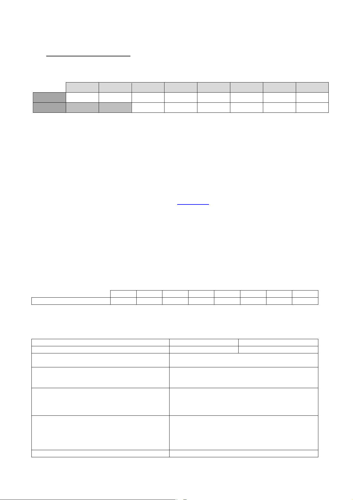
50 W 75 W
100 W 150 W 200 W 300 W 400 W 600 W
0,4 A 0,5 A 0,75 A 1 A 1,5 A 2 A 3 A 4 A
Tensión nominal
24 V 48 V
1111 Información general
Información general
Información generalInformación general
1.1 Tabla de correspondencias
24 V 2 A 3 A 4 A 6 A 8 A 12 A 16 A 24 A
48 V 2 A 3 A 4 A 6 A 8 A 12 A
Las intensidades indicadas son las de la corriente (In) a la potencia nominal de salida.
50 W 75 W 100 W 150 W 200 W 300 W 400 W 600 W
1.2 Especificaciones ambientales
Temperatura de funcionamiento:
-5 °C a +40 °C al 100 % de carga.
-5 °C a +50 °C al 75 % de carga.
-5 °C a +50 °C al 100 % de carga de 50 a 100 W.
Temperatura de almacenamiento: De -25 °C a +85 °C.
Humedad relativa: Del 20 al 95 %.
Capacidad calorífica : consulte nuestra página web: www.slat.fr
Clase de medio ambiente: 1 (según EN 12101-10)
1.3 Especificaciones eléctricas de entrada y de salida
1.3.1 Entrada de la red
- Tensión monofásica: de 195 a 264 V.
- Frecuencia: de 47 a 63 Hz.
- Clase I.
- Regímenes de neutro: TT, TN, IT.
Corriente primaria a 195 V
Disyuntor de entrada a instalar: curva D
1.3.2 Salida
Tensión de flotación a media carga y 25 °C 27,2 V
La versión AES puede funcionar sin corriente de
alimentación.
La corriente de salida In máx. puede utilizarse en
una salida sola o repartida entre todas las salidas.
Corriente de salida máxima especificada que
puede suministrarse de manera continuada. (C =
capacidad de la batería)
Corriente de salida máxima especificada superior
a I máx. a, que puede suministrarse durante un
corto periodo de tiempo durante el cual no se
efectúa la carga de la batería.
Tiempo de interrupción 0s
+/-0,5 %
54,4 V
Imin = 0
I máx. a = In –C/20
I máx. b = In
In
+/-0,5 %
44
Page 45
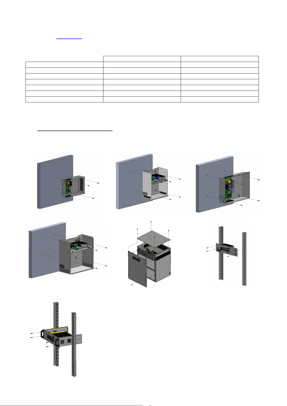
1.3.3 Autonomía
24 V
48 V
Para determinar la autonomía de su AES y entender los códigos de las baterías, consulte nuestra
página web: www.slat.fr
1.3.4 Capacidades autorizadas de las baterías (Ah/20h – 1.75V/elem)
50W 7 - 38Ah 2.1 - 12Ah
75W 7 - 55Ah 2.1 - 12Ah
100W 7 - 55Ah 2.1 - 12Ah
150W 7 - 86Ah 2.1 - 12Ah
200W 7 - 110Ah 4 - 65Ah
300W 7 - 166Ah 4 - 65Ah
400-600W 7 - 225Ah 4 - 140Ah
Comprobar que las baterías se ajustan bien a las normas vigentes en los países donde se utilizan.
2222 Instalación del equipo
Instalación del equipo
Instalación del equipoInstalación del equipo
2.1 Fijación y dimensiones de las cajas (LxAxP en mm)
C24 - Dim : 322x248x126mm - IP 30
C85 – Dim : 408x408x224mm – IP31
C38 – Dim : 289x350x189mm - IP 31 C48 – Dim : 425x345x120mm - IP30
C180 – Dim : 505x610x430mm – IP31
RackF3U – Dim : 482x133x110mm –
IP30
Rack 3U – Dim : 483x132x358mm – IP30
45
Page 46
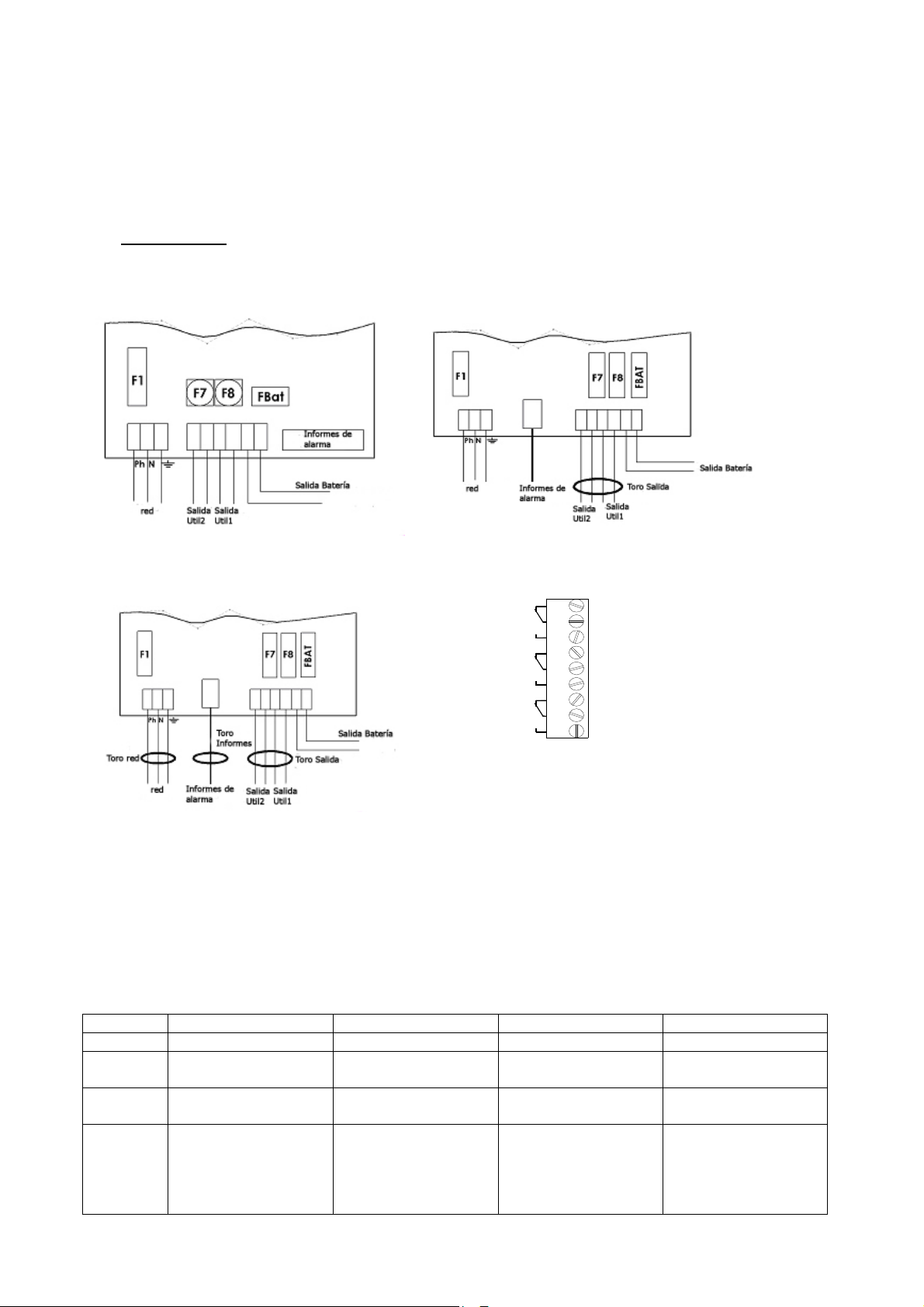
2.2 Baterías
En el kit que se suministra con el producto, encontrará el plano de integración y de cableado de las
baterías (excepto rack y F3U).
La sonda de la temperatura de la batería tiene que situarse lo más cerca posible de la misma.
3333 Conexión
Conexión
ConexiónConexión
3.1 Esquema de conexiones
Cableado 50-75 W Cableado 100-300 W
N C
N O
N C
N O
N C
N O
NC : N o r m a lly C l o sed
NO : N o r m a lly O pe n e d
1
Red
2
3
4
Bateria
5
6
7
Salida
8
9
Cableado 400-600 W Cableado informes de alarma
* La abrazadera suministrada con todos los productos permite sujetar el cable de alimentación general a
nivel del bornero correspondiente.
Atención: deben utilizarse los orificios previstos en la caja. No deben realizarse orificios nuevos,
puesto que podría provocar un funcionamiento anómalo del aparato y quedaría anulada la
garantía.
Tabla de uso de los toros
C24-C48 C38-C85 F3U Rack-C180
50-75 W Ninguno Ninguno Ninguno -
100-
150 W
200-
300 W
400-
600 W
TORO SALIDA a
instalar
TORO SALIDA a
instalar
TORO RED + TORO
NOTIFICACIONES +
TORO SALIDA a
instalar
TORO SALIDA
preinstalado
TORO SALIDA
preinstalado
- - FILTRO/TORO RED
TORO SALIDA a
instalar
- TORO SALIDA
-
preinstalado
+ TORO
NOTIFICACIONES +
TORO SALIDA
preinstalados
46
Page 47
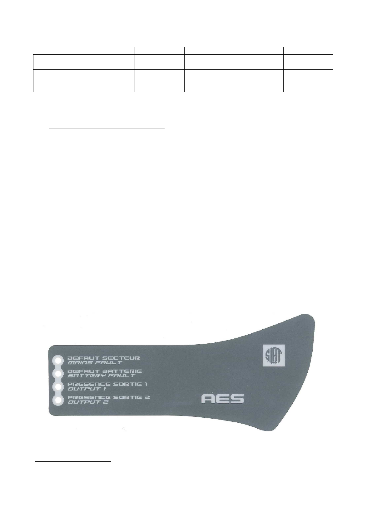
3.2 Secciones máximas de las conexiones
50-75 W 100-150 W 200-300 W 400-600 W
Red 2,5 mm² 2,5 mm² 2,5 mm² 2,5 mm²
Baterías 2,5 mm² 6 mm² 6 mm² 10 mm²
Alimentación (2 salidas) 2,5 mm² 6 mm² 6 mm² 10 mm²
Notificación de alarmas
(desmontable)
4444 Puesta en funcionamiento
Puesta en funcionamiento
Puesta en funcionamiento Puesta en funcionamiento
Abrir el fusible de la batería o, para las tarjetas de 50 a 150 W equipadas con fusible de rearme
automático, conectar los cables de la batería al bornero, pero sin conectar los bornes de la batería.
Después de realizar las conexiones eléctricas (red, alimentaciones y baterías).
1. Cerrar el disyuntor de entrada.
2. Comprobar la tensión de salida de alimentación. El LED de la placa base se pone rojo.
3. Cerrar el fusible de la batería o conectar los bornes de la batería para las tarjetas de 50 a 150 W.
4. En la placa base, comprobar el piloto que indica si el funcionamiento es correcto:
o Todo correcto: verde,
o Fallo red: naranja,
o Fallo en batería o cargador, o ausencia de alimentación: rojo (este fallo tiene
prioridad respecto al fallo de red).
5. Conectar el hilo de tierra y el cable plano (si existe).
6. Cerrar la tapa.
El aparato está en estado de funcionamiento cuando se encienden los 2 LED verdes
correspondientes a las salidas de alimentación.
1,5 mm² 1,5 mm² 1,5 mm² 1,5 mm²
5555 Funcionamiento de la AES
Funcionamiento de la AES
Funcionamiento de la AES Funcionamiento de la AES
5.1 Alarmas
Fallo red (fuente normal): Se indica localmente mediante un LED amarillo y, a distancia, mediante un
contacto seco NC/NO (seguridad positiva) con temporización.
Si no hay suministro eléctrico o es < 195 V.
Si el fusible de red está FS o ausente.
Si el producto está FS.
47
Page 48
Compensación de
Corte tensión batería
Limitación corriente
Fallo batería (fuente de seguridad): Se indica localmente mediante un LED amarillo y, a distancia,
mediante un contacto seco NC/NO (seguridad positiva).
Si no hay batería:
Se realiza un test de la batería de la siguiente manera: cada 30 segundos durante los 20
primeros minutos después de la puesta en marcha; cada 15 minutos después de los 20
primeros minutos. Si se detecta algún fallo, se vuelve a realizar el test cada 30 segundos
hasta que hayan transcurrido 20 minutos desde el momento en que se solucionó el fallo.
Si la impedancia interna es demasiado alta (test cada 4 horas, como máximo, en una batería
cargada).
Los límites de impedancia son:
24 V 48 V
50-75 W
100-150 W
200-300 W
400-600 W
650 mΩ
410 mΩ
164 mΩ
82 mΩ
+/- 10 %
+/- 10 %
+/- 10 %
+/- 10 %
1,65Ω
656 mΩ
328 mΩ
-
+/-10%
+/- 10 %
+/- 10 %
Si tensión batería < 1,8 V/elem
+/-3 %.
Presencia tensión de salida 1 (fuente normal sustitución): Se indica localmente mediante un LED
verde.
Presencia tensión de salida 2 (fuente normal sustitución): Se indica localmente mediante un LED
verde.
Las presencias de tensión de salida 1 y 2 se indican a distancia mediante un contacto seco NC/NO
(seguridad positiva).
5.2 Resumen de los equipos disponibles
Gama
AES 50-75 W ***/
AES 150 a 600 W
***sólo los modelos AES 50 y 75 W con certificado VDS van equipados con una sonda.
Compensación de temperatura:
Un sistema de compensación de la temperatura de la batería permite mantener las características
de carga dentro de los límites especificados por el fabricante de las baterías en todo el rango de
temperaturas de utilización.
Limitación corriente batería:
La corriente de carga de la batería puede ajustarse al 25, 50 o 75 % de la corriente nominal In
con ayuda de un puente de configuración que hay en la tarjeta hija, colocándolo en las
correspondientes posiciones "25", "50" y "75".
temperatura
baja
batería
/
48
Page 49
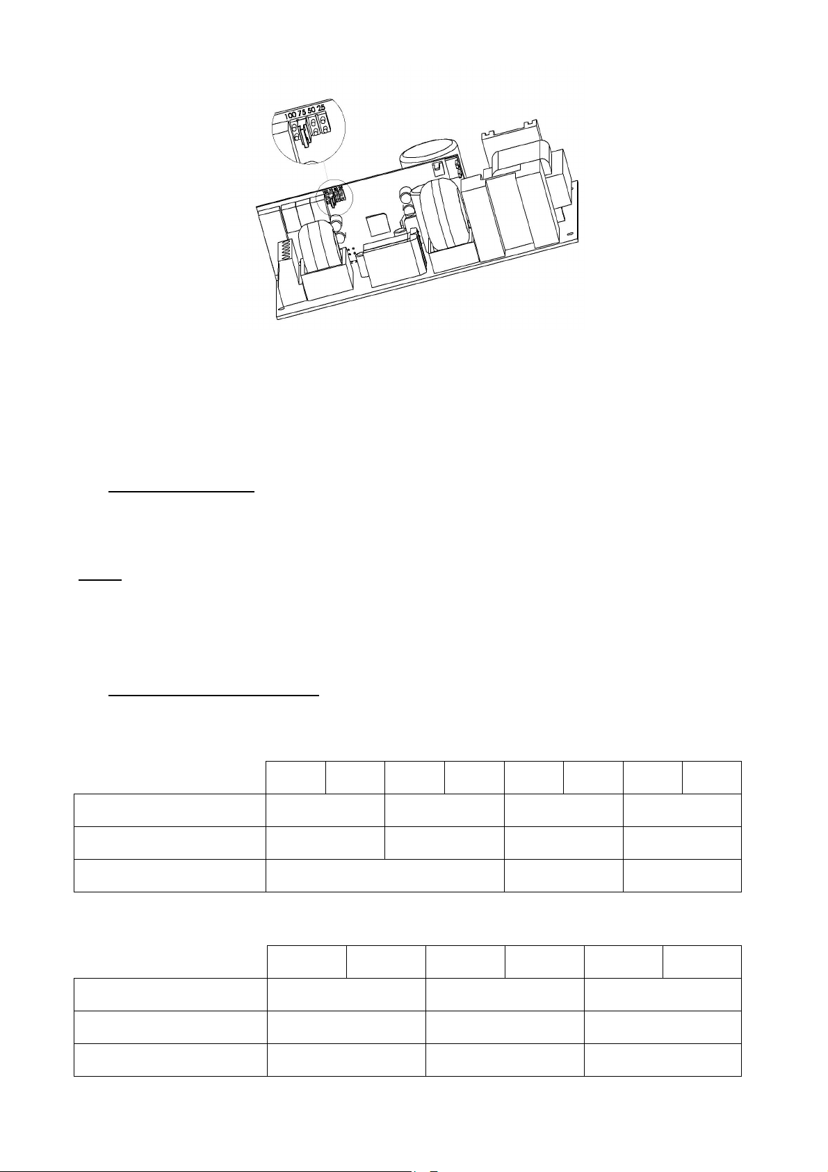
Puente de la tarjeta hija
Corte tensión batería baja:
El umbral de corte es de 1,8 V/elem
El elemento que realiza el corte está situado en el +.
6666 Ma
Mantenimiento
ntenimiento
MaMa
ntenimientontenimiento
Para que su producto le preste un servicio óptimo y duradero, le recomendamos fervientemente
mantenerlo en un estado adecuado de limpieza e instalarlo en un lugar seco y ventilado. En ningún caso
seremos responsables de los daños relacionados con una utilización incorrecta o con un mantenimiento
deficiente de este material.
AVISO
Sustituir la batería original por otra de un tipo inadecuado puede entrañar un riesgo de explosión.
Las baterías usadas deben desecharse siguiendo la normativa sobre reciclaje de materiales.
7777 Protecciones fusibles
Protecciones fusibles
Protecciones fusiblesProtecciones fusibles
+/- 3%.
7.1 Versiones 24 V
24 V
2 A
F1 (red): calibre
capacidad de corte - tamaño
F7, F8 (alimentación):
calibre - tipo - tamaño
FBat (batería):
calibre - tipo - tamaño
3,15 A time lag
5x20 - 1500 A
3,15 A time lag
Fusible de rearme automático 16 A gG
7.2 Versiones 48 V
48 V
2 A
F1 (red): calibre
capacidad de corte - tamaño
F7, F8 (alimentación):
calibre - tipo - tamaño
FBat (batería):
calibre - tipo - tamaño
3,15 A time lag
Fusible de rearme
24 V
3 A
5x20
48 V
3 A
2 A time lag
5x20 - 1500 A
5x20
automático
24 V
4 A
2 A time lag
5x20 - 1500 A
6,3 A time lag
49
24 V
6 A
5x20
48 V
4 A
6,3 A time lag
5x20 - 1500 A
6,3 A time lag
12,5 A time lag
24 V
8 A
6,3 A time lag
5x20 - 1500 A
12,5 A time lag
10,3x38
48 V
6 A
5x20
5x20
5x20
24 V
12 A
48 V
8 A
8 A time lag
5x20 - 1500 A
12,5 A time lag
20 A time lag
24 V
16 A
8 A time lag
5x20 - 1500 A
25 A gG
32 A gG
5x20
10,3x38
24 V
24 A
10,3x38
10,3x38
48 V
12 A
Page 50

8888 Procedimiento de reparación
Procedimiento de reparación
Procedimiento de reparación Procedimiento de reparación
Si la AES no suministra tensión
• Verificar la presencia de red en el bornero de red.
• Comprobar los fusibles.
• Comprobar si el valor de la tensión en los bornes util 1 y/o util 2 = tensión flotación (ver 1.3.2).
• La tensión en los cables de la batería deberá ser idéntica a la de los equipos a alimentar.
• Verificar que cada batería de 12 Vcc presente una tensión igual o superior a 11,5 Vcc.
• Repetir la medición tras haber desconectado los equipos a alimentar y la batería.
• Comprobar de nuevo el funcionamiento de los pilotos (ver capítulo 5: Funcionamiento de la
AES).
• Si todos los puntos anteriores son correctos, verifique la compatibilidad de los equipos a
alimentar.
Si la batería no toma el relevo después de un fallo de la red
• Comprobar la tensión en los bornes de la batería.
• Comprobar el fusible de batería.
• Comprobar la tensión en los bornes util 1 y/o util 2.
Si los pilotos no se encienden
• Comprobar la presencia de red en el bornero de la red.
• Comprobar la conexión de la batería (el fusible de la misma).
• Comprobar que el cable plano esté bien conectado.
• Comprobar la tensión en los bornes util 1 y/o util 2.
Si necesita asistencia técnica adicional, llame a la línea de atención permanente de SLAT
Para devoluciones, consulte nuestro sitio web
http://www.slat.fr/formulaireRMA.php
o póngase en contacto con el servicio posventa de SLAT para solicitar un número de
devolución de mercancía autorizada.
Sin este número, no se aceptará la devolución.
+ 33 (0) 4 78 66 63 70
50
Page 51

ANNEXE / ANHANG / APPENDIX / BIJLAGE / ANEXO
AES
50-75W
AES 100
-
150W
AES 200
-
300W
AES 400
-
600W
Produits
Produkte
Products
Producten
Productos
AES 24V 2A C24 SB 0333-CPR-075229 2008
AES 24V 2A C38 SB 0333-CPR-075231
AES 24V 3A C24 SB 0333-CPR-075230 2008
AES 24V 3A C38 SB 0333-CPR-075373 2008
AES 24V 6A C38 SB 0333-CPR-075180 2007
AES 24V 4A C24 SB 0333-CPR-075185 2008
AES 24V 4A C38 SB 0333-CPR-075189
AES 24V 4A F3U 0333-CPR-075192
AES 24V 6A C24 SB 0333-CPR-075186 2008
AES 24V 6A F3U 0333-CPR-075193 2008
AES 48V 2A C24 SB 0333-CPR-075187
AES 48V 2A C38 SB 0333-CPR-075190 2008
AES 48V 2A F3U 0333-CPR-075194
AES 48V 3A C24 SB 0333-CPR-075188
AES 48V 3A C38 SB 0333-CPR-075191 2008
AES 48V 3A F3U 0333-CPR-075195
AES 24V 8A C48 SB 0333-CPR-075214
AES 24V 12A C48 SB 0333-CPR-075215
AES 24V 8A C85 SB 0333-CPR-075220
AES 24V 12A C85 SB 0333-CPR-075221
AES 48V 4A C85 SB 0333-CPR-075223
AES 48V 6A C85 SB 0333-CPR-075224
AES 48V 4A C48 SB 0333-CPR-075217
AES 48V 6A C48 SB 0333-CPR-075218 2008
AES 24V 8A RACK 0333-CPR-075259 2009
AES 24V 12A RACK 0333-CPR-075260
AES 48V 4A RACK 0333-CPR-075261
AES 48V 6A RACK 0333-CPR-075262
AES 24V 16A C180 SB 0333-CPR-075364
AES 24V 24A C180 SB 0333-CPR-075365
AES 48V 8A C180 SB 0333-CPR-075366
AES 48V 12A C180 SB 0333-CPR-075367
AES 24V 16A RACK 0333-CPR-075368
AES 24V 24A RACK 0333-CPR-075369
AES 48V 8A RACK 0333-CPR-075370
AES 48V 12A RACK 0333-CPR-075371
Numéro de DoP
DoP nummer
DoP number
DoP Nummer
Numero DoP
Années de marquage CE
Jahre der CE markierung
CE marking years
Jaren CE-markering
Anos de marcaje CE
2008
2008
2008
2008
2008
2008
2008
2008
2008
2008
2008
2008
2008
2008
2009
2009
2009
2010
2010
2010
2010
2010
2010
2010
2010
51
Page 52

SLAT
11, Rue Jean Elysée Dupuy BP66
69543 CHAMPAGNE AU MONT D'OR Cedex
France
Tel.: +33 (0)4 78 66 63 60
Fax: +33 (0)4 78 47 54 33
E-mail: [email protected]
http:/www.slat.fr
52
 Loading...