

Page 1

CONTENTS . . . . . . . . . . . . . . . . . . . . . . . . . . . . . . . . . . . .PAGE
Ratings and Dimensions . . . . . . . . . . . . . . . . . . . . . . . . . . . .2–3
Installation Requirements:
Boiler Location . . . . . . . . . . . . . . . . . . . . . . . . . . . . . . . . . . .3
Clearances . . . . . . . . . . . . . . . . . . . . . . . . . . . . . . . . . . . . . .3
Chimney Requirements . . . . . . . . . . . . . . . . . . . . . . . . . . . .3
Air Supply and Venting . . . . . . . . . . . . . . . . . . . . . . . . . . . . .4
Controls and Accessories . . . . . . . . . . . . . . . . . . . . . . . . . . .7
Piping for Steam Boilers . . . . . . . . . . . . . . . . . . . . . . . . . . . .7
Cleaning Piping System . . . . . . . . . . . . . . . . . . . . . . . . . . . .7
Piping for Water Units . . . . . . . . . . . . . . . . . . . . . . . . . . . . . .7
Piping for Tankless Heater . . . . . . . . . . . . . . . . . . . . . . . . . .8
Installing Burner . . . . . . . . . . . . . . . . . . . . . . . . . . . . . . . . . .8
Oil Supply Piping . . . . . . . . . . . . . . . . . . . . . . . . . . . . . . . . .8
Wiring the Boiler . . . . . . . . . . . . . . . . . . . . . . . . . . . . . . . . . .8
Vent Piping and Draft Regulator . . . . . . . . . . . . . . . . . . . . . .9
Operating Instructions:
Precautions Before Starting . . . . . . . . . . . . . . . . . . . . . . . . .9
Start-up . . . . . . . . . . . . . . . . . . . . . . . . . . . . . . . . . . . . . . . . .9
Cleaning and Filling New Water Boiler . . . . . . . . . . . . . .9–10
Blowing Off a Steam Boiler . . . . . . . . . . . . . . . . . . . . . . . . .10
Cleaning and Filling New Steam Boiler . . . . . . . . . . . . . . .10
Low Water Cut-off Check-out . . . . . . . . . . . . . . . . . . . . . . .11
Pressure Control Check-out . . . . . . . . . . . . . . . . . . . . . . . .11
Replacement of Steam Boiler . . . . . . . . . . . . . . . . . . . . . . .11
Burner Data . . . . . . . . . . . . . . . . . . . . . . . . . . . . . . . . . .12,13,14
Care and Maintenance:
Extended Shutdown . . . . . . . . . . . . . . . . . . . . . . . . . . . . . .14
Freezing Protection . . . . . . . . . . . . . . . . . . . . . . . . . . . . . . .14
Oil Burner . . . . . . . . . . . . . . . . . . . . . . . . . . . . . . . . . . . . . .14
General Maintenance . . . . . . . . . . . . . . . . . . . . . . . . . . . . .15
Appendix A . . . . . . . . . . . . . . . . . . . . . . . . . . . . . . . . . . . . . . .15
Appendix
B, C & D . . . . . . . . . . . . . . . . . . . . . . . . . . . . . . . . . .16
SAFETY WARNING:
KEEP BOILER AREA CLEAR AND FREE FROM COMBUSTIBLE MATERIALS, GASOLINE AND OTHER FLAMMABLE VAPORS AND LIQUIDS. FAILURE TO ADHERE TO
ABOVE SAFETY WARNING, MAY RESULT IN PERSONAL
INJURY OR DEATH AND PROPERTY DAMAGE.
Printed in Canada 0906 Publication No. TR-40
Part No. 43-2764 Revision E
INSTALLATION AND OPERATING INSTRUCTIONS
OIL-FIRED WATER AND STEAM BOILERS/NO. 2 OIL
INTREPID
IMPORTANT: The installation of this equipment must conform
to the requirements of the authority having jurisdiction or, in
the absence of such requirements, to the Installation of Oil
Burning Equipment, CSA B139. The installation must also
conform to the additional requirements in this Slant/Fin
Instruction Manual. Where there is any difference, the more
stringent requirement shall govern.
Do not use gasoline crankcase drainings or any oil containing gasoline.
Never burn garbage or paper in this unit, and never leave
combustible material around it.
THIS MANUAL MUST BE LEFT WITH OWNER AND
SHOULD BE HUNG ON OR ADJACENT TO THE BOILER
FOR REFERENCE.
IMPORTANT: This boiler must be installed, serviced and
repaired by a trained, experienced, service technician,
licensed for the installation and servicing of oil burning hot
water heating system equipment or otherwise qualified by
the authorities having jurisdiction over the installation.
Heating Contractor
Address
Phone Number
Boiler Model Number
Boiler Serial Number
Installation Date
Page 2
354
381
354
–
104
–
306
331
90
97
266
–
78
–
1108
–
103
–
251
272
298
327
255
–
298
–
75
–
87
–
223
237
259
284
65
69
76
83
191
–
224
–
56
–
66
–
796
–
933
–
74
–
87
–
TR-20
TR-30
TR-40
TR-50
TR-60
TR-70
292
378
464
549
635
721
11-1/2
14-7/8
18-1/4
21-5/8
25
28-3/8
210
255
298
341
383
426
8-9/32
10-1/32
11-23/32
13-13/32
15-3/32
16-25/32
152¶
152¶
178
203
203
229
¶6¶
¶6¶
7
8
8
9
38
38
38
38
38
–
1-1/2
1-1/2
1-1/2
1-1/2
1-1/2
–
616
702
787
873
959
1045
24-1/4
27-5/8
31
34-3/8
37-3/4
41-1/8
Boiler Model Boiler Length “A”
mm in
Front to Flue “B”
mm in
Flue Diameter “C”
mm in
Circulator Flange
mm in
Overall Length “E”
mm in
2 TR Series
Note: Standard working pressure 207 kPa (30 psi) water,
103 kPa (15 psi) steam.
* ADD SUFFIX
X —Denotes no circulator and no thermostat
P —Packaged water boiler
PT —Packaged water boiler with tankless heater
PZ —Packaged steam boiler less tankless heater
PZT —Packaged steam boiler with tankless heater
§ Tankless heater rating based on intermittent draw.
§§ Nominal clay tile liner dimensions.
** For forced hot water heating systems where the
boiler and all piping are located within the area to
be heated, the boiler may be selected on the
basis of gross output capacity. The net output ratings shown are based on an allowance for piping
and pickup of 1.15 (water) or 1.33 (steam). Gross
output is divided by the allowance to obtain net
rating. The manufacturer should be consulted
before selecting a boiler for unusual piping and
pickup requirements such as intermittent system
operation, extensive piping, etc.
Note: m
2
of steam is equal to net output (W)
divided by 757 W (square feet of steam is equal
to net output (BTU) divided by 240 BTUs)
† Ratings apply to the use of light oil at 11,000 W/L
(140,000 Btu per gallon), and apply only when
burner models listed on pages 15–17 of this manual are used, and are properly adjusted to produce 13% CO
2
.
¶ TR-20 Collar is oblong, will fit 152 mm (6") diame-
ter nominal connector.
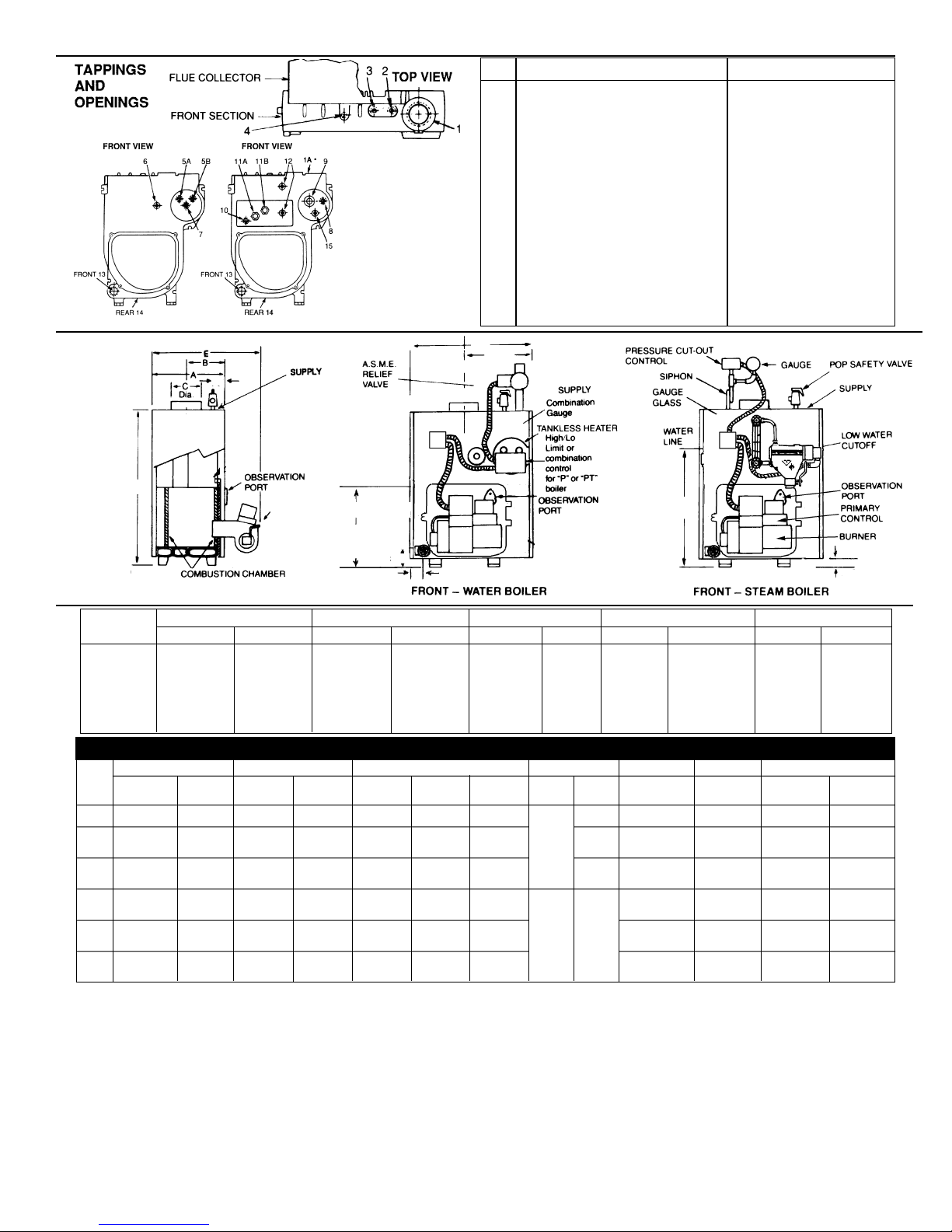
Tapping
Location Steam Boiler Water Boiler
1 76 mm (3”) supply 38 mm (1-1/2”) supply
1A 51 mm (2”) supply on rear section —
2 second 6 mm (1/4”) siphon & pressure 19 mm (3/4”) air vent or expansion tank
cut-out if required
3 19 mm (3/4”) steam safety valve 19 mm (3/4”) water relief valve
4 6 mm (1/4”) siphon, pressure gauge & —
pressure cut-out
5A — 13 mm (1/2”) tankless inlet
5B — 13 mm (1/2”) tankless inlet
6 — 6 mm (1/4”) pressure temp. gauge
7 — 13 mm (1/2”) high limit, hi/lo or
combination control
8 19 mm (3/4”) alternate electronic low
water cut-off
9 38 mm (1-1/2”) skimmer tapping —
10 13 mm (1/2”) low limit for tankless —
11A 13 mm (1/2”) tankless inlet —
11B 13 mm (1/2”) tankless outlet —
12 13 mm (1/2”) steam gauge glass & 67 LWCO —
13 38 mm (1-1/2”) bushed to 19 mm (3/4”) for drain cock 38 mm (1-1/2”) return &
19 mm (3/4”) drain cock
14 38 mm (1-1/2”) condensate return 38 mm (1-1/2”) alternate return
15 3/4” NPT zone tapping —
102mm
(14”)
810 mm (31-7/8")
445 mm (17-1/2")
32 mm (1-1/4")
95 mm (3-3/4")
635 mm
(25")
372 mm
(14-5/8")
648 mm
(25-1/2")
44 mm
(1-3/4")
DRAIN COCK
(Alternate 38 mm
(1-1/2") Tapping
for additional
circulator.)
TR-70
In.
TR-30
3.10
3.35
3.26
3.52
434
469
127
137
104
112
229
229
–
–
–
–
5.45
5.70
343
259
5.00
–
315
–
GROSS OUTPUTBoiler
Model
Number
*
OIL INPUT
mL/s USGPH† kW MBH MBH MBH MBH
MBH Sq. Ft.
Nom. Rect
×Height§§
in.×in.×ft.
mm×mm×m
mmWater Steam
mL/s mL/sUSGPM USGPM
Round I.D.×
Height
in.×ft.
mm.×m
kW kW
kW
m
2
kW
NET OUTPUT** CHIMNEY SIZE TANKLESS HEATER§
Water
Water*
Water Steam
Steam
Steam
Steam
FLUE SIZEAFUE %
.79
.75
1.15
1.31
1.68
1.89
1.60
1.80
2.10
2.35
2.60
2.85
2.20
2.47
2.73
3.00
1.10
1.25
TR-20
TR-40
TR-50
TR-60
31
105
45
51
66
74
224
252
294
329
364
399
86
96
107
117
154
175
26
90
39
44
57
64
195
218
75
80
87
96
134
151
–
–
39
–
57
–
195
–
134
–
23 79
34
38
50
56
170
190
117
131
30
–
–
–
43
–
146
–
101
–
–
–
39
–
55
–
608
–
421
–
152
–
83.50
5"×15'
127×4.6m
152
152
84.15
–
84.85
83.50
178
178
83.80
–
84.45
83.33
203
203
83.45
–
84.06
–
203
203
–
–
–
–
¶6¶
6
6
7
7
8
8
8
8
9
9
139
2.20
202
214
246
261
3.90
4.15
4.40
4.70
4.90
5.20
277
296
309
328
3.20
3.40
–
–
189
–
221
–
3.50
–
4.00
–
4.50
–
252
–
284
–
3.00
–
RATINGS
89 mm (3-1/2")
LEFT END – WATER & STEAM
Water
Figure 1
Figure 2
Steam
6"×15'
152×4.6m
7"×15'
178×4.6m
10"×15'
254×4.6m
8"×15'
203×4.6m
8" × 12"
× 15'
203 × 305
× 4.6m
8" × 8"
× 15'
203 × 203
× 4.6m
1 1
Page 3

TR Series
3
BOILER LOCATION
Provide a level, solid foundation for the boiler. Location should be near
the chimney so that the Flue Pipe Connector or Breaching to the chimney is short and direct.
A. The foundation must be capable of supporting the weight of
the boiler when filled with water:
B. The TR Series Boiler has full wet base sections which surround
fire-box for maximum heat absorption of burning fuel, and low floor
temperature.
C. If boiler is to be located over buried conduit containing electric wires
or telephone cables, consult local codes or the National Board of
Fire Underwriters for specific requirements.
MINIMUM CLEARANCE
Provide accessibility clearance of 610 mm ( 24") from surfaces requiring
servicing (top and front) and 457 mm (18") on any side requiring passage. The boiler shall be installed with the following MINIMUM clearances from combustible materials:
A. CHIMNEY CONNECTOR-457 mm (18")
B. BACK AND LEFT SIDE–152 mm (6") except as limited by 457 mm
(18") clearance for chimney connector
C. RIGHT SIDE–152 mm (6") except for allowing for Burner door fully
open which requires for:
Beckett Burner–191 mm (7
1
/2")
Riello E Series Burner–267 mm (10
1
/2")
D. FLOOR - the boiler is approved for installation on a combustible
floor, but subject to any local code requirements.
NOTE: As an alternate:
The burner door is removable so that the above service clearances are
not mandatory.
CHIMNEY REQUIREMENTS
A. The chimney must be constructed in accordance with all local appli-
cable codes and the National Board of Fire Underwriters. See boiler
models and rating table shown on page 2 for chimney sizes.
INSTALLATION REQUIREMENTS
Boiler
Size
TR- 20
TR-30
TR-40
TR-50
TR-60
TR-70
kg
200
250
300
355
405
455
lbs
440
550
660
785
895
1000
Approximate Total Weight of Boiler
Assembly, filled with water
84.1
–
83.8
–
83.4
–
In.
TR-30
TR-40
TR-50
GROSS OUTPUT
Boiler
Model
Number
*
OIL INPUT
mL/s† USGPH† kW MBH MBH MBH MBH MBH Sq. Ft. mmWater Steam
mL/s mL/sUSGPM USGPM
Round I.D. ×
Height
in × ft.
mm × m
kW
kW
kW m
2
kW
NET OUTPUT CHIMNEY SIZE TANKLESS HEATER
Water
Water**
Water Steam
Steam
Steam**
Steam
FLUE SIZEAFUE %
RATINGS WITH BECKETT BURNERS
1.15
1.31
1.68
1.89
2.20
2.47
1.10
1.25
1.60
1.80
2.10
2.35
45
51
66
74
86
96
154
175
224
252
294
329
39
44
55
63
72
80
132
149
188
214
246
272
39
–
55
–
72
–
132
–
188
–
246
–
34
38
48
55
63
69
117
131
170
190
223
237
30
–
43
–
56
–
101
–
146
–
191
–
39
–
56
–
74
–
421
–
606
–
796
–
152
152
178
178
203
203
84.8
83.5
84.4
83.3
84.0
–
6
6
7
7
8
8
202
214
246
261
284
296
3.20
3.40
3.90
4.15
4.40
4.70
189
–
221
–
252
–
3.00
–
3.50
–
4.00
–
6"×15'
152×4.6m
8"×15'
203×4.6m
Standard Working Pressure 207 kPa (30 PSI) water, 103 kPa (15 PSI) steam.
All boilers hydrostatically tested—A.S.M.E.
* ADD SUFFIX
X —Denotes no circulator and no thermostat
P —Packaged water boiler has tankless heater
PT —Packaged water boiler with tankless heater
PZ —Packaged steam boiler less tankless heater
PZT —Packaged steam boiler with tankless heater
§§ Tankless heater rating based on intermittent draw.
† Ratings apply to the use of light oil of 11,000 W/L (140,000 Btu per gallon.)
** The Net ratings shown are based on a piping and pick-up allowance of 1.15 for
water and 1.333 for stream. For installations having unusual piping and pick-up
requirements, additional allowance should be made before selecting the boiler.
Model
TR-30
TR-40
TR-50
kg
217
257
305
lbs.
479
566
673
kg
221
261
309
lbs.
488
575
682
kg
215
254
295
lbs.
473
559
651
kg
224
263
304
lbs.
483
579
671
P PT PZ PZT
Rectangular
I.D. × Height
in. × in × ft.
mm × mm × m
8"×12"×15'
203×305×
4.6m
8"×8"×15'
203×203
×4.6m
7"×15'
178×4.6m
Page 4

4 TR Series
Figure 3.
Barometric Draft
Regulator
Location
PITCH UP
21 mm/m (1/4" per linear foot)
Drill 6 mm (1/4")
HOLE TO
MEASURE
DRAFT, SMOKE,
CO
2
and stack
temperature
PITCH UP
21 mm/m (1/4" per linear foot)
457 mm
(18")
MINIMUM
229 mm (9")
DRILL 6 MM (1/4")
HOLE TO
MEASURE DRAFT,
SMOKE, CO
2
AND
STACK
TEMPERATURE
MAINTAIN 0.5
MM (0.02")
W.C. DRAFT
(OVER-FIRE)
MAINTAIN 0.5
MM (0.02")
W.C. DRAFT
(OVER-FIRE)
BAROMETRIC DRAFT REGULATOR
INSTALLED ON HORIZONTAL CONNECTION
BAROMETRIC DRAFT REGULATOR
INSTALLED ON VERTICAL RISE
229 mm (9")
457 mm
(18")
MINIMUM
B. Check chimney condition.
Existing chimneys and stacks may have deteriorated; without
repairs their use would be hazardous. Before connecting to an
old chimney or stack:
1. Clean it.
2. Inspect it thoroughly.
3. Remove obstructions.
4. Replace worn sections of metal stacks.
5. Seal bad masonry joints.
6. Repair damaged linings.
C. Where more than one appliance vents into a common chimney,
the area of the common Breaching should at least equal the
area of the largest appliance flue plus 50% of the additional flue
areas.
D. Breaching area must not be reduced at connection into chim-
ney. Breaching must be inserted into, but not beyond, inside of
chimney liner.
E. Chimney height shall extend at least 1 m (3 feet) above where it
passes through the roof of the building, and at least 0.5 m (2
feet) above any ridge within 3 m (10 feet) of the chimney.
F. The use of a vent cap, where permitted by code, gives addition-
al protection against adverse wind conditions and precipitation.
G. Flue Connection: Connect flue pipe between top of boiler and
chimney. Horizontal sections of flue pipe must be pitched
upward to the chimney at least 21 mm/m (
1
/4" per foot). Flue
must be inserted into, but not extend beyond, the inside wall of
the chimney flue. Install draft regulator in flue pipe, as shown in
figure 3.
AIR SUPPLY AND VENTILATION
(see CSA B139, latest edition, Section 7)
Sufficient air for combustion and ventilation in the boiler room
must be provided. Failure to do this will result in poor combustion, heavy sooting and health hazards.
BAROMETRIC DRAFT
REGULATOR
BAROMETRIC DRAFT
REGULATOR
Page 5

TR Series
5
Any oil-fired boiler must have a steady draft* and an ample supply of
combustion air at all times during firing. If air supply or chimney
draft* is unreliable, CO
2
and overfire draft* will change unpredictably.
DO NOT vent this boiler to the same chimney flue used by a
fireplace or coal or wood burning furnace or boiler. The draft*
produced by solid fueled devices varies tremendously between
high fire and low fire:
In modern, weather stripped, energy-saving buildings or older
buildings which have been modified similarly, natural infiltration
may not supply enough air for combustion, particularly if other fuel
burning appliances, exhaust fans or draft inducers are competing for
the same air supply. Fireplaces, other solid fuel burning appliances
and exhaust fans consume great quantities of air; if air supply is not
ample, such an appliance will create a downdraft in the oil-fired boiler
flue. This can create a hazardous condition. Flue gases can be
sucked out of the chimney through the vent regulator into the living
space. DO NOT operate this boiler and a solid fuel burning appliance
at the same time, unless the solid fuel burner is provided with its own
outside air supply.
See Table 2, “Provisions for Combustion and Ventilation Air Supply”
for determining need and method of providing air for combustion and
ventilation.
If fly screen must be used over air supply openings, areas calculated
should be doubled; the screen should be inspected and cleaned frequently to maintain free air flow.
Protect air openings against closure by snow, debris, etc. Openings
such as doors or windows, if used, must be locked open.
TABLE 2: Provisions for Combustion and Ventilation Air Supply. See CSA B139, latest edition, section 7, for more detailed
information.
* Draft is negative or suction pressure
Boiler Location Air Supply
2.1 Unconfined space Is there sufficient air for combustion by natural infiltration (see
NOTE (1), “Test...” below)?
2.2 Unconfined space If there in NOT sufficient air for
combustion by natural infiltration
due to tight construction or other
conditions, then it REQUIRES AIR
FROM OUTDOORS. SEE “ACTION
REQUIRED” column at right. See
Notes (1) and (2) below.
2.3 Confined space If there is sufficient air for combustion from within building but it
comes from outside of the
confined space, see “ACTION
REQUIRED” column at right.
See Note (1) below.
2.4 Confined space If there is NOT sufficient air for
combustion due to tight construction or other conditions it
REQUIRES AIR FROM OUTDOORS. SEE “ACTION
REQUIRED” column at right.
See NOTE (2) below.
Action Required
NONE
Provide air from outdoors directly through a permanent outside wall opening or openings with a free open area of not
less than 645 mm
2
/1172W (1 sq. in. per 4000 Btu/hr) of
TOTAL input of ALL fuel burning appliances in the building.
See Note (1) and (3).
The confined space shall be provided with two permanent air
openings, one near the top of the enclosure and one near the
bottom. EACH opening shall have a free air opening of not
less than 645 mm
2
/293 W (1 sq. in. per 1000 Btu/hr.) of
TOTAL input of ALL fuel burning appliances within the enclosure. The two openings shall freely communicate with the
interior areas of the building which in turn would have to have
adequate infiltration of air from outdoors. See Notes (1, 3)
and Figure 3a.
(a) Air from the outdoors shall be provided to the confined
space by two permanent openings, one in or near the top
of the enclosure space and one in or near the bottom.
The openings shall communicate directly, or by means of
ducts, with outdoors or to such spaces (crawl or attic) that
freely communicate with outdoors (See figures 3b, 3c
and 3d).
(b) Where directly communicating with outdoors or by means
of vertical ducts, each opening shall have a free area of
not less than 645 mm
2
/1172 W (1 sq. in. per 4,000 Btu/hr.)
or 5964 mm
2
/litre/hr (35 sq. in. per gal. per hr.) of total
input rating of all appliances in the enclosure. If horizontal
ducts are used, each opening shall have a free area of not
less than 645 mm
2
/586 W (1 sq. in. per 2,000 Btu/hr.) or
11928 mm
2
/Litre/hr ((70 sq. in. per gal. per hr.) of total
input of all appliances in the confined space. See Figures
3b, 3c and 3d.
(1) Test for sufficient air for combustion by infiltration by running this boiler for 30 minutes under all of the following conditions and at the same time: a) all doors,
windows and other like openings must be closed, b) all fuel burning appliances should be FIRING, c) all exhaust fans and clothes dryers turned ON. At the
above conditions the CO
2
, smoke and draft readings must be normal. (CO2between 11% and 13%, smoke between ZERO and a TRACE, draft between 0.5 mm
(.02") W.C. and 1.0 mm (.04") W.C. negative pressure.)
(2) Aside from tight construction, some of the conditions that steal air for combustion from a boiler are other fuel burning appliances, exhaust fans and clothes dry-
ers.
(3) Generally, louvers made of wood have a free open area of 20% and those made of metal have a 60% to 70% free open area. Screens also reduce the open area
of the louvers.
Page 6

6 TR Series
Figure 3a.
Appliances located in confined spaces. Air from
inside the building. See Table 2 (2.3).
Figure 3b.
Appliances located in confined spaces. Air from outdoors. See Table 2 (2.4).
Figure 3c.
Appliances located in confined spaces. Air from outdoors through ventilated attic. See Table 2 (2.4).
Figure 3d.
Appliances located in confined spaces. All air from
outdoors through ventilated crawl space and outlet
air to ventilated attic. See Table 2 (2.4).
305 mm
(12 in.)
max
.
CHIMNEY
OPENINGS
127 mm
(5 in.)
max.
305 mm
(12 in.) max.
152 mm
(6 in.) max
.
BOILER
BOILER
BOILER
BOILER
CHIMNEY
OUTLET AIR DUCT
INLET AIR DUCT
CHIMNEY
VENTILATION LOUVERS
(EACH END OF ATTIC)
INLET AIR DUCT
(ENDS 305 mm
(1 FT.) ABOVE
FLOOR.)
OUTLET
AIR
CHIMNEY
VENTILATION LOUVERS
(EACH END OF ATTIC.)
OUTLET
AIR
INLET AIR
VENTILATION LOUVERS
FOR UNHEATED CRAWL SPACE
Page 7

TR Series
7
INSTALLING CONTROLS AND
ACCESSORIES ON BOILER UNITS
Notes: Jacket must be installed on boiler units prior to installation
of trim.
I. STEAM BOILER TRIM, see page 2 for tapping locations, and
figure 4 for illustration of steam boiler.
A. Steam pressure gauge and pressure cut-out, install in tapping
no. 4, figure 4.
B. Gauge glass set — use tapping no. 12.
C. Pop safety valve — use tapping no. 3, piped full size to boiler; or
pipe full size into a valveless steam header.
D. Combustion safety control — mounted on burner.
II. WATER BOILER TRIM, see page 2 for tapping locations, and fig-
ures 1 and 2 for illustration of water boiler.
A. Pressure- temperature - altitude gauge — use tapping no. 6.
B. High temperature limit — use tapping no. 7.
C. Operating control (if used) — use tapping no. 7.
D. Water relief valve — use tapping no. 3, piped full size
to boiler.
E. Automatic air vent or compression tank tappings — if used,
install in tapping no. 2.
F. Combustion safety control — mounted on burner.
G. A low water cut-off may be required by local codes. If the boiler
is installed above the radiation level, a low water cut-off device
must be installed in all instances. Do not install an isolation
valve between the boiler and the low water cut-off.
PIPING
IMPORTANT: Boilers are to be used with closed system. Any
application that uses steam or water from system, causes the
introduction of a frequent supply of fresh water into the boiler. This
will cause damage to the boiler. Use of heat exchangers will prevent
this damage.
PIPING FOR STEAM BOILERS
Provide Header and Hartford Loop as suggested. See figures 4
and 5. Local codes apply.
CLEANING PIPING SYSTEM
A. To clean piping system, open all valves at the heating elements.
After getting up a good head of steam, shut the boiler down and
allow the condensate to return to the boiler. The condensate will
carry the oil film with it. Again blow off the boiler. On extremely
fouled systems, it may require several visits over a few days to clean
the system.
B. When steam only (no water) is released through the hand valve, the
boiler will not surge or flood.
C. See page 10 for complete blowing-off instructions.
PIPING FOR WATER UNITS
NOTE: On knocked-down boiler only, jacket may be installed after
supply and return piping connection, but must be installed prior to
adding trim.
I. CIRCULATING SYSTEM
A. FORCED CIRCULATION hot water heating system: Use the
top tapping as supply tapping, and use the front and/or rear
bottom tappings for the return.
B. A FLOW CONTROL VALVE (See figure 6) will prevent gravity
circulation and usually is required when tankless heater is
installed.
II. AIR CONTROL SYSTEMS
A. DIAPHRAGM-TYPE COMPRESSION TANKS are used to con-
trol system pressure in an AIR ELIMINATING SYSTEM:
an automatic air vent is used to REMOVE air from the system
water. See figure 6. If system pressure needs further control, add
an additional tank or install a larger capacity tank. The automatic
air vent should be installed in the top of the boiler, as in figure 6.
B. CONVENTIONAL COMPRESSION TANKS (non-diaphragm type)
are used to control system pressure in an AIR COLLECTING
SYSTEM. Within the system, after initial start-up and venting, air
is collected in the tank and acts in contact with the water to con-
trol pressure. Air is not vented from this system.
If system pressure needs further control, add another tank in
parallel with the original tank or install a large capacity tank.
Locate the tank at the inlet end of the pump near the boiler.
(See figure 7)
Escape pipes, drain pipes from relief valves, blow down
valves and low water cut-offs must be piped to safe
place for discharge.
NIPPLE 6 mm (1/4") CLOSE
NIPPLE 6 mm (1/4") X 64 mm (21/2")
ELBOW 6 mm (1/4") X 90°
6 mm (1/4") TEE
6 mm (1/4") SYPHON
Boiler A
Size Dim.
TR-50 402 mm (15-27/32")
TR-60 488 mm (19-7/32")
TR-70 574 mm (22-19/32")
Models TR-50 through TR-70
Models TR-30 through TR-40
Figure 5
Page 8

8 TR Series
C. HOT WATER RADIATION VENTING–Manual air vents should be
installed at the top of all "drops"(where piping goes downward).
Air must be vented or purged from all zone lines to permit proper
system heating.
D. PUMP LOCATION–Locating low-head pump(s) on return to boil-
er is only acceptable in residences of one or two stories. (See
figure 6) The pump location shown in figure 7 is required in large,
multi-story building installations, especially when high-head
pumps are used and is also recommended for all applications.
E. A conventional compression tank may be connected to the 19
mm (
3
/4") tapping as shown in figure 7.
IMPORTANT: Hot water heating systems containing high water volume,
such as would occur with cast-iron radiation, require special care with
air elimination. The circulator pump should be located on the boiler
supply pipe and the expansion tank and air scoop should be located
near the pump suction. (See Figure 6, Alternate Pump Location.)
PIPING TANKLESS HEATER (if used)
I. Heater capacities are listed on Page 2.
II. Pipe the built-in tankless heater using the inlet and outlet tappings
indicated on the heater (figure 8).
A. Tempering valve (illustrated, but not furnished) is suggested to
provide more volume of temperate water to kitchen and bath.
B. High temperature water, for dishwasher and laundry, may be
piped direct.
C. A flow control valve should be used to control the rate of flow of
water through the coil, otherwise the heating capacity of the coil
will be exceeded. To insure sufficient hot water, the flow rate
through the coil should be limited to a maximum shown for intermittent draw in the ratings table on page 2.
INSTALLING THE BURNER
See Burner Data, pages 12 to 14, and Burner Manual supplied with
burner. If burner is not mounted as received, mount to boiler, placing
flange over mounting studs. Use gasket between flange and boiler.
Distance between flange and nose of burner (insertion depth) must be
as shown on page 14, (note 3) and page 14 (fig. 12).
OIL SUPPLY PIPING
Install the oil tank or tanks and piping from tank to burner. Follow local
codes and practices, CSA B139 and the instruction sheet attached to
the oil burner pump. A one-pipe system should be used for gravity-fed
fuel systems and for lift systems, where the total lift is less than 2.5 m (8
feet). Where the total lift is greater than 2.5 m (8 feet), a two-pipe system
must be used. In some instances, local codes may require a two-pipe
system for below grade fuel oil tanks. Be sure to set-up the fuel oil
pump for the piping system used; follow the instructions attached to the
pump. Be sure to include a good quality, low pressure drop fuel oil filter
in the supply line from the tank. This is necessary, especially at low fuel
oil flow rates (small nozzle sizes), to prevent nozzle plugging. See
Slant/Fin publication on one-pipe and two-pipe fuel oil systems.
WIRING THE BOILER
A. The wiring diagrams for the burner and boiler are enclosed
separately.
B. 24 volt control wiring should be approved Safety Circuit wire,
protected as needed.
C. Power supply wiring to the burner must be 14 gauge or heavier, as
required, and should have a properly fused disconnect switch. 120
volt wiring to pumps and safety controls must also be 14 gauge or
heavier. Wire must be enclosed in approved conduit.
D. All wiring must be installed in compliance with the National Electric
Code, or any local or insurance codes having jurisdiction.
19 mm (3/4
")
PRESSURE
REDUCING
VALVE
(by others)
Consult local
codes other
valves
requirement
Page 9

TR Series
9
VENT PIPING AND DRAFT REGULATOR
A. Vent pipes must be installed having the same diameter as the boiler
outlet. (See page 2)
B. Vent pipes and Breaching must be pitched upward a minimum of
21 mm/m (
1
/4") per foot.
C. Connect vent pipe to the chimney using as few elbows as possible.
D. Horizontal vent connector into the chimney should not be inserted
beyond the inside wall of the chimney.
E. Install barometric draft regulator on vertical or horizontal Breaching,
near chimney, with hinge horizontal and face vertical. See manufacturer's instructions packed in carton with barometric draft regulator
and page 4.
F. If two or more appliances are used on the same chimney, see
CHIMNEY, page 3 and 4.
G. Make up all joints with minimum air leaks, secure with sheet metal
screws.
PRECAUTIONS BEFORE STARTING OIL BURNER
Make a positive check of A through H before starting burner:
A. Boiler and system are full of water. All air is vented from system.
See below.
B. All wiring is completed.
C. Oil supply is connected to the burner; nozzle is installed correctly;
oil valve is open at tank.
D. Smokepipe is connected to chimney.
E. All combustible materials are cleared away.
F. Combustion air supply is provided. See page 4.
G. Burner settings are adjusted as per pages 12 – 14 and as shown on
boiler jacket.
H. Main cast-iron door on which burner is mounted is bolted shut and
fiberglass rope seal is making good contact.
* Draft is negative or suction pressure.
START-UP (COMBUSTION TEST INSTRUMENTS MUST BE USED)
A. Make sure the boiler is installed and wired properly and is full of
water.
B. Open the observation door (on the front, above the burner).
C. Start the oil burner (see burner instructions for bleeding air from oil,
etc.). IMMEDIATELY, set burner air bands to obtain a bright fire
without smoke or oil stain. Set the DRAFT REGULATOR to obtain
0.5 mm (.02") overfire draft*. Take draft reading through slot in
observation door.
D. Close the observation door. Allow the burner to fire for at least one
hour total firing time, to bake out the volatile binders in the combus-
tion chamber before taking final combustion readings.
E. By alternate adjustment of the barometric draft regulator, the burner
air regulation and head regulation devices (whichever apply), set for
a trace of smoke and as close to 13% CO
2
as you can. Then open
the air bands or shutter (whichever apply) an additional 3 mm (
1
/8").
This should result in zero smoke with NO raw oil on the smoke
paper and a smooth light-off. DO NOT ATTEMPT TO SET FIRE BY
EYE. Flame retention burners may appear efficient and smoke free
from an inefficient 7% up to an overly high 14% CO
2
. However, a
very low CO
2
can also result in poor ignition and raw (unburned) oil
entering the fire box. At very high CO
2
, any slight decrease in air
flow for any reason will cause incomplete combustion, with high
smoke and dry soot formation in the fire box.
F. If smoke reading is satisfactory, but CO
2
can not be increased to a
satisfactory level (12% or better) or overfire draft of 0.5 mm (0.02")
W.C. can not be obtained, check for proper sealing between sections, between burner mounting plate and front section, around
burner blast tube and around flue collector and collar. If seal is not
satisfactory, reseal with furnace putty or silicone with a temperature
rating of at least 204°C (400° F). (All safety precautions indicated on
material package must be followed.)
G. Once burner and draft have been set up, then smoke, CO
2
and
stack temperature should be checked and recorded. If smoke is
greater than trace, review the burner instructions; replace the nozzle
if necessary. Normal smoke to be expected at approximately 13%
CO
2
is zero to a trace.
CLEANING AND FILLING A NEW WATER BOILER
I. BEFORE FILLING WATER BOILER
A. Check burner to be certain it is ready for firing. DO NOT FIRE
into an empty boiler.
B. Be prepared to heat raw water to at least 82°C (180°F). as soon
as it is introduced into the boiler. This procedure will remove
dissolved, corrosive gases.
C. Provide drain line, with valve, from boiler. Use a bottom tapping.
Line and drain must be suitable for handling caustic solution.
II. CLEANING WATER BOILER SYSTEM
A. Prepare a boil-out solution of sodium hydroxide (caustic soda)
or tri-sodium phosphate.
NOTE: Use caution in handling chemicals. Caustic soda is
harmful to skin, eyes and clothing.
1. Proportions: .25 kg (1 lb) of either chemical per 100 L (50
gallons) of system water.
2. Stir chemical in water until dissolved and pour into the
boiler through a top tapping. Replace plug.
B. Fill the entire system with water.
C. Start the burner, using the start-up procedure.
D. Circulate the water through the entire system.
E. Vent the system, including the radiation.
F. Allow boiler water to reach operating temperature, if possible.
G. Continue to circulate the water for a few hours.
H. Shut off the burner.
I. With CAUTION, drain the boiler solution to a safe location. DO
NOT LEAVE SOLUTION SITTING IN SYSTEM OVER 2
HOURS.
J. Wash the water side of the boiler thoroughly using a high pres-
sure water stream. Fill and drain the boiler several times.
III. TREATING WATER FOR CORROSION CONTROL
(This is not scale control)
A. Prepare a solution of sodium chromate.
Proportions: 94cc/100L (6 oz. per 50 gallons) of system water.
B. Stir chemical into water until dissolved and pour into the boiler
through a top tapping. Replace plug.
IV. FILLING AND VENTING THE WATER BOILER
A. Refill the system with fresh water.
B. Bring water temperature to at least 82°C (180°F) promptly.
C. Circulate water through entire system.
D. Vent the system, including the radiation.
E. The boiler is now ready to be put into service or on standby.
F. If brand-name air-control devices are used, venting instructions
furnished with the devices should be followed.
V. SAFETY CHECK FOR CONTROL SYSTEM
High limit control test: Set thermostat high enough for boiler water
temperature to reach high limit control setting. When this temperature is reached, the high limit switch should open, and the burner
should shut off automatically. If the high limit does not operate to
shut off the burner, the high limit or the wiring is faulty. Repair or
replace immediately.
CLEANING AND FILLING A NEW STEAM BOILER
I. BEFORE USING STEAM BOILER
A. Check burner to be certain it is ready for firing. DO NOT FIRE
into an empty boiler.
B. Be prepared to heat raw water to at least 82°C (180°F). as soon
as it is introduced into the boiler. This procedure will remove
dissolved, corrosive gases.
C. Provide drain line, with valve, from boiler. Use a bottom tapping.
Line and drain must be suitable for handling caustic solution.
D. Check for low water cut-off operation, see section below for
check-out.
WARNING: NEVER OPERATE any natural draft* boiler
(TR Series boiler is a natural draft boiler) with zero draft or
overfire pressure: early failure of the burner, nozzle and
chamber is inevitable if you do. Use a draft gauge, and
make sure that overfire draft* is 0.5 mm (.02"), minimum,
during all operating conditions.
OPERATING INSTRUCTIONS
Page 10

10 TR Series
II. CLEAN STEAM BOILER SYSTEM.
A. Fill the boiler to water line indicated on the boiler.
B. Follow start-up procedure for burner and operate the boiler with
steam in the entire system for 2 or 3 days to bring oil and dirt
from the system to the boiler. While system is in operation,
maintain the proper water level in the boiler by slowly adding
water to the boiler.
C. Shut down burner, cool down boiler and drain system.
D. Procedure to dissolve oil and grease in boiler:
1. Fill boiler to proper water line.
2. Prepare a boil-out solution of sodium hydroxide (caustic
soda) and tri-sodium phosphate:
NOTE: Use caution in handling chemicals. Caustic soda is
harmful to skin, eyes and clothing.
(a) Proportions: .25 kg (1 lb.) of each chemical per 100 L (50
gallons) of system water.
(b) Stir chemicals into water until dissolved and pour into the
boiler through a top tapping. Replace plug.
3. Start the burner; boil the water for at least 5 hours; shut off
the burner.
E. With CAUTION, drain the boiler solution to a safe location. DO
NOT LEAVE SOLUTION SITTING IN SYSTEM OVER 2
HOURS.
F. Wash the water side of the boiler thoroughly using a high pres-
sure water stream. Fill and drain the boiler several times.
III. TREATING WATER FOR CORROSION CONTROL
(This is not scale control)
A. Prepare a solution of sodium chromate.
Proportions: .25 kg (1 lb.) of each chemical per 100 L
(50 gallons) of boiler water.
B. Stir chemical in water until dissolved and pour into boiler
through a top tapping. Replace plug.
IV. FILLING AND VENTING THE STEAM BOILER
A. Refill the boiler to the indicated water line.
B. Bring water to boiling temperature, promptly.
C. The boiler is now ready to be put into service or on standby.
BLOWING OFF A LOW PRESSURE STEAM BOILER
A. A 1-1/2" NPT tapping is provided in the front of the boiler (tapping
no. 9, figure 1) for use as a surface blow down to provide rapid
skimming of oil and grease which accumulate on the surface of the
water. The boiler should be blown down as outlined below.
B. Turn off electrical power supply to boiler. Allow boiler to cool down
and steam pressure to reduce to zero before removing skimmer
tapping plug. Check for steam pressure by testing the pop safety
valve. Keep your hands and all parts of your body away from the
discharge end of the safety valve. Drain boiler down one to two
inches below skimmer tapping. The water might be hot. Remove
skimmer plug slowly and carefully install a 150 psi malleable iron 11/2" NPT street elbow, a 1-1/2" NPT skimmer valve and length of
pipe and place a bucket underneath the open end of the pipe.
Cover bucket with a piece of cloth. (See figure 9)
C. Fill boiler slowly until water level is two inches from top of gauge
glass. (This is the starting water level for skimming only.) Fire boiler
to produce steam. If the system is heavily laden with oil, it may be
difficult to obtain much more than a pound or so of pressure. Set the
pressure control at about 48 kPa (7 psi). The higher the steam pressure you can use, the better and faster the cleaning.
D. As steam develops, open the SKIMMER drain valve with caution to
skim the oil and film from the top of the water. DO NOT open the
boiler drain valve. Close the skimmer drain valve when the water
level drops to about 127 mm (5") from the top of the gauge glass.
The water may stop before the level drops to 127 mm (5")below the
top of the glass. Refill boiler until water level is again two inches from
the top of the gauge glass.
E. Repeat (D) above until all film is skimmed off and the water
settles to a normal movement. Add make up fresh water to the boiler
as described in (D) above, during the blow-off operation, to maintain
the proper skimming water level in the vessel. Empty bucket frequently in order to see the difference in water cleanliness.
F. When surging has stopped and water is clean, and no film can be
seen floating in the bucket, shut off boiler, drain down to level of
mm in. mm in. L/m U.S.G/ft. mm in. L/m U.S.G/ft.
10 3/8 — — — — — 11 0.430 0.093 0.0075
13 1/2 40 16 0.622 0.195 0.0157 14 0.545 .0150 0.0121
16 5/8 — — — — — 17 0.666 0.225 0.0181
19 3/4 40 21 0.824 0.344 0.0277 20 0.785 0.311 0.0251
25 1 40 27 1.049 0.557 0.0449 26 1.025 0.532 0.0429
32 1
1
/4 40 35 1.380 0.967 0.0779 32 1.265 0.810 0.0653
38 1
1
/2 40 41 1.610 1.315 0.106 38 1.505 1.147 0.0924
51 2 40 53 2.067 2.159 0.174 50 1.985 1.998 0.161
64 2
1
/2 40 63 2.469 3.090 0.249 63 2.465 3.078 0.248
76 3 40 78 3.068 4.765 0.384 75 2.945 4.393 0.354
Nominal
Pipe Size
Schedule
No.
Inside
Diameter
Volume per
linear unit.
Inside
Diameter
Volume per
linear unit.
Standard Steel Pipe
Type L Copper Tube
VOLUME OF WATER IN STANDARD PIPE OR TUBE
WATER CONTENT OF BOILER
TR-20 TR-30 TR-40 TR-50 TR-60 TR-70
L U.S.G. L U.S.G. L U.S.G. L U.S.G. L U.S.G. L U.S.G.
Water Boiler 31.4 8.3 40.5 10.7 49.6 13.1 58.7 15.5 67.4 17.8 85.6 22.6
Steam Boiler — — 26.1 6.9 33.3 8.8 40.5 10.7 47.7 12.6 54.9 14.6
648 mm (251/2")
NORMAL
OPERATING
WATER LEVEL
START OF SKIMMING LEVEL
51 mm (2") BELOW TOP OF
GAUGE GLASS
Figure 9
Page 11

TR Series
11
skimmer tapping, remove valve, plug skimmer tapping and refill the
boiler to 622 mm (241/2") water level. After 15 minute operation, read-
just level to normal operating level of 648 mm (25
1
/2") from bottom of
boiler (see figure 9). Check the pop safety valve for proper operation.
Check the low water cut-off operation, see below.
G. The entire process may have to be repeated over a period of a few
days on extremely fouled systems.
LOW WATER CUT-OFF CHECK-OUT
I. Electronic probe type low water cut-off
If this boiler is factory equipped with an electronic probe type low
water cut-off, operation of cut-off should be checked at least twice a
year as follows:
A. While boiler is running, drain down boiler water slowly through
Boiler Drain Cock shown on page 2, just until light goes on. Boiler
should shut down 10 seconds after light goes on.
B. Be sure that it is the low water cut-off and not the room thermo-
stat, pressure cut-out, or other control that has shut off the burner.
C. Refill the boiler and repeat test.
D. Refill the boiler and reset controls for normal operation.
II. Float type low water cut-off
If this boiler is factory equipped with a McDonnell & Miller float type
low water cut-off, the low water cut-off must be blown down
(flushed), at least once a week.
CAUTION: When flushing float type low water cut-off control, hot water
and steam will flow out the blow down valve. Blow down valve is illustrated below. (Fig. 10)
A. SPECIAL FLUSHING INSTRUCTIONS
For new boiler installed in old system.
Installation of new boiler may break loose a heavy accumulation of
sediment and scale from old piping and radiators. It is extremely
important to blow down your McDonnell cut-off more frequently the
first week.
First week — 3 times
Thereafter — at least once a week.
B. As boiler water circulates through the float chamber, dirt or other
sediment may be deposited. This chamber is extra deep. But the
only sure way to keep any accumulation from interfering with float
action is to "blow down", or flush out, the control once a week. Do
it while boiler is in operation. First note water level in gauge glass.
Open blow-off valve at bottom of control; water will pour out,
flushing away sediment. Drain until water is clear — about a pail —
then close valve. If level in gauge glass has dropped, add water to
boiler to restore level.
C. NOTE: Opening blow-off valve checks cut-off operation too.
As float drops with falling water level, burner will stop. After
burner is off and normal operating conditions restored, burner
will resume firing.
D. Be sure that it is the low water cut-off and not the room
thermostat, pressure cut-out, or other control that has shut off
the burner.
PRESSURE CONTROL CHECK-OUT
A. Check burner to be certain it is ready for firing. DO NOT FIRE into
an empty boiler.
B. Set thermostat high enough for boiler to make steam. Set the pres
sure control down to its lowest setting. As the boiler starts to produce steam, the steam pressure will start to build. The burner will
shut off when the steam pressure exceeds the pressure setting
(plus differential if control has this feature).
C. Adjust the pressure control to a higher setting. The higher setting
should be above the steam pressure in the boiler. This should turn
the burner back on.
D. Reset the pressure control as needed for the system. The pressure
control should be checked at least twice a year.
REPLACEMENT OF STEAM BOILERS
Anytime an older steam boiler is removed from the heating system and
replaced with a new boiler, there are certain conditions that have to be
examined on the heating system.
A. Steam systems have a tendency to develop scale inside the wet
return lines and the boiler. The older the system the greater the
accumulation of scale that can exist inside the piping. Therefore, it
is necessary when replacing a steam boiler to check the piping for
blockage or restrictions. Clean or replace the piping as required.
(See special flushing instructions on this page.)
B. Replace all buried wet return lines.
C. All equipment (air vents, radiation equipment, etc.) in the steam
heating system should be checked for proper operation. All piping
should be checked for proper pitch.
D. It is good engineering practice to repack or tighten the packing
nuts on all valves in the heating system.
NIPPLE 13 x 127
(1/2" x 5") THD AT
BOTH ENDS
TEE 13 x 16 mm
(1/2" x 5/8")
ADAPTER
16 mm (5/8")
COMP ADAPT
FITTING
13 mm (1/2")
O.D. TUBE
WATER LEVEL
648 mm (25-1/2")
OFF FLOOR
10 mm (3/8") MALE
PIPE TO 13 mm (1/2")
OD. COMP. ADAPT.
NIPPLE 13 x 51 mm
(1/2 x 2")
NIPPLE 13 x
127 mm (1/2 x
5") THD AT
BOTH ENDS
TEE 13 x 13 x 13 mm
(1/2 x 1/2 x 1/2")
SPECIAL FLUSHING INSTRUCTIONS
Installation of new boiler may break loose a heavy
accumulation of sediment and scale from old piping
and radiators. It's extremely important to blow down
your McDonnell Cut-off more frequently the first week.
First week – 3 times.
Thereafter – at least once a week.
See CARE & MAINTENANCE section for instructions.
Fig. 10
Page 12

TR Series
12
BURNER DATA—BECKETT BURNERS FOR PACKAGED BOILERS ONLY
† Air shutter and air band settings are approximate ONLY.
See START-UP page 9.
* All burner models shown are single stage.
NOTE: 1. Extended heads on all units
2. No static plate for TR-50 only.
3. Insertion depth: 55 mm (2-5/32) for TR-30 and TR-40, 67 mm
(2-21/32) for TR-50.
4. Air Band: 2 slot for TR-30, 4 slot for TR-40, 8 slot for TR-50
TR-30
TR-40
TR-50
BOILER
MODEL
BURNER
MODEL*
BURNER
HEAD
FIRING
RATE
NO. 2 OIL
L/hr GPH
SIZE
L/hr GPH
ANGLE
AND
TYPE
MFR.
NOZZLES
OIL PUMP
PRESSURE
SETTING
kPa PSIG
APPROXIMATE
AIR SHUTTER
SETTING NO. †
APPROXIMATE
AIR BAND
SETTING NO. †
AFG SF-1801
AFG SF-1802
AFG SF-1803
F4S
A120
F164
4.17
4.74
6.06
6.82
7.96
8.91
1.10
1.25
1.60
1.80
2.10
2.35
4.17
4.74
5.69
6.63
7.58
8.53
1.10
1.25
1.50
1.75
2.00
2.25
80° ES
80° W
80° ES
80° W
80° ES
80° B
80° SS
80° B
80° P
80° W
80° P
80° W
HAGO
DELAVAN
HAGO
DELAVAN
HAGO
DELAVAN
HAGO
DELAVAN
HAGO
DELAVAN
HAGO
DELAVAN
689
689
779
779
723
758
751
100
100
113
113
105
110
109
9
10
10
10
10
10
10
CLOSED
1/2
CLOSED
1-1/4
1-1/2
3
1-1/2
3-1/2
29 mm
(1-1/8")
59 mm
(2-15/16")
4 mm (5/32") GAP
ELECTRODE
8 mm (5/16") ABOVE
2 mm (1/16")
Page 13

13 TR Series
† Air shutter and head settings shown are approximate ONLY. See START-UP page 9.
* All burner models shown are single stage.
NOTE: For proper insertion into combustion chamber see figure 14.
BURNER DATA—RIELLO BURNERS FOR PACKAGED BOILERS ONLY
TR-20
TR-30
TR-30
TR-40
TR-40
TR-50
TR-50
TR-60
TR-60
TR-70
TR-70
BOILER
MODEL
BURNER
MODEL*
BURNER
DESCRIPTION
FIRING
RATE
NO. 2 OIL
L/hr GPH
SIZE
L/hr GPH
ANGLE
AND
TYPE
MFR.
NOZZLES
OIL PUMP
PRESSURE
SETTING
kPa PSIG
AIR GATE
SETTING NO. †
TURBULATOR
SETTING NO. †
Series 40
F-3
Series 40
F-5
Series 40
F-5
Series 40
F-10
Series 40
F-10
Series 40
F-10
Series 40
F-10
Series 40
F-10
Series 40
F-10
Series 40
F-15
Series 40
F-15
SBT
SBT
SBT
SBT
SBT
SBT
SBT
SBT
SBT
LBT
LBT
2.84
4.17
4.73
6.06
6.82
7.96
8.91
9.85
10.8
11.75
12.7
0.75
1.10
1.25
1.60
1.80
2.10
2.35
2.60
2.85
3.10
3.35
2.46
3.41
4.17
5.11
5.68
6.63
7.57
8.52
9.47
9.47
10.41
0.65
0.65
0.90
0.90
1.10
1.10
1.35
1.35
1.50
1.50
1.75
1.75
2.00
2.00
2.25
2.25
2.25
2.25
2.50
2.50
2.75
2.75
Delevan
Hago
Delevan
Hago
Delevan
Hago
Delevan
Hago
Delevan
Hago
Delevan
Hago
Delevan
Hago
Delevan
Hago
Delevan
Hago
Delevan
Hago
Delevan
Hago
930
1033
895
965
999
999
965
930
1102
1068
1033
135
150
130
140
145
145
140
135
160
155
150
2.9
2.6
3.25
3.9
2.8
4.2
3.9
4.2
5.75
2.5
2.6
0.0
0.0
0.0
1.0
1.5
1.5
3.0
4.0
4.0
2.0
3.0
80°W
80°B
80°B
60°B
80°B
60°B
60°W
60°B
80°W
60°B
60°B
60°B
60°B
60°B
60°B
60°B
60°B
60°B
45°B
60°B
45°B
45°P
NOTE: ELECTRODES ARE PRESET AT THE FACTORY.
REGULATION OF THE TURBULATOR AND AIR SHUTTER FOR
PROPER COMBUSTION
Turbulator Setting
1. Loosen nut, 1, then turn the screw, 2, until the index marker, 3, is
aligned with the correct index number. (Fig. 12 A, B).
2. Retighten the retaining nut, 1.
TURBULATOR SETTINGS - RIELLO 40 SERIES
The numbers on the casting are there to denote the high and low end
of the scale — in all cases the first mark is "Zero".
The air/oil ratio depends on accurate setting of the turbulator disc.
Be careful when making this adjustment as an incorrect setting will
result in an unsatisfactory installation. See figures 12A and B.
FIgure 12A
FIgure 12B
4 mm (5/32")
5 mm (13/64")
Figure 11 Riello 40 Series
F3 and F5 - 2 to 2.5mm or 5/16” to 7/16”
F10 and F15 - 4 to 5mm or 5/32” to 5/64”
ELECTRODE SETTING
Page 14

TR Series
14
SETTING THE AIR ADJUSTMENT PLATE (See figure 13)
1. The AIR SHUTTER (A) assures complete opening of the combustion
air intake. Regulation of the combustion air flow is made by adjustment of the manual AIR ADJUSTMENT PLATE (D) after loosening
the FIXING SCREWS (C and E). The initial setting of the air adjustment plate should be made according to page 13.
2. The proper number on the manual AIR ADJUSTMENT PLATE (D)
should line up with the SETTING INDICATOR (B) on the fan housing
cover. Once set, the air adjustment plate should be secured in place
by tightening SCREWS C and E. Manually open and release the
air shutter to ensure it has free movement.
3. The final position of the air adjustment plate will vary on each installation. Use instruments to establish the proper settings for maximum
CO
2
and a smoke reading of zero.
NOTE: Variations in flue gas, smoke, CO
2
and temperature readings
may be experienced when the burner cover is put in place.
Therefore, the burner cover must be in place when making
the final combustion instrument readings, to ensure proper
test results.
I.
EXTENDED SHUTDOWN, CLEANING OR REMOVAL OF BOILER
FROM SERVICE IN AREAS NOT SUBJECT TO FREEZING.
D
ANGER: Use CAUTION when handling chemicals and draining hot
water from a boiler. Scalding water and/or chemicals can cause permanent injury to the skin, eyes and respiratory system.
A. Shut down burner by disconnecting all electrical power to the
burner by turning OFF the BURNER EMERGENCY SWITCH of
this boiler. After shutting down burner, while the boiler is still hot
(82°C TO 93°C [180°F to 200°F]), drain water from the bottom of
the boiler until it runs clear.
B. Provide corrosion protection conditioning to the boiler water in
the heating system. There are a number of commercial heating
system preparations available from your distributor. Follow the
preparation manufactu\rer’s instructions.
CARE AND MAINTENANCE
1. For steam boilers, maintain a sodium chromate solution
strength of 250 cc/100 L (16 oz. per 50 gallons) of water; and
refill to the top of the gauge glass.
2. For water boilers, maintain a sodium chromate solution
strength of 94 cc/100 L (6 oz. per 50 gallons) of water, and refill
to normal fill-pressure with system vented.
3. Raise water temperature to at least 82°C (180°F). for one hour
to release dissolved gases.
4. Shut down burner by disconnecting the main switch.
C. To clean the fireside surfaces, first shut down burner by discon-
necting all electrical power to the burner by turning OFF the OIL
BURNER EMERGENCY SWITCH. (See IV. General Maintenance).
1. Inspect the burner combustion head. Clean if necessary and
make sure all the adjustments are correct. (See burner data
pages for the burner installed.) Replace oil nozzle with new one
and readjust electrodes. To insure proper burner operation
ONLY THE NOZZLES SPECIFIED IN THIS MANUAL OR ON
THE BURNER LABEL SHOULD BE USED FOR REPLACEMENT.
2. Protect all of the fireside surfaces
by swabbing with neutral
mineral oil.
3. Close main cast iron burner door
(door on which burner is
mounted). Make sure that the entire seal (fiberglass rope) is
making good contact with the boiler casting when replacing
3/8-16 x 25 mm (1”) long hex head bolt and tightening.
4. Check the flue collector seal. This is the flat rope seal on top of
the heat exchanger. The rope must be in place adjacent to the
long bosses on front and rear sections and adjacent to the
short bosses on the intermediate sections. The rope should be
directly under the flue collector flanges when the flue collector
is replaced. Use the two 1/4-20 x 19 mm (
3
/
4”) washer hex head
screws to fasten the flue collector. In order to assure a proper
seal be sure that the flue collector is compressing the flat rope
and not hanging up on the section bosses. Tighten the two
screws.
D. If boiler room is damp, provide ventilation.
II. Water Treatment
Treatment for boiler feed water should be considered in areas of
known problems, such as where a high mineral content and
hardness exist. Antifreeze may be added to the system water to
protect the system. Please adhere to the specifications given by
the antifreeze manufacturer. Do not use automotive, ethylene
glycol, undiluted or petroleum-based antifreeze. Personal injury,
death or property damage can result. Inhibited propylene glycol,
especially made for hydronic systems, is recommended. An
antifreeze/water mixture may require a backflow preventer within
the automatic water feed piping. Check that components such
as diaphragm expansion tanks, radiation, pumps etc. are suitable for and sized for use with glycol A 40% antifreeze content
normally will provide freeze-up protection to -10°F / -23°C. A
50% solution will normally provide freeze-up protection to about
-30°F / -34°C.
Note:
• Do not use antifreeze other than specifically made for hot water
heating systems.
• System may contain components which might be negatively
affected by antifreeze.
• Check total system frequently when filled with antifreeze.
• Advise system operator and/or owner that system is filled with a
glycol mix.
• Follow antifreeze manufacturer’s instructions.
III. OIL BURNER
Inspect and clean annually and following any period of improper
operation. Recheck and adjust settings as specified for burner
model and nozzle size. Set burner air and draft regulator, using test
instruments to obtain recommended CO
2
and draft without smoke.
Refer to page 9.
FIgure 13
FIgure 14
FOR PROPER INSERTION INTO COMBUSTION CHAMBER
Flush with
insulation to a
maximum recess
of no more than
6mm (1/4")
COMBUSTION
CHAMBER
For F-3, F-5, and F-10
Riello Burners use
Universal Flange
Part #3005855
(S/F Part
#430161)
and
Slant/Fin
collar Part
#430008
For F-15
burners use
Universal
Flange Part #3005843 (S/F Part #4001394)
and Slant/Fin burner collar Part #430010
UNIVERSAL
MOUNTING IF ANY
Page 15

15 TR Series
IV. GENERAL MAINTENANCE
These operations are recommended to be performed at regular
intervals:
A. CLEAN BOILER HEATING SURFACES THOROUGHLY, DOWN
TO CLEAN METAL.
1. To clean the fireside boiler surfaces, first shut down burner by disconnecting all electrical power to the burner by turning OFF the
OIL BURNER EMERGENCY SWITCH.
2. Remove the flue pipe from the boiler flue collar and clean thoroughly.
3. Inspect the entire vent connector back to the chimney and clean
if necessary.
4. Inspect the chimney for soot, debris and other unsafe conditions
of the chimney and take the necessary action.
5. Remove the flue collector by first removing the top jacket panel.
The flue collector is held in place by two hex 1/4-20 screws.
Remove the screws and carefully remove the flue collector. Try
not to disturb the flat fiberglass rope under the flue collector.
6. When necessary to clean the combustion chamber you must first
CLOSE the suction valve (and return valve if two pipe). Then disconnect the oil lines from the burner. The flexible electric conduit
connected from the junction box on the boiler to the burner via a
plastic connector must be disconnected from the burner by
grasping the plastic half of the connector closest to the flexible
conduit and gently pulling it in the direction of the conduit until it
is disconnected. Remove the single 3/8-16 hex head screw on
the LEFT side of the swinging door. You will need a 14 mm (9/16”)
drive socket. Open the door to completely expose the combustion chamber for thorough cleaning and for inspection of target
wall, blanket (provided in certain models; see rating plate), main
cast iron burner door insulation and burner door fiberglass
sealing rope. If combustion chamber parts above are badly
deteriorated then replace with original factory parts available at
your distributor.
7. Use the flue brush to clean the pinned flueways between the sections.† A wire brush may be used to remove any carbon accumulation that may have developed in the combustion chamber.
Vacuum the loose soot and debris from the boiler.
B. BOILER CONTROLS: check contacts, settings, correct
functioning.
C. PIPING: check piping and accessories for leaks.
D. CHIMNEY or STUB VENT and Breaching: check for obstructions,
corrosion and leaks.
E. COMBUSTION AIR TO BURNER: check for continued POSITIVE
supply of air as required. Air needs are greatest in coldest
weather. Refer to AIR SUPPLY, pages 4&5.
F. WATER SYSTEM: check
1. System to be full of water and pressure to remain stable
(between 83 kPa and 173 kPa [12 psi and 25 psi]).
2. Air-control system: noise and air binding in radiation should
not occur.
3. Water lines: slightest leaks should be corrected.
4. Low water cut-off, for operation (see instructions furnished
with unit). See page 10.
G. STEAM SYSTEM: check
1. Low water cut-off, for operation (see instructions furnished
with unit). See page 10.
2. Check pressure cut-off for operation. See page 11.
3. Any unusual water conditions. Obtain water analysis and treat
water.
H. BOILER ROOM AIR SUPPLY: supply air openings should be open
and free of obstruction. See pages 4&5.
† A flue brush (57 mm [2-1/4"] dia.) is supplied with boiler.
Replacements are available from dealer or hardware stores.
Thermostatic bypass valves type TV are designed to allow
boilers to reach their optimum operating temperature
quickly and to prevent cool/cold return temperatures from
affecting them.
Operation/Installation: The thermostat within the "TV" valve
allows full flow through the bypass until the predetermined
temperature is reached.
Start Up: With the balancing valve on the bypass fully
open, operate the boiler until it reaches its normal
operating temperature. If hot water does not automatically flow
to the system then adjust (throttle) the bypass
balancing valve until flow (hot water) to the system is
established. If flow is already to the system, no adjustment
is required.
Return Mounting: On the return "TV" allows full bypass until the
return temperature reaches 46 degrees Celsius (115 degrees
Fahrenheit). "TV" will begin opening while maintaining a 46
degrees Celsius (115 degrees Fahrenheit) minimum return
temperature. When return temperatures reach approximately 54
degrees Celsius (130 degrees Fahrenheit) most of the flow will
be through the system.
Mounting: "TV" can be installed in any position. An adjustable
balancing valve (or ball valve) must be installed on
the bypass.
APPENDIX A
THERMOSTATIC BYPASS VALVE
SIZE
25 mm (1") NPT (female x female)
32 mm (1-1/4") NPT (female x female)
38 mm (1-1/2") NPT (female x female)
S/F PART NO.
116040
116041
116042
OPEN TEMP.
46 ºC 115 ºF
46 ºC 115 ºF
46 ºC 115 ºF
A
107 mm 4.2"
114 mm 4.5"
119 mm 4.7"
A/2
53 mm 2.1"
57 mm 2.25"
60 mm 2.
35"
Cv
10.5
16.4
20.2
Kv
8.96
13.99
17.23
WEIGHT
1.5 kg 3.3 lb
2.0 kg 4.4 lb
2.4 kg 5.3 lb
Max. operating pressure 6 bar (85 psi) Maximum operating temperature 110°C (230°F)
The flow factor Kv is the number of cubic meters per hour of water at 20°C which will flow through the valve with a pressure drop of 1kg/cm
2
(1 bar).
The flow coefficient Cv is the flow of water at 60°F in US gallons per minute at a pressure drop of 1lb/in
2
across the valve.
TYPICAL MOUNTING
TYPICAL RETURN VALVE MOUNTING
TO SYSTEM
FROM SYSTEM
BOILER
Page 16

TR Series
16
Fixed anticipator thermostats are not adjustable.
Adjustable anticipator thermostats, depending on thermostat
model, may be adjustable from a .18 to a .9 setting by moving a
pointer on the anticipator.
The higher the anticipator setting (towards .9) the longer it will
take for the thermostat to respond to a change in room temperature. Too high a setting and the boiler will be slow to respond to a
temperature change in the room. This can cause the room
temperature to drop to an uncomfortable level before the boiler
starts. This may generate homeowner complaints.
The lower the anticipator setting (toward .18) the faster the
thermostat will respond to a change in room temperature. Too
low a setting and the boiler will short cycle. Boiler short cycling
will cause unnecessary wear on the equipment and in the case of
oil boilers it can lead to poor combustion and more frequent
cleaning of the combustion area.
It is important to understand what the thermostat is controlling
and then determine the amp rating of that relay, gas valve, zone
valve or control. This information is usually stamped somewhere
on the component. A properly set anticipator will allow the system
to operate at its maximum effectiveness.
APPENDIX B
THERMOSTAT HEAT ANTICIPATOR SETTINGS
Recent investigations of boilers which were installed in hard water
areas, revealed that mineral deposits had accumulated at the bottom
of the heat exchanger. In addition, sludge, scale and other solid
contaminants were present in boilers installed in older systems or
where the water was supplied from a well. This accumulation —
observed to be 64 mm (2-1/2”) or more – creates an insulating layer
that drastically affects boiler efficiency by reducing the transmission of
heat through this primary transfer surface and causes extreme metal
temperatures that eventually crack the heat exchanger.
RECOMMENDATIONS:
On all installations in hard water areas:
1. The system should be thoroughly inspected for leaks which must
be repairedhowever minor they may be.
2. The initial water charge of the system must be treated to reduce its
hardness to an acceptable level.
3. Where a continuous fresh supply of hard water is fed to the system
as with process or steam boilers, it is essential that:
a) The feed water is treated to reduce the level of hardness to a
point where no significant deposition occurs in the boiler.
OR
b) The treated boiler water circulates through a closed circuit heat
exchanger which in turn will heat the distribution system water.
In addition to the aforementioned, older systems and those
supplied from wells may require that a filter or strainer be incorporated in the circuit at some point on the return line closest to the
boiler. Suitable water treatment filters are commercially available
for this purpose.
Note: DOMESTIC TANKLESS HOT WATER COILS ARE HIGHLY
SUSCEPTIBLE TO THIS CONTAMINATION
THE TERMS OF THE BOILER WARRANTY WILL NOT APPLY TO
FAILURES ENCOUNTERED UNDER THESE CIRCUMSTANCES.
WE STRONGLY RECOMMEND THAT YOU CONVEY THIS VITAL
INFORMATION TO ALL PARTIES CONCERNED.
APPENDIX C
WATER QUALITY
APPENDIX D
USE OF NON-OXYGEN DIFFUSION BARRIER UNDERFLOOR TUBING
The boiler warranty does not cover leaks resulting from corrosion
caused by the use of underfloor plastic tubing without an oxygen
diffusion barrier. Systems must have the non-oxygen diffusion barrier
tubing separated from the boiler with a heat exchanger, Slant/Fin
recommends the use of underfloor plastic tubing with an oxygen
diffusion barrier. Other system components may also require
protection from oxygen permeation.
SLANT/FIN LTD/LTEE, 6450 Northam Drive, Mississauga, On L4V 1H9
Phone: (905) 677-8400 / FAX: (905) 677-1829 Order Desk Fax: (905) 677-9015
www.slantfin.ca E-mail: orderdesk@slantfin.ca info@slantfin.ca
 Loading...