

Page 1
his manual must be left with owner and should be
T
ung on or adjacent to the boiler for reference.
BOBCAT
h
DIRECT-VENT SEALED COMBUSTION CONDENSING BOILER
HOT WATER MODELS B-120A and B-200A
GAS-FIRED BOILERS FOR NATURAL AND L.P. PROPANE GASES
INSTALLATION AND OPERATING INSTRUCTIONS
TABLE OF CONTENTS
Dimensions, Rating and Orifice Sizes ........................................2
Identification of Parts..................................................................3
Installation Requirements ...........................................................4
Contamination Prevention...........................................................5
Mounting the boiler on a wall......................................................6
Venting Application .....................................................................6
Boiler Room Air Supply and Ventilation......................................6
Non-Direct Vent Installation ........................................................6
Flue Gas Venting Requirements.................................................7
Additional Installation Requirements for Massachusetts............7
Vent and Air Intake Material .......................................................8
PVC/CPVC Pipe General Assembly Method..............................8
Vent and Air Intake Restrictions .................................................8
Sidewall Venting, Non-Direct Vent ............................................10
Vent Termination Location and Clearance ................................10
Non-Direct Vent Vertical Venting...............................................10
Direct Vent Installation ..............................................................10
Sidewall Venting, Direct Vent ....................................................10
Vent/Air Intake Termination Installation.....................................16
Direct Vent, Venting and Air Intake through a Roof ..................17
Venting and Air Intake Regular Inspection ...............................18
Condensate Removal System..................................................18
Gas Piping ................................................................................18
Electrical Wiring........................................................................19
Wiring Diagram.........................................................................20
Single and Multi Zoning............................................................22
Water Piping .............................................................................24
Operating Instructions...............................................................30
Boiler Control Display...............................................................30
Boiler Control
Sequence of Operation
Gas Input Rate Adjustment ......................................................37
Safety Check ...........................................................................38
Care and Maintenance .............................................................41
General Troubleshooting Guide ................................................42
version to Propane.............................................................43
Con
............................................................................30
.............................................................36
READ ALL OF THE FOLLOWING
WARNINGS AND STATEMENTS
INSTALLATION INSTRUCTIONS
Installation location ONLY as permitted in paragraph
entitled "LIQUEFIED PETROLEUM (L.P.) PROPANE
GAS-FIRED BOILER LOCATION" on page 5 of this
instruction book.
The above warning does not apply to
gas fired boilers.
The installation must conform to the requirements of
the authority having jurisdiction or, in the absence of
such requirements, to the National Fuel Gas Code,
ANSI Z223.1-latest edition. The installation must also
conform to the additional requirements in this Slant/Fin
Instruction Book.
In addition where required by the authority having jurisdiction, the installation must conform to American
Society of Mechanical Engineers Safety Code for
Controls and Safety Devices for Automatically Fired
Boilers, No. CSD-1.
IMPORTANT
BEFORE READING THE
WARNING
LIQUEFIED PETROLEUM (L.P.)
PROPANE GAS-FIRED BOILERS
NATURAL
WARNING
The venting system of this boiler is under positive pressure.
Leakage from this system can be hazardous and if not avoided
can result in death or serious injury. In addition to the recommendations within this manual and the User’
venting system, from the flue collector to the outdoor discharge,
must be carefully checked annually by a qualified service agency.
Heating Contractor
Address
Phone Number
Printed in U.S.A. 808 Part No. 86-5756000 Publication No. BA-40
s Information Manual, the
This boiler
installed, connected, serviced and repaired by a
ained, e
tr
precautions required f
licensed or otherwise qualified, in compliance with the
authority having jurisdiction.
, gas piping and accessories must be
ienced service technician, f
xper
Boiler Model Number
Boiler Serial Number
Installation Date
WARNING
amiliar with all
or gas-fired equipment and
Page 2
FRONT
LEFT SIDE
RIGHT SIDE
7
41/2
D
C
21/4
4
1/4
B
A
1
4
13/4
E
4
GAS
SHUTOFF
VALVE
PRESSURE
RELIEF
VALVE
2
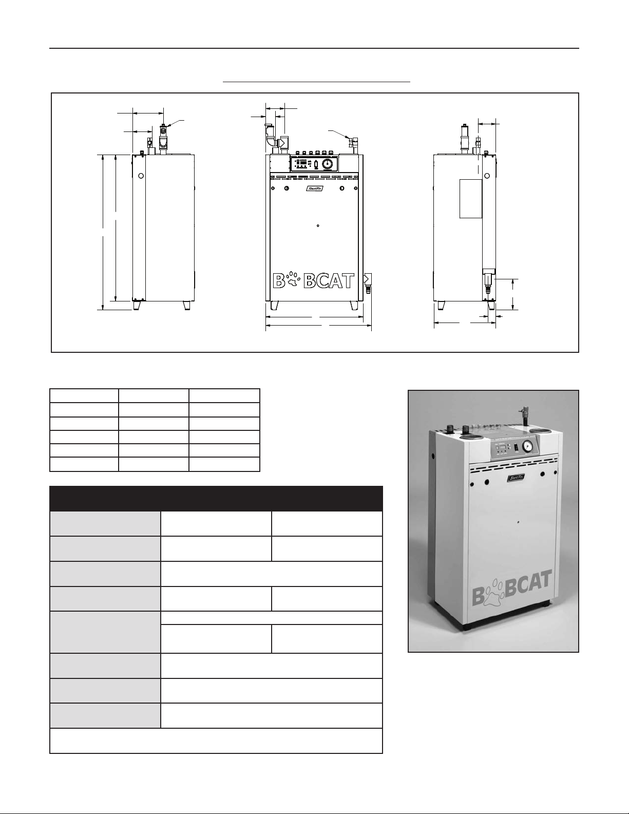
Bobcat Models B-120A and B-200A
RATINGS AND DIMENSIONS
Figure 1. Dimensions data
Dimension B-120A B-200A
A 22 30
B 23 7/8 31 7/8
C 33 38
D 35 40
E 7 10
SPECIFICATIONS:
Fuel Rate Input:
Boiler Water Volume:
Water Piping
Connections:
Weight of Boiler
(uncrated):
Gas orifice siz
Gas Piping Connection:
Vent Connection:
B-120A Boiler B-200A Boiler
120,000 BTUH max
30,000 BTUH min
1.0 gallon (8.3 lbs) 1.4 gallon (11.07 lbs)
145 lbs. 200 lbs.
1” NPT (male)
Natural Gas - No or
e:
Propane - .2025” inside
diameter
**
1/2” NPT (female)
pipe (PVC
nominal I.D
3”
.
200,000 BTUH max
50,000 BTUH min
ifice used*
Propane - .2600” inside
diameter
**
, CPVC or stainless steel)
Bobcat Boiler
Air Intake Connection:
No or
*Note:
**See page 42 f
3” nominal I.D. pipe (PVC, CPVC or stainless steel)
ifice changes are required f
or conversion procedure to propane.
or high altitude installations
.
Page 3
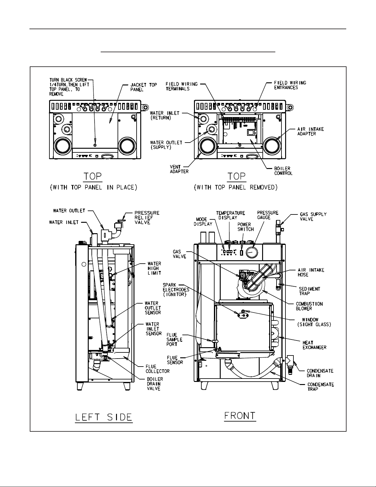
Bobcat Models B-120A and B-200A
LOCATION AND IDENTIFICATION OF PARTS
3
Figure 2.
Location and identification of parts (model B-120A is shown)
Page 4
4
: 2" FOR ENCLOSED
*
1"
3"
6"
*
2"
2"
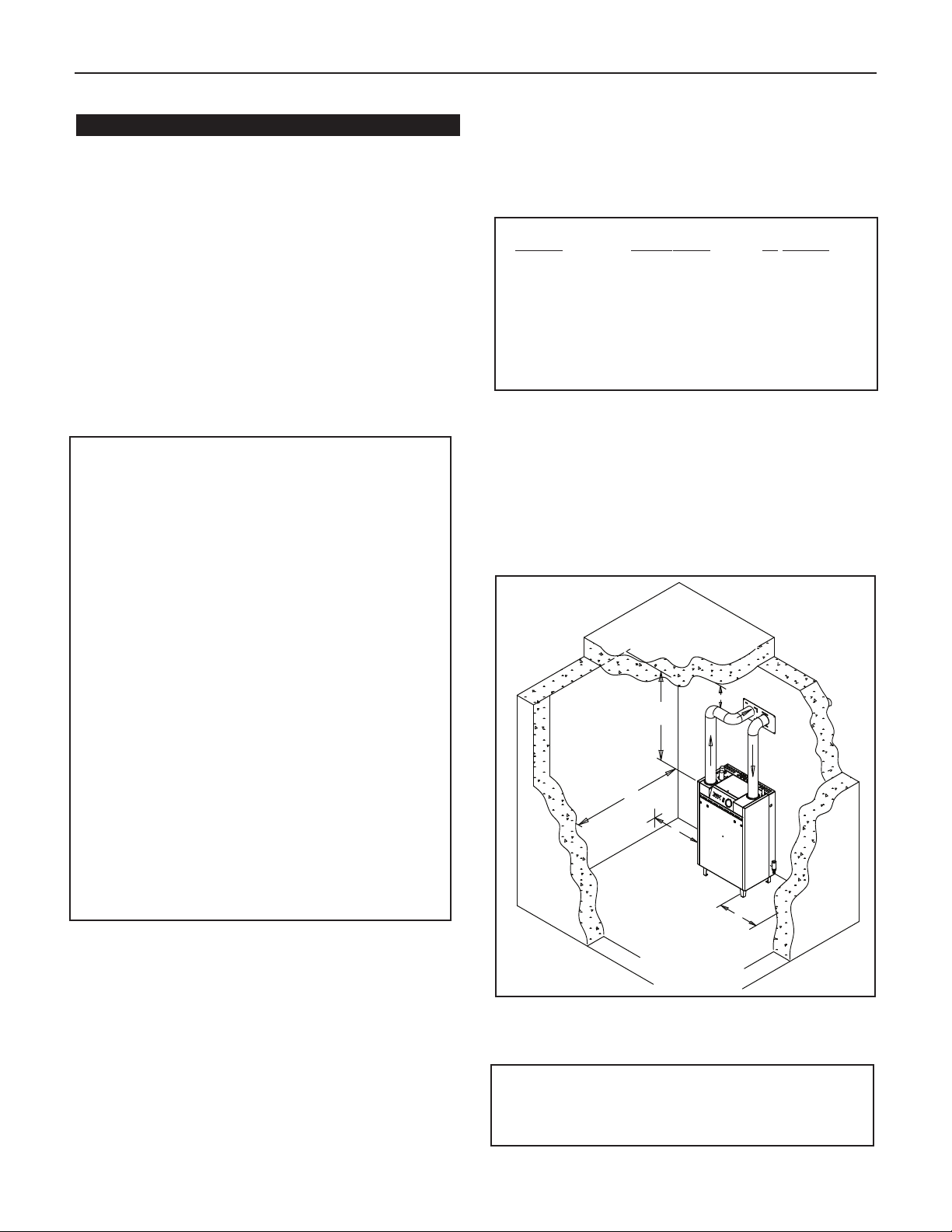
Bobcat Models B-120A and B-200A
INSTALLATION REQUIREMENTS
The installation must conform to the requirements of the
authority having jurisdiction or, in the absence of such
requirements, to the National Fuel Gas Code, ANSI Z223.1latest edition.
This installation must also conform to the additional require-
ents in this Slant/Fin Instruction Book.
m
BOILER LOCATION
Provide a level, solid foundation or vertical wall for the boiler.
Location should be as near as possible to chimney or outside
wall so that the flue pipe from boiler is short and direct. (See
paragraph heading “Vent Termination Location and Clearance” on page 9.) The location should also be such that all
boiler components are protected from water (dripping, spraying, rain, etc.) during appliance operation and service (circulator replacement, control replacement, etc.).
WARNING
LIQUEFIED PETROLEUM (L.P.) PROPANE GAS-FIRED
BOILER LOCATION
REQUIRES SPECIAL ATTENTION
Liquefied Petroleum (L.P.) propane gas is
Therefore, propane boilers, piping, valves should NOT be
installed in locations where propane leaking from defective
equipment and piping will "pool" in a basement or other
space below the leak.
A spark or flame from the boiler or other source may ignite
the accumulated propane gas causing an explosion or fire.
Provide a level, solid foundation for the boiler. Location
should be as near the chimney as possible so that the flue
pipe from boiler to chimney is short and direct.
The UNIFORM MECHANICAL CODE may be in effect in
your geographic area.
The following precautions are cited by the 1994 UNIFORM
MECHANICAL CODE, section 304.6:
"LPG Appliances. Liquefied petroleum gas-burning
appliances shall not be installed in a pit, basement or
similar location where heavier-than-air-gas might collect.
Appliances so fueled shall not be installed in an abo
grade under-floor space or basement unless such location is pro
unbur
Consult Chapter 5 of the 1994 UNIFORM MECHANICAL
CODE f
remov
BOILER FOUNDA
A. Provide a solid, level foundation or vertical wall capable of
suppor
xtending at least 2" past the jac
e
dimensions of boilers, page 2. See also figure 4a & 4b for
mounting the boiler on the wall.
Boiler can be installed on both comb
.
B
non-comb
above carpeting.
C. If boiler is to be located over buried conduit containing
electric wires or telephone cables, consult local codes or
the National Board of Fire Underwr
requirements.
vided with an approv
ned gas."
or design criter
al of unbur
ned gas
ting the w
le floors, but must NOT be installed on or
ustib
ia of the "approv
.
TION
eight of the boiler filled with w
ed means for remo
heavier than air.
val of
le and
or
ater
, and
ed" means f
ket on all sides. See
ustib
or specific
iters f
ve-
MINIMUM CLEARANCES FROM COMBUSTIBLE
CONSTRUCTIONS
. Minimum clearances to the exterior surfaces of the boiler
A
shall be as follows:
INIMUM ALCOVE AND CLOSET CLEARANCE
M
or Combustible Recommended
F
Surf
ace Construction for Service
ront 6" 18"
F
Rear 0" 0"
Left Side 2" 8"
Right Side 2" 8"
op 3" 18"
T
Flue Connector:
Enclosed — 2" 6"
Uninclosed — 1" 6"
B. Provide accessibility clearance of 8" on sides requiring
servicing and 18" on sides used for passage.
C. All minimum clearances shown above must be met. This
may result in increased values of some minimum clearances in order to maintain the minimum clearances of
others.
D. Clearance from hot water pipes shall be 1 inch**.
t points where hot water pipes emerge from a floor,
** A
the clearance at the opening through the finished floor boards or wall
or ceiling boards may be not less than 1/2 inch. Each such opening
shall be covered with a plate of uncombustible material.
Figure 3. Bobcat boiler min. clearances for combustible
construction.
SAFETY
THE BOILER AREA CLEAR AND FREE FR
KEEP
COMBUSTIBLE MATERIALS, GASOLINE AND OTHER
FLAMMABLE VAPORS AND LIQUIDS.
wall or ceiling,
OM
Page 5
Bobcat Models B-120A and B-200A
CONTAMINATION PREVENTION
The combustion air supply must not be susceptible to contamination sources, whether the combustion air comes from the
interior or exterior of the building. Contaminated air can cause
orrosion or other damage to the heat exchanger and compo-
c
nents of the boiler, causing failure of these parts or unsafe
operation.
Below is a list of products and areas which may cause
contaminated combustion air:
PRODUCTS TO AVOID
• Spray cans containing chloro/fluorocarbons
• Permanent wave solutions
• Chlorinated waxes/cleaners
• Chlorine-based swimming pool chemicals
• Calcium chloride used for thawing
• Sodium chloride used for water softening
• Refrigerant leaks
• Paint or varnish removers
• Hydrochloric acid/muriatic acid
• Cements and glues
• Antistatic fabric softeners used in clothes dryers
• Chlorine-type bleaches, detergents, and cleaning
solvents found in household laundry rooms
• Adhesives used to fasten building products and other
similar products
5
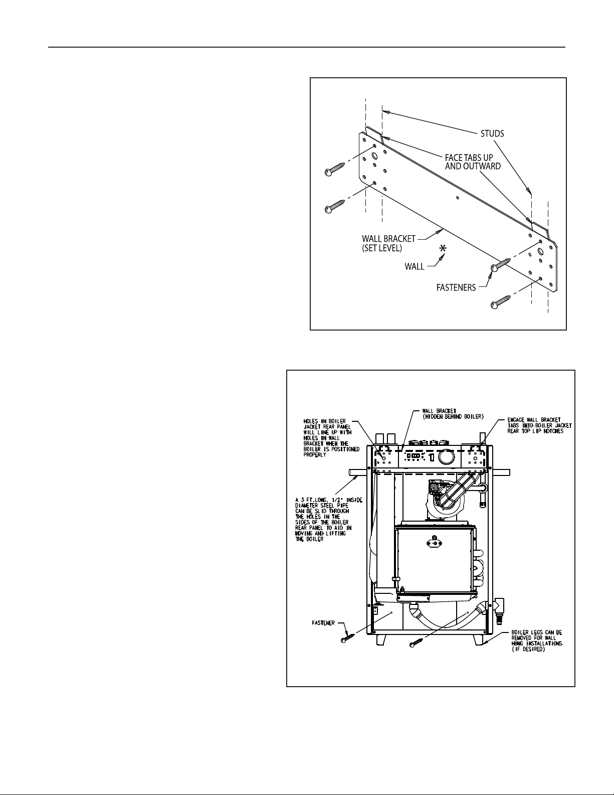
Figure 4a. Wall bracket securement
AREAS LIKELY TO HAVE CONTAMINANTS
• Dry cleaning/laundry areas and establishments
• Swimming pools
• Metal fabrication plants
• Beauty shops
• Refrigeration repair shops
• Photo processing plants
• Auto body shops
• Plastic manufacturing plants
• Furniture refinishing areas and establishments
• New building construction
• Remodeling areas
• Garages with workshops
Figure 4b. Mounting boiler on the wall
Page 6

6
MOUNTING THE BOILER ON A WALL
Be sure that the wall is vertically plumb and capable of carrying
the weight of the boiler and the system piping, when full of
water. See page 2 for the boiler weight.
e sure that there are studs available in the proper locations,
B
for securing the boiler wall bracket and back panel.
(See Figures 4a and 4b).
For wood stud walls, use lag screws or wood screws with a
coarse thread and a minimum of 3” in length.
For metal stud walls, use toggle-style bolts that are specifically
esigned for such and maximum capacity exceeds the weight
d
of the boiler and the system piping when full of water.
DO NOT use anchors driven into sheetrock to hold the boiler
up on the wall. If mounting the boiler on a cement wall, use
anchors that are specifically designed for such, and maximum
capacity exceeds the weight of the boiler and the system
piping, when full of water.
A. INSTALL THE WALL BRACKET. SEE FIGURE 4a.
1. Remove the wall bracket from the boiler jacket rear panel,
by unfastening the single screw that holds it in place, for
shipping purposes only.
2. Select the location on the wall where the boiler will be
mounted. The upward facing tabs of the wall bracket will
align with the top surface of the boiler jacket, and 3 feet of
open wall space will be needed to accommodate the boiler
jacket rear panel below this.
Bobcat Models B-120A and B-200A
. Lift the boiler up against the wall, with the top edge of the
4
acket slightly above the wall bracket tabs. There are 2
j
holes in the upper corners of the jacket rear panel, that
can visually be aligned with the 2 larger diameter holes in
the wall bracket, to ensure that the wall bracket tabs line
up and engage with the boiler jacket near top lip notches
properly.
. There are 2 fastener holes in the lower area of the boiler
5
ear panel, just below the flue collector, for insuring the
r
oiler does not move off the wall bracket. Mark these 2
b
holes, with the boiler in place, then lift the boiler off the wall
bracket.
6. Determine which fastener type will best engage with the
wall construction at the location of the 2 market holes. Drill
out the appropriate diameter and depth holes for the
fasteners, where marked.
7. Lift the boiler up onto the wall bracket again, as described
in Step 4. Secure the boiler to the wall, with the 2 fasteners
in the lower rear panel area.
8. If able to, the 1/2” diameter lifting pipe should be removed
from the boiler rear panel.
9. The 4 boiler legs may be removed at this time, if desired. 2
screws hold each leg in place, from inside the jacket
panel.
10. The boiler side panels can be replaced at this time, but the
front panel should be left off, for the startup procedure
later in the installation.
3. For sheetrock and stud construction, locate the studs and
determine which set of holes in the wall bracket best align
with the center of the studs. For cement walls, determine
a location for the wall bracket to mount where the anchors
will be secure, devoid of seams or cracks.
4. Place the bracket in the selected location, with the 2 tabs
positioned up and facing outward, level it out, and mark
the holes to be used. A minimum of 4 of these holes must
be utilized, regardless of w
5. Drill the appropriate diameter and depth holes for the
fasteners used in the wall, where marked.
6. Fasten the wall bracket to the wall, being sure that the
tabs face upward and outward, and the fasteners have
engaged the w
B. INSTALL THE BOILER ON THE WALL. SEE FIGURE 4b.
1. Remove the boiler jacket front cover, by turning the 2 black
screws 1/4 turn to the open position, then lifting off.
2. Remove both the boiler jacket side panels, by removing
the 2 sheetmetal screws in the top and bottom front edge,
then lift off.
3. To aid in lifting the boiler, a 3 foot long, 1/2” inside diameter
steel pipe can be slid through the holes in the sides of the
boiler rear panel. Let the pipe extend out each side of the
jacket evenly, for hand-holds, and pick up the boiler without
letting it tilt, for safety.
all proper
all material.
ly.
VENTING APPLICATION
The Bobcat B-120 and B-200 are sealed combustion type
boilers, they may be installed and vented either as a direct vent
boiler which all air for combustion is obtained directly from outside or as a non-direct vent boiler which air for combustion is
taken from inside the boiler room.
The Bobcat B-120 and B-200 boilers must be vented by 3"
diameter PVC/CPVC schedule 40 pipe, or the proper 3” diameter stainless steel venting system (see “vent material” on page
7) through the roof or sidewall.
BOILER ROOM AIR SUPPLY AND VENTILATION
An ample supply of air is required for combustion and ventilation. When buildings are insulated, caulked and weatherstripped, now or later on, direct openings to outside may be
required and should be provided. If the boiler is not near an
outside wall, air may be ducted to it from outside wall openings.
Provisions for combustion and ventilation air must be made in
accordance with section 5.3, Air for Combustion and Ventilation, of the National Fuel Gas Code, ANSI Z223.1-latest edi
tion, or applicable provisions of the local building codes. The
following recommendation applies to buildings of energy-saving
construction, fully caulked and weatherstripped.
INSTALLATION IN ENCLOSED BOILER ROOM REQUIRES
O UNOBSTRUCTED OPENINGS FOR PASSAGE OF AIR
TW
INTO THE BOILER ROOM:
-
Page 7

Bobcat Models B-120A and B-200A
7
A. NON-DIRECT VENT INSTALLATION
1. Air drawn horizontally from outdoors DIRECTLY through
n outside wall;
a
ne louvered opening near the floor and
o
one louvered opening near the ceiling, each opening with a
minimum FREE air passage area of
1 square inch per 4000
Btuh of total appliances’ input.
2.
Air drawn horizontally through HORIZONTAL DUCTS;
ne opening near the floor and one opening near the ceiling,
o
each opening with a minimum FREE air passage area of
1
square inch per 2000 Btuh of total appliances’ input.
Air drawn VERTICALLY from outdoors; one opening at the
3.
floor and one opening at the ceiling, each opening with a
inimum FREE air passage area of
m
square inchper 4000
1
Btuh of total appliances’ input.
4.
Air drawn from inside the building; one opening near the
floor and one opening near the ceiling, each opening with a
minimum FREE air passage area of
1 square inch per 1000
Btuh of total appliances’ input.
IF BOILERS ARE INSTALLED ADJACENT TO OTHER FUEL
BURNING EQUIPMENT, THE AREA OF FREE OPENINGS
MUST BE APPROPRIATELY INCREASED TO ACCOMMODATE
THE ADDITIONAL LOAD.
B. DIRECT VENT INSTALLATION
Adequate air supply should be provided to prevent overheating of
the boiler controls and boiler room. Openings for passage of air
into the boiler room for direct-vent installation must be at least
1
⁄2
of the openings required for the non-direct vent as
mentioned above.
If additional non-direct vent appliances are installed in the same
space and adequate air openings are provided for them, there
are no additional air openings required for the Bobcat
B-120 and B-200 boilers.
For both direct and non-direct installation, the following must be
considered:
- Openings must never be reduced or closed. If doors or
windows are used for air supply, they must be locked
open.
- Protect against closure of openings by snow and debris.
Inspect frequently.
No mechanical draft exhaust or supply fans are to be
-
used in or near the boiler area.
- Boiler area must never be under negative pressure.The
w of combustion and v
flo
entilating air to the boiler m
ust
not be obstructed.
FLUE GAS VENTING REQUIREMENTS
The Bobcat B-120 and B-200 series boilers are high efficiency,
mechanically f
enting arrangements than natural draft, lower efficiency boilers.
v
THE FOLLO
READ AND FOLLO
orced draft boilers and, theref
WING INSTR
UCTIONS MUST BE CAREFULL
WED IN ORDER T
ore, require different
VOID ANY HAZ-
O A
Y
ARDOUS CONDITIONS DUE TO IMPROPER INSTALLATION
OF THE AIR INTAKE AND FLUE GAS VENTING SYSTEM.
The vent piping installation MUST be in accordance with these
uctions and with ANSI Z223.1-latest edition NA
instr
TIONAL
FUEL GAS CODE, Part 7, Venting of Equipment. Other local
codes may also apply and must be followed. Where there is a
conflict betw
shall apply
boiler ser
.
ies.
een these requirements
The use of a v
ent damper is NOT permitted on this
, the more str
ingent case
ADDITIONAL REQUIREMENTS FOR THE COMMONWEALTH
OF MASSACHUSETTS
When the Bobcat is installed and used in the Commonwealth of Massachusetts, the following additional requirements pursuant to Massachusetts
code 248 CMR MUST be met:
(1). Exisiting chimneys shall be permitted to have their use continued
when a gas conversion burner is installed, and shall be equipped with a
manual reset device that will automatically shut off gas to the burner in the
event of a sustained back-draft.
(2)(a). For all side wall horizontally vented gas fueld equipment installed in
every dwelling, building or structure used in whole or part for residential
purposes, including those owned or operated by the Commonwealth and
where the side wall exhaust vent termination is less than seven (7) feet
above finsihed grade in the area of the venting, including but not limited to
decks and porches, the following requirements shall be satisfied:
1. INSTALLATION OF CARBON MONOXIDE DETECTORS. At the time
of installation of the side wall horizontal vented fueled equipment, the
installing plumber or gasfitter shall observe that a hard wired carbon
monoxide detector with an alarm and battery back-up is installed on the
floor level where the gas equipment is to be installed. In addition, the
installing plumber or gasfitter shall observe that a battery operated or hard
wired carbon monoxide detector with an alarm is installed on each additional level of the dwelling, building or structure served by the side wall
horizontal vented gas fueled equipment. It shall be the responsibility of the
property owner to secure the services of qualified licensed professionals
for the installation of hard wired carbon monoxide detectors.
a. In the event that the side wall horizontally vented gas fueld equipment
is installed in a crawl space or an attic, the hard wired carbon monoxide
k up may be installed on the next adja-
detector with alarm and batter
cent floor le
b. In th event that the requirements of this subdivision can not be met at
the time of completion of installation, the o
ty (30) days to comply with the above requirements; provided, however,
that dur
detector with an alarm shall be installed.
2. APPROVED CARBON MONOXIDE DETECTORS. Each carbon
monoxide detector as required in accordance with the above provisions
shall comply with NFPA 720 and be ANSI/UL 2034 listed and IAS certified.
3.
mounted to the exterior of the building at a minimum height of eight (8)
feet above grade directly in line with the exhaust vent terminal for the hori-
ontally v
z
read, in print size no less that one-half (1/2) inch in size,
DIRECTLY BELOW, KEEP CLEAR OF ALL OBSTRUCTIONS”.
4. INSPECTION. The state or local gas inspector of the side wall horizontally vented gas fueled equipment shall not approve the installation unless,
upon inspection, the inspector obser
signage installed in accordance with the provisions of 248 CMR
5.08(2)(a)1 through 4.
(b) EXEMPTIONS. The following equipment is exempt from 248 CMR
5.08(2)(a)1 through 4:
1.
Required TO Be Vented” in the most current edition of NFPA 54 as
adopted by the Board; and
2. Product Approved side wall horizontally vented gas fueled equipment installed in a room or str
ing or structure used in whole or part for residential purposes.
vel.
ing said thir
SIGNA
ented gas fueled heating appliance or equipment. The sign shall
The equipment listed in Chapter 10 entitled
ty (30) day period, a battery operated carbon monoxide
A metal or plastic identification plate shall be per
GE.
y bac
es carbon mono
v
ucture separ
wner shall have a period of thir-
manently
“GAS VENT
xide detectors and
“Equipment Not
ate from the dw
elling, build-
Page 8
8
Bobcat Models B-120A and B-200A
ENT AND AIR INTAKE MATERIALS
V
The vent and air intake system for direct or non-direct vent
installation must be 3” diameter PVC/CPVC schedule. 40 pipe,
or UL listed single wall 3” diameter AL29-4C* stainless steel
aterial. The following manufacturers’ systems are approved
m
for use within a specified minimum and maximum equivalent
vent length in this manual.
Manufacturer
Heat-Fab. Inc. Saf-T Vent Not Required
ProTech System, FasNSeal Not Required
Inc.
Flex-L StaR-34 GE-IS806
International, Inc.
Z-Flex, Inc. Z-Vent GE, RTV 106
N/A PVC pipe, PVC primer
N/A CPVC pipe, CPVC primer
*AL29-4C is a registered Trademark of Allegheny Ludlum Corp
Type/System
EZ Seal
Schedule 40 and cement
Schedule 40 and cement
Sealant
When joining the various components of the listed stainless
steel vent systems, the manufacturers’ instructions should be
closely followed to insure proper sealing. Use sealant specified
by vent system manufacturer for sealing of pipe and fittings, if
required. When joining the PVC/CPVC pipe and fittings, follow
the instructions provided in this manual. All connections must
be liquid and pressure tight. DO NOT use galvanized flue pipe
or any plastic-type materials other than PVC/CPVC Schedule
40.
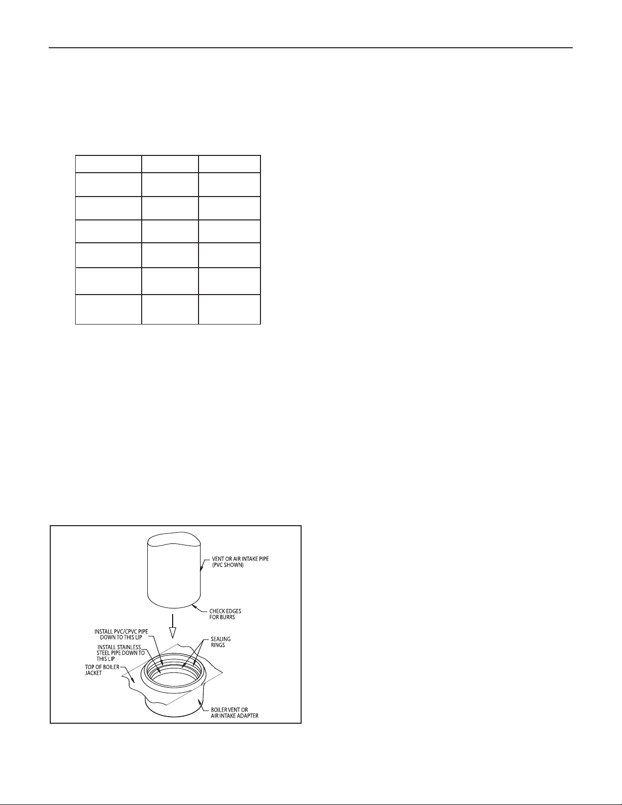
The integral adapters on the boiler are designed to accommodate either PVC/CPVC Schedule 40 pipe or the listed stainless
steel vent systems.These adapters have built-in sealing rings,
so no additional sealant is required. Make sure the pipes are
round and burr-free, and push down into the appropriate step
of the adapter, until sn
ug. (See Figure 5).
PVC/CPVC PIPE GENERAL ASSEMBLY METHOD
The following are the recommended methods for cutting,
cleaning and connecting PVC and CPVC pipe, for both the
vent and air intake piping system:
1. When laying out the piping system, work from the boiler
vent and air intake adapter to the point of outside
ermination.
t
2. Cut the PVC/CPVC pipe to the required lengths, and
pre-assemble the entire system, before sealing.
Disassembly after sealing, to make any corrections, will not
e possible.
b
3. Once the pre-assembled PVC/CPVC pipe vent and air
intake system is verified to be of the proper length pipe and
fitting orientation, begin disassembling and preparing the
pipes and fittings for the sealing process.This can be done
section by section, or the complete vent and air intake
system can be disassembled. It is recommended to mark
the various parts, before complete disassembly, to
eliminate the possibility of errors during re-assembly.
4. De-burr the inside and outside of every PVC/CPVC pipe, to
ensure that they engage fully into the fittings, and flow is
not compromised. A small chamfer on the outside of each
pipe can particularly aid in the final assembly process.
5. Wipe or knock out any debris from inside the PVC or
CPVC pipe, which may have accumulated there from the
cutting process or storage. Debris can cause operational
problems with the boiler combustion components.
6. Thoroughly clean the outside ends of each pipe, and the
inside of each fitting. The surfaces must be dry for the
sealing agents to work properly. Handle the prepared pipe
lengths away from the cleaned ends, and handle the
cleaned fittings, from the outside, to avoid contamination.
7. Re-assembly of the PVC or CPVC pipe should be done in
sections, to avoid the primer and cement drying before the
parts are engaged.
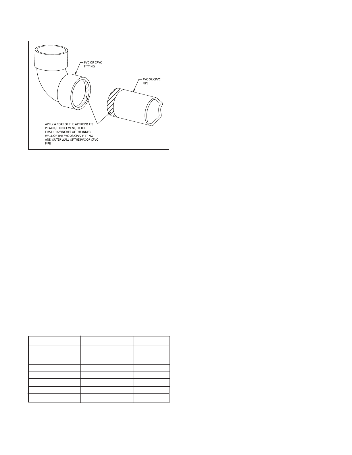
8. For each joint, first apply a coat of primer to the outside
sealing surface of the pipe and the inside sealing surface of
each fitting. Use only the primer type that is specified for
either the PVC or CPVC pipe that is bing utilized.
9. Before the primer dries, apply a coat of cement over it. A
second coat of cement can be applied, if necessary, but
must be done quickly and in a manner that avoids
unnecessar
uild-up that w
y b
ould cause obstr
the system. Use only the cement type that is specified f
either the PVC or CPVC pipe that is being utiliz
uction inside
or
ed.
10. Before the cement dries, insert the pipe into the fitting. A
slight twisting motion while pushing the pipe into the fitting
will aid in distrib
par
ts fully engage.
uting the cement evenly and ensuring the
11. Quickly wipe the excess cement from the outside areas of
the joint.
Discard an
ags used to a
y r
void later getting the
cement on hands, clothes and equipment.
Figure 5.
Adapter
Vent and Air Intake Pipe installation into Boiler
.
VENT AND AIR INTAKE RESTRICTIONS
1. Maximum allowed equivalent vent and air intake length for
all of the approved vent and air intake materials is 100 feet
for B-120 and 50 feet for B-200.
2. Equivalent of vent or air intake length is sum of the
straight pipe lengths and equivalent length of elbows as
wn in the tab
sho
le on this page.
Page 9
Bobcat Models B-120A and B-200A
Figure 6.
3. The vent termination is in addition to the allowed
equivalent lengths.
4. Minimum vent length is 2 feet of straight pipe, plus the one
90˚ elbow that is required.
5. Vent length restriction is for both direct and non-direct
vent installations.
9
. The B-120 and B-200 boilers are equipped with a built-in
6
ondensation drain and trap.The trap must be filled with
c
water. DO NOT operate the boiler without filling the trap with
water to prevent flue gas discharge into space. The drain
must dispose of possibly large quantities of condensate,
which may require a neutralizing system. Refer to the
“Condensate Drainage” section of this manual. No additional
condensation drain and trap is required on the vent piping
system itself.
. The horizontal vent pipe must be sloped upward from the
7
boiler at a pitch of at least 1/4” per 1 foot of run, so that
the condensate from the vent system runs to the boiler
vent adapter pipe, then out the built-in condensation drain
and trap.
8. The horizontal vent and air intake pipes must be supported
with pipe straps, at intervals no greater than 5 feet, when
PVC/CPVC pipe is utilized. This support spacing applies
also to stainless steel vent pipe, unless the manufacturer’s
instructions permit otherwise. The vertical vent and air
intake pipes also must be supported, wherever the building
construction provides allowance for it, such as ceiling or
roof passage openings where a firestop and support or
braces can be affixed.
9. Minimum clearances of vent pipes from combustible
constructions must be maintained (see Page 4). No
clearance is required between the vent and air intake pipes
of this boiler.
EXAMPLE: Boiler model B-120 is to be installed. The
combustion air is provided by air intake piping directly to the
boiler (direct-vent installation). The vent piping will be PVC
and installation location will require the use of 4 elbows for
the vent to run the termination. The air intake piping will also
be PVC, and also will require the use of 4 elbows.
In this case, the maximum straight pipe vent length that can
be utilized with the 4 elbows would be: 100’ - (4’ x 5’) = 80’.
Since the air intake pipe also is PVC and requires the use of
4 elbows, the maximum straight pipe air intake length that
can be utilized is also 80 feet.
If the air for combustion were taken from the boiler room
(non-direct vent installation), still the maximum straight vent
length would be 80 feet.
Equivalent Length of Various 90-Degree Elbows
Manufacturer
, Inc. Saf-T Standard 3
ab
Heat-F
Heat-Fab, Inc. Saf-T, tight radius elbow 6
ech System, Inc.
ProT
Flex-L International, Inc. StaR-34 6
Z-Flex, Inc. Z-Vent 6
N/A PVC, Schedule 40 5
N/A
ype/System
T
elbow
asNseal
F
, Schedule 40
CPVC
Equivalent
Length (Feet)
6
5
10. Common venting with other appliances or another Bobcat
boiler is not allowed.
11. DO NOT install a vent damper or similar devices in vent
system or on the boiler.
12. DO NOT insulate venting system.
Page 10

10
Bobcat Models B-120A and B-200A
VENTING INSTALLATION
Only PVC/CPVC and approved stainless steel materials listed
on page 8 may be used for the venting system installation. If
stainless steel vent systems are used, follow the manufactur-
r’s instructions, in conjunction with these instructions.
e
I. Non-Direct Vent Installation
The air for combustion is taken from the ambient air
surrounding the boiler; therefore, ample supply of air is required
for combustion and ventilation (see page 7.)
DO NOT use this installation method if the surrounding of the
boiler is contaminated. See page 5 for the list of harmful
contaminants and their sources, to avoid.
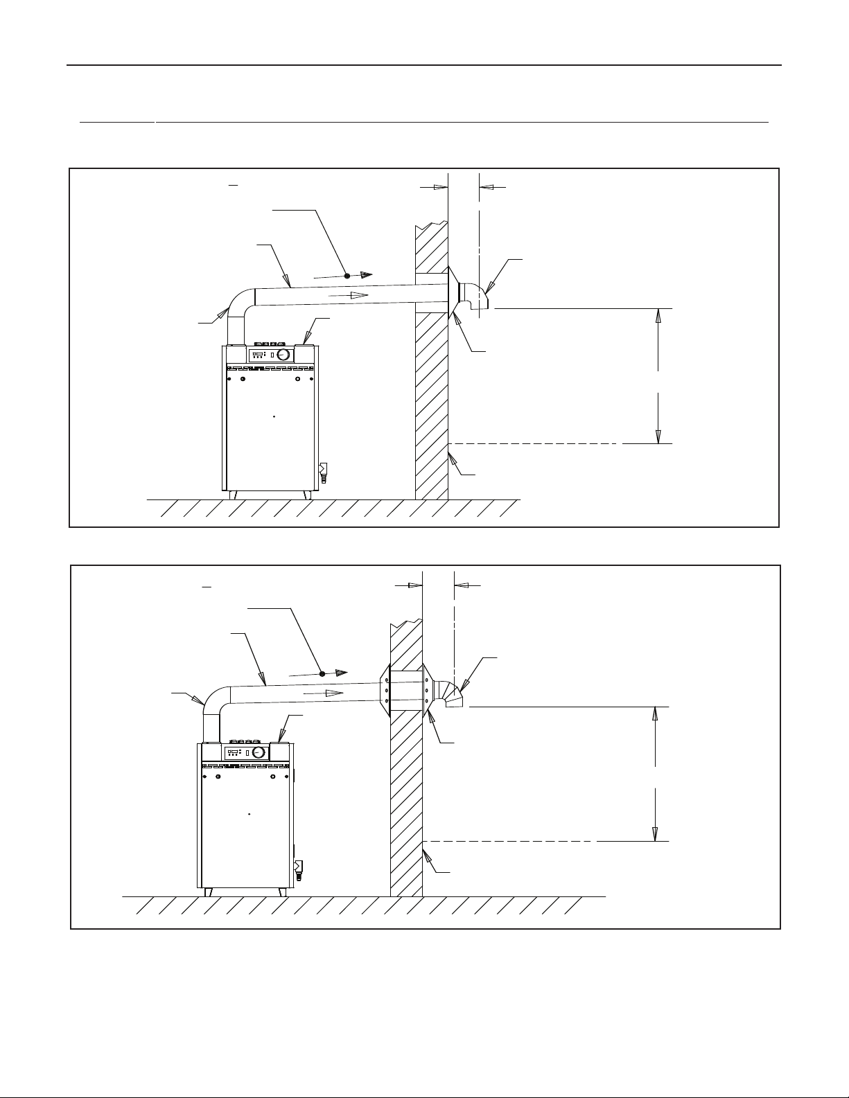
A. SIDEWALL VENTING - NON-DIRECT VENT
Figures 7 and 8 show typical horizontal sidewall venting. For
combustible wall passage of vent piping, a UL listed thimble
or flashing and sealing boot must be used, providing the wall
thickness from 3" minimum up to 12" maximum. The vent
piping must terminate with a screened tee or elbow termination
facing down.
CAUTION: Flue gasses exiting from the vent terminal will
condense. Building materials in the area of the vent terminal
should be protected from discoloration and degradation.
VENT TERMINATION LOCATION AND CLEARANCES
1. The venting system shall terminate at least 3 feet above
any forced air inlet located within 10 feet.
2. The venting system shall terminate at least 12 inches
below or 12 inches horizontally from any door, window
or gravity air inlet into any building.The bottom of the vent
terminal or air intake terminal shall be at least 12 inches
above grade or the normal snow level whichever is
greater.
3. Through the wall vents shall not terminate over public
walkways or over areas where condensate or vapor could
create a nuisance or hazard or could be detrimental to
the operation of regulators, relief valves or other equipment. Minimum clearance of 4 feet horizontal distance is
maintained, from electric meters, gas meters, regulators
and relief equipment.
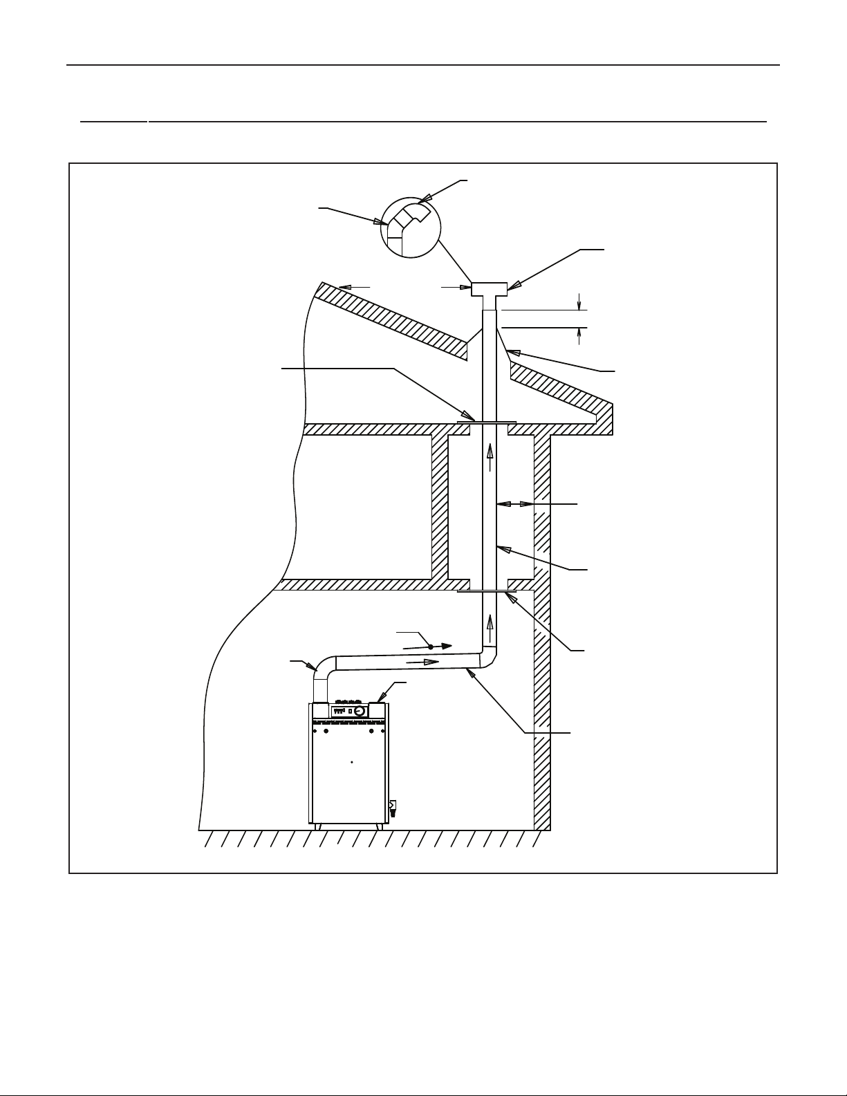
B. NON-DIRECT VENT - VERTICAL VENTING
Figure 9 shows typical venting through the roof.The vent pipe
must pass through the ceiling, floor and the roof vertically
hrough a 6" minimum diameter cutout. A fire stop is required
t
or each ceiling and floor penetration. For roof passage, an
f
appropriate UL listed roof flashing must be used.
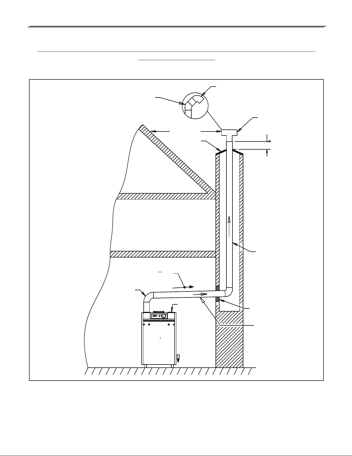
An existing chimney (see Figure 10) may be used as a chase
for vertical venting. Other appliances CANNOT be vented into
the same chimney or vent pipe within the chimney.
The vertical vent piping must terminate with a screened tee,
ombination of 45˚ elbow and a 90˚ screened elbow termina-
c
tion or a rain cap termination.
II. Direct Vent Installation
Air intake piping from outside to the boiler air intake adapter
provides the air for combustion.The boiler surrounding may be
contaminated (See page 5). Piping the air intake to the outside
can prevent contaminants from the boiler surrounding from
entering the combustion air supply.
A. SIDEWALL DIRECT VENTING
Figures 11 and 12 show typical sidewall direct venting, using a
Slant/Fin vent/air intake termination. There are 2 different models of vent/air intake termination available. One is designed
specifically for PVC/CPVC venting, and the other is designed
specifically for stainless steel venting systems. Only these 2
models of vent/air intake termination are approved for this
method of installation. Refer to the Slant/Fin Bobcat B-120 and
B-200 boilers Parts List (publication number B-10PL) for the
appropriate model for the vent material to be used.
CAUTION: Flue gasses existing from the vent terminal will condense. Building materials in the area of the terminal should be
protected from discoloration and degradation, in addition to the
requirements of the vent termination location and clearances
stated in this manual.
4. Vent termination must not be located in any confined
space (i.e.
any overhang or deck.Vent termination should not allow
flue gas discharge towards neighbor’s windows or where
personal injury or property damages can occur.
window w
ells
es, narrow alleys) or under
v
, alco
Page 11
Bobcat Models B-120A and B-200A
9 IN. MAX.
6
IN. MIN.
A
IR INTAKE
(DO NOT BL0CK)
O
UTSIDE WALL
SLOPE UP 1/4 IN.
PER FOOT MIN.
F
ROM BOILER TO
V
ENT TERMINATION
12" MIN
SNOW LINE
(
SEE DEFINITION)
T
ERMINATION 90˚ ELBOW
WITH SCREEN
90˚ ELBOW
S/FP/N 440695 (ADJUSTABLE
3 IN. DIA.
PVC/CVPC
P
IPE FOR
V
ENT
A U/L LISTED FLASHING
AND SEALING BOOT MUST
B
E USED ON COMBUSTIBLE
WALLS.
9 IN. MAX.
6 IN. MIN.
AIR INTAKE
(DO NOT BL0CK)
OUTSIDE WALL
SLOPE UP 1/4 IN.
PER FOOT MIN.
FROM BOILER TO
VENT TERMINATI ON
12" MIN
SNOW LINE
(SEE DEFINITION)
OUTSIDE VENT TERMINATION
90˚ ELBOW WITH SCREEN
STAN DARD
90˚ ELBOW
S/FP/N 440695 (ADJUSTABLE
3 INCH. DIA.
STAINLESS
STEEL VENTING
MATE RIAL FOR
VENT
A U/L LISTED WALL THIMBLE
MUST BE USED ON COMBUSTIBLE
WALLS. S/F P/N 440695
(ADJUSTABLE 5 IN.TO 8 IN.)
MAY BE USED. ABOVE THIMBLE
MUST BE USED WITH HEAT-FAB
SLIP JOINT CONNECTOR
BOBCAT MODELS B-120 and B-200 NON-DIRECT VENT, SIDEWALL VENTING
All joints must be liquid and pressure tight. Use 3” dia. PVC/CPVC schedule 40 pipe or U/L listed single wall 3" dia.
AL29-4C S.S.*. venting materials (See page 7).
11
Figure 7. Non-direct vent, side wall venting - utilizing PVC/CPVC pipe for venting.
Figure 8.
** Definition of Sno
Non-direct vent, side wall venting - utilizing stainless steel vent materials for venting.
wledge of local conditions will re
Kno
w Line:
The height should be used as the SNOW LINE.
AL 29-4C IS A REGISTERED
*
TRADEMARK OF ALLEGHENY LUDLUM CORP
eal the maxim
v
.
um height that repeated sno
alls accumulate to.
wf
Page 12
12
1 FT MIN.
SLOPE UP 1/4 IN.
PER FOOT MIN.
2" MIN
3 IN. DIA. PVC/CPVC
PIPE OR STAINLESS STEEL
VENTING MATERIAL FOR VENT
1
0 FT. MIN
RAIN CAP TERMINATION MAY BE USED
AIR INTAKE
(DO NOT BLOCK)
3 IN. DIA. PVC/CPVC
PIPE OR STAINLESS STEEL
VENTING MATERIAL FOR VENT
90˚ ELBOW
FIRESTOP AND
SUPPORT
F
LASHING AND
STORM COLLAR
VENT TERMINATI ON
TEE WITH SCREEN
90˚ TERMINATION
ELBOW WITH SCREEN
FIRESTOP AND
SUPPORT
ALTERNATE VERTICAL TERMINATION
45˚ ELBOW
*
*
Bobcat Models B-120A and B-200A
BOBCAT MODELS B-120 and B-200 NON-DIRECT VENT, VENTING THROUGH A ROOF
All joints must be liquid and pressure tight. Use 3” dia. PVC/CPVC schedule 40 pipe or U/L listed single wall 3" dia.
AL29-4C S.S.*. venting materials (See page 7).
Figure 9. Bobcat models B-120 and B-200 - non-direct vent, venting through the roof
AL 29-4C IS A REGISTERED TRADEMARK OF ALLEGHENY LUDLUM CORP
*
.
Page 13
Bobcat Models B-120A and B-200A
SEAL CHIMNEY OPENING
WITH MORTAR OR COVER PLATE
1 FT MIN.
SLOPE UP 1/4 IN.
PER FOOT MIN.
AIR INTAKE
(DO NOT BLO CK)
3 INCH DIA. PVC/CPVC
PIPE OR STAINLESS STEEL
VENTING MATERIAL FOR
VENT
10FT.MIN.
CHIMNEY
TOP PLATE
RAIN CAP TERMINATION MAY BE USED
VENT TERMINATI ON
TEE WITH SCREEN
90˚ TERMINATION
ELBOW WITH SCREEN
ALTERNATE VERTICAL TERMINATION
45˚ ELBOW
3 INCH DIA. PVC/CPVC
PIPE OR STAINLESS STEEL
VENTING MATERIAL FOR
VENT
90˚ ELBOW
*
*
BOBCAT MODELS B-120 and B-200 NON - DIRECT VENT, UTILIZING AN EXISTING
CHIMNEY AS A CHASE
All joints must be liquid and pressure tight. Use 3” dia. PVC/CPVC schedule 40 pipe or U/L listed single wall 3" dia.
AL29-4C S.S.*. venting materials (See page 7).
13
Figure 10. Bobcat models B-120 and B-200 - non-direct vent, utilizing an existing chimney as a chase.
AL 29-4C IS A REGISTERED
*
TRADEMARK OF ALLEGHENY LUDLUM CORP
.
Page 14
14
SLOPE UP 1/4"
PER FOOT MIN.
FROM BOILER TO
VENT TERMINATION
90˚ ELBOW
3" DIA.
PVC/CPVC
PIPE FOR
AIR INTAKE
SNOW
LIN
E**
(SEE
DEF
INIT
ION
)
AIR
INT
AKE
LOU
VER
S
12"MIN
O
UTSIDE
W
ALL
3
"
D
IA. PVC/CPVC
C
OUPLING WITH SCREEN
SLANT/FIN
VENT/AIR INTAKE
TERMINATION UNIT
PART # 860802
3"
– 16
"
THICK
WALL
3"
DIA.
PVC/CPVC
PIPE FOR
VENT
SLOPE UP 1/4”
PER FOOT MIN.
FROM BOILER TO
VENT TERMINATION
90˚ ELBOW
3" DIA.
STAINLESS
STEEL VENTING
MATERIAL FOR
VENT
3" DIA.
PVC/CPVC
PIPE FOR
AIR INTAK E
AIR
IN
TAK
E
LOU
VER
S
SNO
W L
INE
**
(SEE
DE
FIN
ITIO
N)
12"MIN
OUTSIDE
WALL
STRAIGHT SCREENED
VENT TERMINATI ON
SLANT/FIN
VENT/AIR INTAKE
TERMINATION UNIT
PART # 451138
3-12"
THICK
WALL
3
"
DIA.
HEAT-FAB SLIP
JOINT CONNECTOR
Bobcat Models B-120A and B-200A
BOBCAT MODELS B-120 and B-200 - DIRECT VENT, SIDEWALL VENTING
All joints must be liquid and pressure tight. Use 3” dia. PVC/CPVC schedule 40 pipe or U/L listed single wall 3" dia.
AL29-4C S.S.*. venting materials (See page 7).
Figure 11. Direct vent, sidewall venting illustration; utilizing PVC/CPVC pipe for venting
wall venting illustration;
w Line:
side
wledge of local conditions will reveal the maximum height that repeated snowfalls accumulate to.
Kno
Figure 12.
Direct vent,
** Definition of Sno
The height should be used as the SNOW LINE.
AL 29-4C IS A REGISTERED
*
TRADEMARK OF ALLEGHENY LUDLUM CORP
utilizing stainless steel vent materials f
.
or venting.
Page 15

Bobcat Models B-120A and B-200A
WALL
(
3"-18" THICK)
S
CREW
3" DIA.
P
VC/CPVC
PIPE FOR
A
IR INTAKE
S
TOP
FOR AIR/VENT
OUTSIDE TERMINAL
3" DIA.
PVC/CPVC
P
IPE FOR
VENT
F
LUE
GASES
W
ALL
(3"-12" THICK)
OUTSIDE
TERMINATION
PLATE
COMBUSTION
AIR
SEAL
H
ERE
O
UTSIDE
T
ERMINATION
PLATE
I
NSIDE
T
ERMINATION
P
LATE
I
NSIDE
T
ERMINATION
PLATE
3
" DIA.
PVC/CPVC
COUPLING
W
ITH SCREEN
L
OUVERS
3" DIA.
P
VC/CPVC
PIPE FOR
A
IR INTAKE
3" DIA.
PVC/CPVC
P
IPE FOR VENT
SCREW
3
" DIA.
PVC/CPVC
C
OUPLING
WITH SCREEN
WALL
(3"-12" THICK)
SCREW
3" DIA.
PVC/CPVC
PIPE FOR
AIR INTAKE
STOP
FOR AIR/VENT
OUTSIDE TERMINAL
4" GALV. PIPE
(WALL THIMBLE
FOR COMBUSTIBLE
WALLS ONLY)
3" DIA. AL29-4C
S.S.VENT PIPE
(SLIP JOINT CONNECTOR)
FLUE
GASES
WALL
(3"-12" THICK)
OUTSIDE
TERMINATION
PLATE
COMBUSTION
AIR
SEAL
HERE
DO NOT
SEAL HERE
OUTSIDE
TERMINATION
PLATE
INSIDE
T
ERMINATION
PLATE
INSIDE
TERMINATION
PLATE
STRAIGHT
SCREENED
TERMINATION
STRAIGHT
SCREENED
TERMINATION
LOUVERS
4" GALV. PIPE
(WALL THIMBLE)
3" DIA.
PVC/CPVC
P
IPE FOR
AIR INTAKE
3" DIA. AL29-4C
S.S.VENT PIPE
(SLIP JOINT
CONNECTOR)
SCREW
15
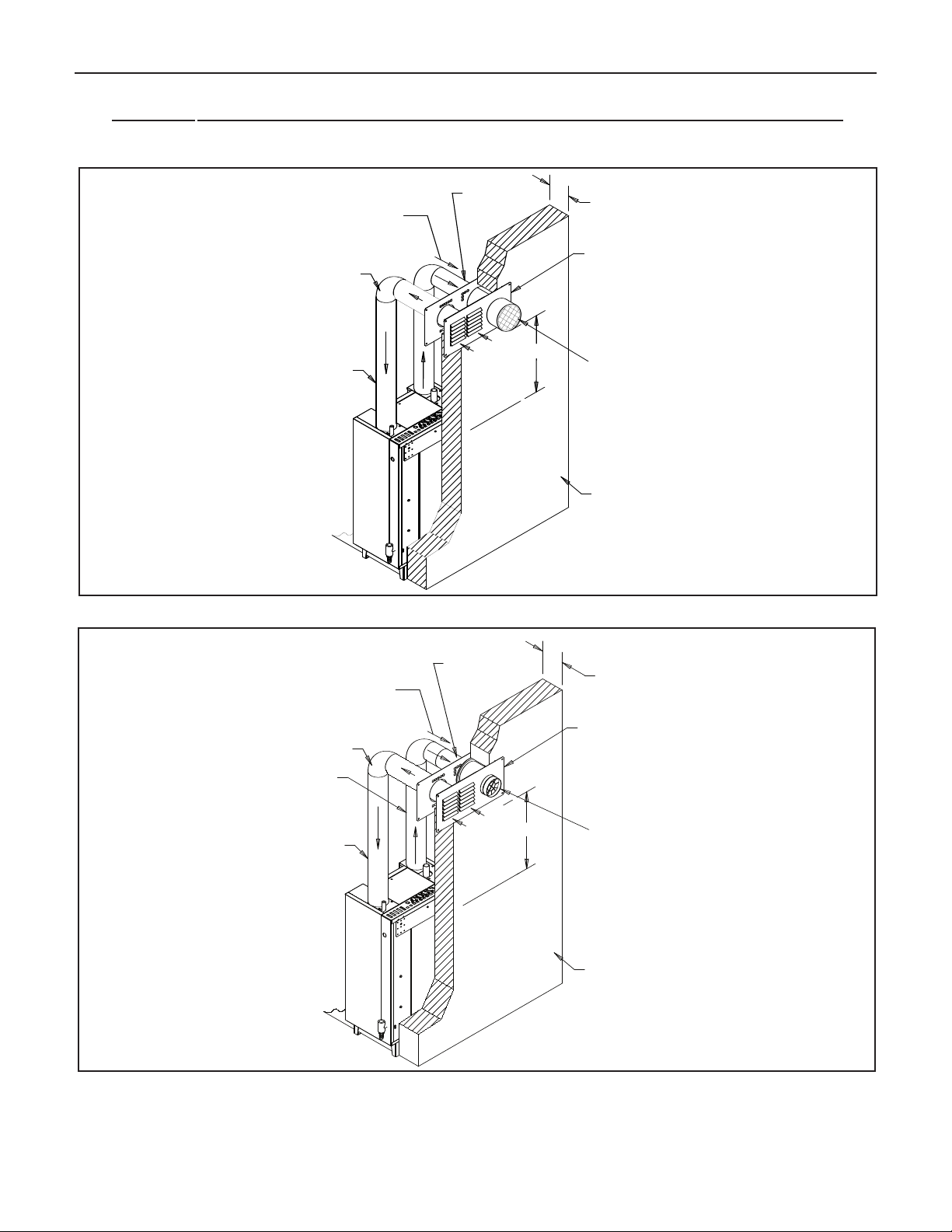
Figure 13a. Vent/Air intake termination; utilizing PVC/CPVC pipe for venting.
Figure 13b. Vent/Air intake termination; utilizing stainless steel venting materials.
Page 16

16
Bobcat Models B-120A and B-200A
ENT/AIR INTAKE TERMINATION FOR PVC/CPVC
V
ENTING INSTALLATION
V
This termination is designed specifically for 3” diameter PVC or
CPVC Schedule 40 pipe to be used as the vent and air intake
piping material, only. It can be used on a combustible wall,
provided the 1” minimum clearance of the vent pipe to any
combustible surface is maintained.
. Termination must be installed horizontally.
1
. Refer to Figure 13a for installation details.
2
3. Wall thickness should be 3” to 12” thick.
4. Follow instruction for “vent termination location and
clearances” explained on page 9.
5. Cut a rectangular opening with the following dimensions in
the wall.
Height: 5
Width: 12
1
⁄4”
3
⁄4”
6. From outside of the wall, install outside termination plate
using 4 screws. Make sure the louvers are at left side. Seal
the plate perimeter with silicon.
7. Apply a bead of silicon around the outer surface of the out
side termination plate air intake collar, about 1/2” from the
edge. This will seal the air intake pipe to the air intake
collar, in step #9.
8. From inside, install the inside termination plate, using 4
screws. Make sure that the holes for the vent and air intake
pipe visually line up with the vent passage hole and air
intake collar on the outside termination plate.
9. Cut the PVC or CPVC air intake pipe to the proper
dimension to fit onto the air intake collar of the terminal.
Slide the air intake pipe through the inside termination
plate and onto the air intake collar, where the sealant was
pre-applied in Step #7.
Cut the PVC or CPVC vent pipe so that it will extend out
10.
past the outer surface of the outside termination plate by
2”.
11. Cement a 3” diameter PVC or CPVC coupling onto the
PVC or CPVC vent pipe, and install a stainless steel
screen into the coupling.
ENT/AIR INTAKE TERMINATION FOR STAINLESS STEEL
V
ENTING INSTALLATION
V
This termination is designed specifically for Heat-Fab Saf-T
vent 3” diameter stainless steel venting system to be used as
the vent, and 3” diameter PVC or CPVC schedule 40 pipe to
be used as the air intake piping material, only. It can be used
on a combustible wall, provided a length of 4” diameter galvanized pipe is installed as a thimble around the vent pipe, for the
all passage.
w
. Termination must be installed horizontally.
1
2. Refer to Figure 13b for installation details.
3. Wall thickness should be 3” to 12” thick.
4. Follow instruction for “vent termination location and
clearances” explained on this page.
5. Cut a rectangular opening with the following dimensions in
the wall.
Height: 5
Width: 12
1
⁄4”
3
⁄4”
6. From outside of the wall, install outside termination plate
using 4 scre
ws. Make sure the louvers are at left side. Seal
the plate perimeter with silicon.
7. Apply a bead of silicon around the outer surface of the
outside termination plate air intake collar, about 1/2” from
the edge. This will seal the air intake pipe to the air intake
collar, in step #11.
8. For combustible wall a 4” galvanized pipe must be used as
a wall thimble.The length of the 4” galvanized pipe should
be approximately 1” shorter than the wall thickness.
9. From inside the building, fit galvanized pipe over 4” collar of
the outside plate.
10. From inside, install inside termination plate using 4 screws.
Make sure the 4” collar on the plate, penetrated into the
anized pipe.
galv
Cut the PVC or CPVC air intak
11.
e pipe to the proper
dimension to fit onto the air intake collar of the terminal.
Slide the air intake pipe through the inside termination
plate and onto the air intake collar, where the sealant was
pre-applied in Step #7.
12. From outside the wall, insert the bare end of the PVC or
CPVC vent pipe through the outside and inside terminal
plates, until the coupling is flush with the outside wall plate.
13. From inside, proceed with the air intake and vent pipe
installation. Follow the proper PVC/CPVC assembly
actices specified on page 8, and v
pr
enting system
restrictions specified on page 8 of this manual.
12. Assemble and seal straight screened termination to the slip
joint connector.
rom outside of the building, insert vent pipe (slip joint
F
13.
connector and termination assembly) through the 3” holes
of the outside and inside termination plate.
14. From inside, proceed with air intake and vent pipe
installation. Follow vent manufacturer’s instructions and
restrictions specified on page 8 of this manual.
Page 17
Bobcat Models B-120A and B-200A
SNO
W L
INE
1 FT.MIN.
1 FT.MIN.
STRAIGHT TERMINATI ON
WITH SCREEN
10 FT. MIN
FIRESTOP AND
SUPPORT
2" MIN.
SLOPE UP 1/4 IN.
PER FOOT MIN.
3
"
DIA. PVC/CPVC
OR STAINLESS
STEEL VENTING
MATERIAL FOR
VENT
3
"
DIA. PVC/CPVC
OR STAINLESS
STEEL PIPE FOR
AIR INTAKE
FIRESTOP AND
SUPPORT
PIPE
SUPPORT
FLASHING AND
STORM COLLAR
AIR INTAKE
180˚ ELBOW
WITH SCREEN
or PVC/CPVC pipe, follow the proper assembly practices
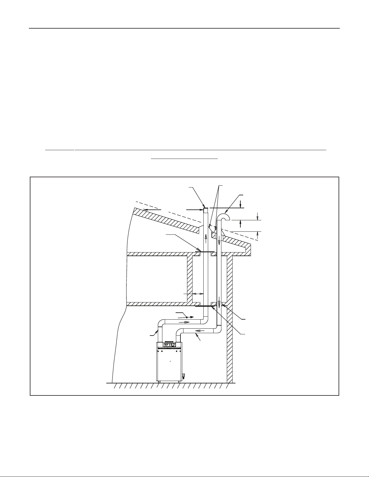
B. DIRECT VENT - VENTING AND AIR INTAKE
THROUGH A ROOF
F
pecified on page 8, and venting system restrictions specified
s
on page 8 of this manual. For stainless steel venting systems,
igure 14 shows typical vertical venting. The vent pipe must
F
ass through the ceiling, floor and the roof vertically through a
p
follow the vent manufacturer’s instructions and the restrictions
specified on page 8 of this manual
6” minimum diameter cutout. A fire stop is required for each
ceiling and floor penetration. For roof passage an appropriate
UL listed roof flashing must be used.
The vertical vent piping must terminate with a screened
straight termination. The air intake termination should be a
screened 180˚ elbow facing down.The air intake opening must
e at least 1 foot below the vent opening.
b
BOBCAT MODELS B-120 and B-200 - DIRECT VENT, VENTING AND AIR INTAKE
THROUGH A ROOF
All joints must be liquid and pressure tight. Use 3” dia. PVC/CPVC schedule 40 pipe or U/L listed single wall 3" dia.
AL29-4C S.S.*. venting materials (See page 7).
17
Figure 14. Direct vent, venting and air intake through a roof.
** Definition of Snow Line: Knowledge of local conditions will reveal the maximum height that repeated snowfalls accumulate to.
The height should be used as the SNOW LINE.
AL 29-4C IS A REGISTERED TRADEMARK OF ALLEGHENY LUDLUM CORP
*
.
Page 18

18
CONDENSATE TRAP,
FILLED WITH
WATER
DRAIN VACUUM
BREAKER, LEAVE
OPEN
PLASTIC
TUBING
NEUTRALIZING
UNIT
(IF REQUIRED)
CONDENSATE
PUMP
(IF REQUIRED)
DRAIN
INSIDE
BUILDING
VENTING AND AIR INTAKE SYSTEM REGULAR INSPECTION
A. Inspect the system regularly for condensation, corrosion,
agging and/or physical damage. A qualified professional
s
should service the boiler annually and include such an
inspection at that time. The homeowner should look over the
system monthly for damage, water stains, any signs of rust,
other corrosions or separation of the vent and air intake piping
(if direct-vent).
B. Should an inspection turn up signs of condensation, corrosion,
sagging or damage, the boiler should be shut down immediately and the condition should be corrected by a qualified
professional.
CONDENSATE REMOVAL SYSTEM
The Bobcat B-120 and B-200 boilers are equipped with a built-in
condensation drain and trap.The trap must be filled with water. DO
NOT operate the boiler without filling the trap with water to prevent
flue gas discharge into space. Periodic inspection should be made
of this assembly for deterioration of the tubing and to insure that
the trap is not plugged. If it is plugged or appears to have excessive sediment in it, it should be removed from the drain assembly,
straightened out to clear the obstruction, reformed, filled with water
and reinstalled as before.
A 3/4”
PVC tee, located on the right side of the boiler jacket, is
provided to run the condensate liquid from the boiler. Connect the
plastic tubing that will be run to the drain to the bottom take-off of
the tee. Leave the top take-off of the tee open, to act as a vacuum
breaker. If the building drain is above the bottom portion of the tee,
a condensate removal pump will be required.This pump must
have an overflow switch, and be compatible with the acidic condensate liquid, as must all fittings and the tubing used in this condensate removal system. (See Figure 15).
No part of the condensate removal system can be exposed to
freezing temperatures, or any other conditions that could cause
blockage. DO NOT run drain tubing to the outside of the building.
In addition, certain jurisdictions or drain pipe materials may require
a neutralization unit to be installed in the condensate removal system. Any piping other than plastic types will be subject to corrosion
ioration from the acidic condensate
or deter
vel as low as 3.0. A condensate filter containing lime, marble, or
le
phosphate chips can neutralize the condensate to a pH level
, which may have a pH
Bobcat Models B-120A and B-200A
bove 6.5, which is safe for all drain piping materials. (See Figure
a
5). The neutralizing filter medium will require periodic changing,
1
to ensure it’s affectiveness. Replacing the medium on an annual
basis is recommended, or refer to the manufacturer’s instructions
for systems that are available for neutralizing condensate.
COMMONWEALTH OF MASSACHUSETTS SPECIAL
REQUIREMENT
When the Bobcat B-120A and B-200A are installed and used in
the Commonwealth of Massachusetts, a neutralization unit MUST
be installed in the condensate removal system.
GAS PIPING
A. Local installation codes apply. The pipe joint compound used
on threads must be resistant to the action of liquefied petroleum gases.
B. The gas supply line to the boiler should run directly from the
meter for natural gas or from the fuel tank for L.P. propane gas.
A manual gas supply shut-off valve is provided on the boiler’s
gas supply pipe. (See Figure 2, on page 3). Local codes may
specify a manual main gas supply shut-off valve to be 5’ above
the floor, and a disconnection union at the gas piping entrance
to the boiler. In this case, unless the boiler is wall mounted at
the right height, the gas supply shut-off valve must be relocated
to the specified location. If the gas supply pipe must be upsized
for flow considerations, then the same size main gas supply
shut-off valve must be used.
Selecting pipe size for natural gas:
1. Measure or estimate the length of piping from the meter to
the installation site.
2. Consult gas supplier for heating value of gas (Btu/cu. ft.).
3. Divide boiler rated input by heating value to find gas flow in
piping (cu. ft. per hour).
4. Use table below to select proper pipe size.
EXAMPLE: Boiler model B-120 is to be installed. Distance from
gas meter to the boilers is 30ft. Heating value of natural gas is
1020 Btu/cu. Ft. Select proper pipe size.
Gas flow = 120,000 Btu/hour
1020 Btu/cu. ft.
= 118 cu. ft. per hour
Figure 15. Condensate disposal system
Page 19

Bobcat Models B-120A and B-200A
19
t 30 ft. length of pipe, match required capacity from table on
A
his page (choose higher capacity, in this case is 152 cu. ft. per
t
hour). Required pipe size is
mproper gas pipe sizing will result in flame outages, insuffi-
I
3
⁄4".
cient heat and other installation difficulties. For more information and also if other appliances are to be attached to the
piping system, see Appendix C of National Fuel Gas Code
ANSI Z223.1-latest edition.
C. The boiler and its gas connection must be leak tested
before replacing the boiler in operation. Use liquid soap
solution for all gas leak testing. DO NOT use open flame.
This boiler and it’s individual shutoff valve must be
disconnected from the gas supply piping system during and
pressure testing of that system at test pressures in excess
1
of
⁄2 PSIG. This boiler must be isolated from the gas supply
piping system by closing its individual manual shutoff valve
during any pressure testing of the gas supply piping system
at test pressures equal to or less than
1
⁄2 PSIG.
D. All gas piping used should be inspected thoroughly for
cleanliness before makeup. A sediment trap is integrally
provided, as illustrated on page 3.
E. The minimum and maximum gas supply pressure (at the
inlet of gas valve) are shown on the boiler rating plate for
the type of gas used. Gas supply pressure should never be
less than minimum or more than maximum pressure when
the boiler or any other appliance is turned on or off.
Length
of pipe
in Feet
Gas Flow In piping -- cu. ft. per hr.
Iron Pipe Size (IPS) — inches
1/2
3
/4 11
1
/4
11/2
10 132 278 520 1050 1600
20 92 190 350 730 1100
30 73 152 285 590 890
40 63 130 245 500 760
50 56 115 215 440 670
60 50 105 195 400 610
70 46 96 180 370 560
80 43 90 170 350 530
90 40 84 160 320 490
100 38 79 150 305 460
vity = 0.6.
At pressure drop of 0.3 in. w
, specific gr
ater
a
oiler must be electrically grounded in accordance with the
B
equirements of the authority having jurisdiction, or, in the
r
absence of such requirements, with the National Electrical
Code, ANSI/NFPA 70-latest edition.
Proper polarity is critical for the power supply connections.
Reversed polarity will cause system lockout. Proper grounding is critical for boiler operation, connect the ground wire to
the green ground screw next to the line voltage terminal
trip.
s
2. Circulator(s)
A set of terminals are provided for the boiler (primary loop)
circulator. Only wire this circulator to these terminals,
additional (secondary loop) circulators for space heating
require the use of relays and a separate power source.
For multiple zoning, either zone valves or circulators maybe
used.
For zone valve system (See Figure 17a).
For pump zoning system (See Figure 17b and 17c).
DO NOT use boiler transformer to power external
accessories like zone valve and relays, overload and/or
burned out transformer and boiler malfunction can result.
Use separate transformer to power such components.
A second set of terminals are provided for the domestic hot
water tank circulator (if used). The primary loop circulator is
always de-energized when the DHW tank circulator is
energized, for priority.
3. SPACE HEATING THERMOSTAT(S)
Install thermostat on an inside wall and away from any heat
sources, sunshine and drafts. A set of terminals are provided for connection of 24 volt style thermostats, relays or zone
valve end switches (isolated contacts). (See wiring diagram
Figure 16a).
Thermostat heat anticipator: For a non-zoned system set
thermostat heat anticipator to 0.1 Amps, for zoned system
set to match power requirements of zone valves or relays.
Refer to man
see instr
uctions with ther
ufacturer’
s instructions and specifications. Also
mostat.
ELECTRICAL WIRING
All field wiring to the boiler is connected to the 2 sets of
minal str
ter
ips, located under the jacket top panel.
(See Figure 2, on page 3)
DANGER: Before wiring always turn off electric power supply.
Otherwise, shock or death can result.
1. Power Supply
A separately fused circuit is recommended. Use standard
15 Amp. fuse or breaker and 14 gage conductors in BX
le or conduit.
cab
Provide disconnect means and overload protection as
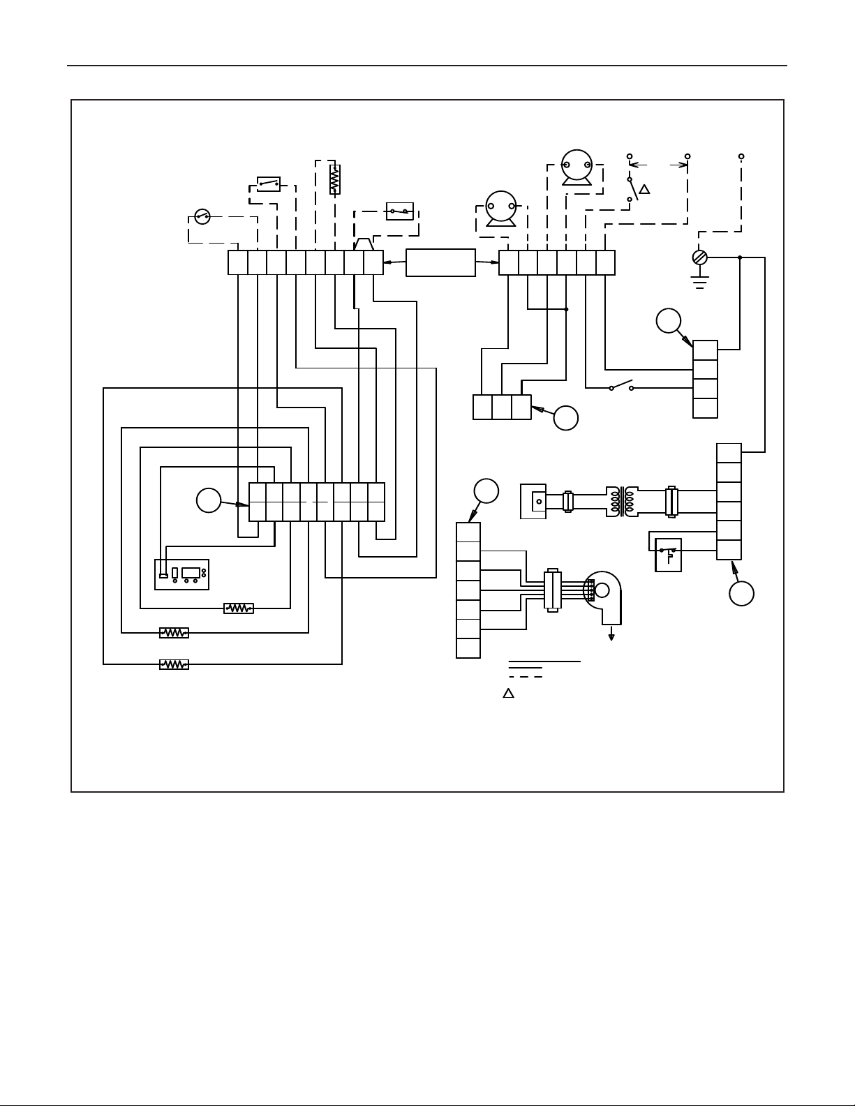
am (Figure 16a) boiler
required.
See boiler wir
ing diag
r
control (Figure16b) and ladder diagram (Figure 16c).
4. DOMESTIC HOT WATER TANK THERMOSTAT
A set of terminals are provided for connection of the DHW
tank thermostat (if used). (See wiring diagram Figure 16a).
5. OUTDOOR AIR SENSOR
A set of terminals are provided for connection of an outdoor
air sensor (if this method is used). (See wir
ing diagr
am
Figure 16a).
Mount on
The outdoor air sensor m
ust be a 12k ohm type
.
an outside wall, shielded from direct sunlight or flow of heat
or cooling form other sources. See instructions provided
with sensor.
6. LOW WATER CUTOFF
or connection of a LWCO. If
A set of ter
this de
minals are pro
vice is used, remove the factory installed jumper from
vided f
these terminals. (See wiring diagram Figure 16a).
Page 20
20
WIRE LEGEND:
1
M
CAUTION:
1
2
3
4
5
6
7
8
9
10
11 12
13 14 15
16
12
3
4
5
6
78
HN
H
N
HN
1
2
3
4
5
6
1
J5
J2
J6
J13
2
3
1
2
3
4
LABEL ALL WIRES PRIOR TO DISCONNECTION WHEN SERVICING CONTROLS.
PROPER OPERATION AFTER SERVICING".
WW
BL
R
BL
GY
DISPLAY
GY
W
G
BK
G
M
BK
G
W
G
ROUND
R
Y
PR
PK
B
R
GY
PR
BK
W
M
1
2
3
4
5
6
7
J9
BK
R
G
W
BL
1
W
W
W
BK
GY
GY
G
Y
G
Y
GY
FACTORY WIRED
FIELD WIRED, FIELD SUPPLIED
PROVIDE DISCONNECT MEANS & OVERLOAD PR OTECTION AS
REQUIRED.
IF ANY OF THE ORIGINAL WIRE AS SUPPLIEDWITH THE
APPLIIANCE MUST BE REPLACED, IT MUST BE REPLACED
WITH TYPE 105˚C OR ITS EQUIVALENT.
24V ROOM
T
HERMOSTAT
WIRING ERRORS CAN CAUSE IMPROPER AND DANGEROUS OPERATION.
"VERIFY
FIELD WIRING
TERMINALS
120V/24V
TRANSFORMER
DHW
C
IRCULATO R
(
IF USED)
DHW TANK
THERMOSTAT
(IF USED)
2
PIN
C
ONNECTOR
G
AS VALVE
HONEYWELL
VK8115
3 PIN
CONNECTOR
W
ATER HIGH
LIMIT
(WHITE CONNECTOR)
SUPPLY WATER SENSOR
(RED CONNECTOR)
R
ETURN WATER SENSOR
(BLUE CONNECTOR)
FLUE GAS SENSOR
(CLEAR CONNECTOR)
POWER
ON/OFF
S
WITCH
BOILER
CIRCULATO R
L
2
NEUTRAL
L1
HOT
120V
60HZ
1
2 K ohm
OUTDOOR
S
ENSER
(IF USED)
LOW WATER
C
UT OFF
(IF USED,REMOVE
7
-8 JUMPER)
5 PIN
C
ONNECTOR
COMBUSTION
B
LOWER
Bobcat Models B-120A and B-200A
Figure 16a. Schematic wiring diagram.
Page 21

Bobcat Models B-120A and B-200A
ARGUS CONTROL PHC794-S1
J5
J2
J
6
J9
FUSE
GROUND
S
PARK
CABLE
SPARK IGNITOR
J13
J12
T2
GND
NEUTRAL
HOT
L2
L1
120V/60HZ
120V
10V
120V
24V
M
M
DISPLAY
M
CHASSIS
GND
DISCONNECT
SWITCH
SPARK
ELECRODE
DHW CIRCULATO R
(IF USED)
BOILER
CIRCULATO R
COMBUSTION
BLOWER
BOILER ON/OFF
SWITCH
GAS
VALVE
SUPPLY WATER
SENSOR
RETURN WATER
SENSOR
FLUE GAS
SENSOR
OUTDOOR SENSER
(IF USED)
MICRO PROCESSOR
ON CONTROL BOARD
120V SECTION OF
CONTROL BOARD
LOW WATER CUT OFF
(IF USED) OR JUMPER
DHW THERMOSTAT
(IF USED) OR SENSOR
ROOM
THERMOSTAT
WATE R HIGH
LIMIT
21
Figure 16b. Boiler Control.
Figure 16c. Ladder wiring diagram.
Page 22
22
1
END
SWITCH
T
H-TR
MOTOR
2
T
TT T TT TT TT TT T TT
T
T
3
456
S
PAC E
HEATING
S
YSTEM
CIRCULATOR
END
S
WITCH
TH-TR
MOTOR
Z
ONE 2
THERMOSTAT
V8043E/F
END
S
WITCH
T
H-TR
MOTOR
ZONE 3
THERMOSTAT
V8043E/F
1 2 3 4 5 6 7 8
FIELD WIRING
T
ERMINALS
O
N BOILER
JUMPER
R
845A
R
ELAY
LI
L2
1
ZONE 1
THERMOSTAT
120V/24V
T
RANSFORMER
1
POWER SUPPLY, P ROVIDE DISCONNECT
MEANS AND OVERLOAD PROTECTION
AS REQUIRED.
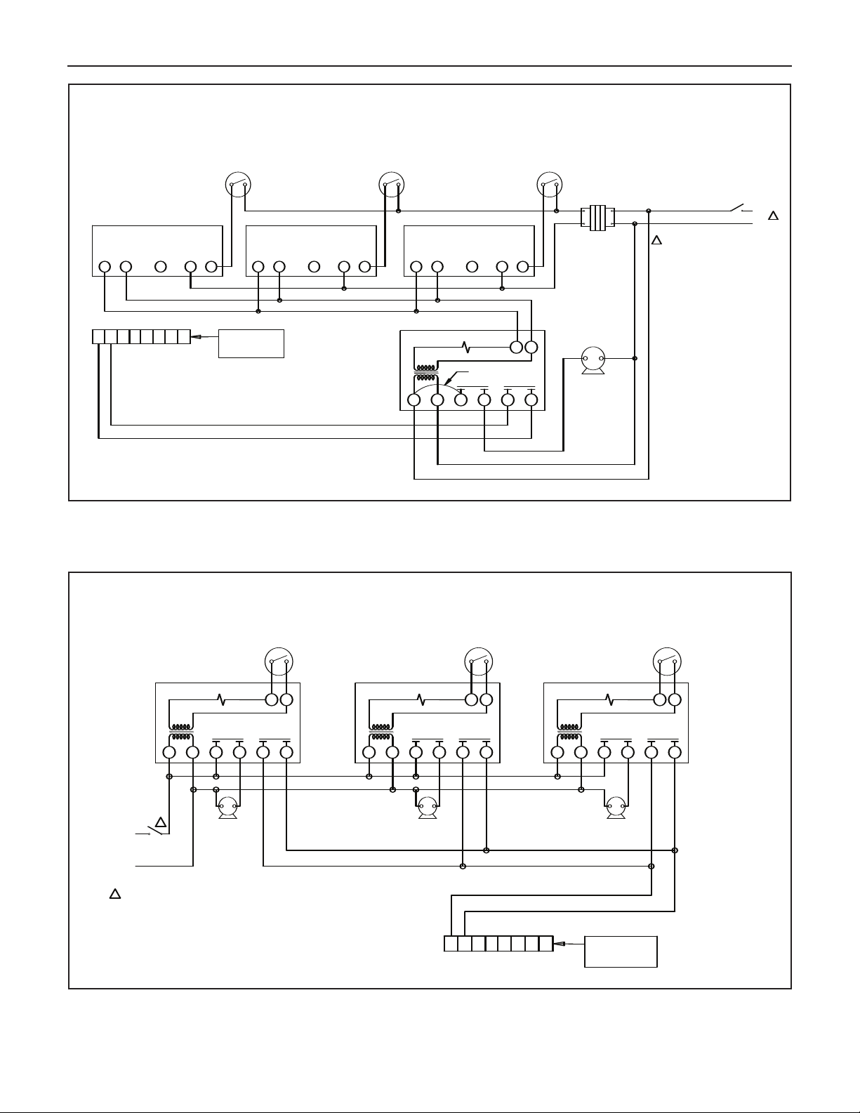
MULTIZONING OF "BOBCAT" BOILER;
ZONE VALVE SYSTEM USING V8043E/F ZONE VALVES AND R845A RELAY
DISCONNECT
SWITCH
V8043E/F
1 2 3 4 5 6 7 8
FIELD WIRING
TERMINALS
ON BOILER
1
2
TT
3456
TT TT
LI
L2
DISCONNECT
SWITCH
1
R845A
RELAY ZONE 3
CIRC.
ZONE 3
R845A
RELAY ZONE 2
CIRC.
ZONE 2
R845A
RELAY ZONE 1
CIRC.
ZONE 1
ZONE 3
THERMOSTAT
ZONE 2
THERMOSTAT
ZONE 1
THERMOSTAT
1
POWER SUPPLY, PROVIDE DISCONNECT
MEANS AND OVERLOAD PROTECTION
AS REQUIRED.
MULTIZONING OF "BOBCAT" BOILER;
PUMP ZONING SYSTEM USING R845A RELAY
1
23456
1
23456
Bobcat Models B-120A and B-200A
Figure 17a. Multizoning of Bobcat boiler; zone valve system.
Figure 17b.
Multizoning of Bobcat boiler;
pump zoning system using R845A rela
y
.
Page 23

Bobcat Models B-120A and B-200A
LI
L2
1
DISCONNECT
SWITCH
120V/24V
T
RANSFORMER
FIELD WIRING
TERMINALS
ON BOILER
C
IRC.
ZONE 3
ZONE 3
THERMOSTAT
1
P
OWER SUPPLY, PROVIDE DISCONNECT
MEANS AND OVERLOAD PROTECTION
AS REQUIRED.
MULTIZONING OF "BOBCAT" BOILER;
PUMP ZONING SYSTEM USING R882A/B RELAYS
C
IRC.
ZONE 2
R882A/B
R882A/B
ZONE 2
THERMOSTAT
C
IRC.
ZONE 1
R882A/B
ZONE 1
T
HERMOSTAT
120V/60HZ
1 2 3 4 5 6 7 8
1 2 3 4 5 6 7 8
1
2
TT
3
4
56
LI
L2
1
1
POWER SUPPLY, PROVIDE DISCONNECT
MEANS AND OVERLOAD PROTECTION
AS REQUIRED.
DISCONNECT
SWITCH
R845A
RELAY
THERMOSTAT
CIRCULATOR
FIELD WIRING
TERMINALS
ON BOILER
LI
L2
1
1
1 2 3 4 5 6 7 8
POWER SUPPLY, PROVIDE DISCONNECT
MEANS AND OVERLOAD PROTECTION
AS REQUIRED.
DISCONNECT
SWITCH
THERMOSTAT
CIRCULATOR
R 882A/B
RELAY
120 V / 24 V
TRANSFORMER
FIELD WIRING
TERMINALS
ON BOILER
23
Figure 17c. Multizoning of Bobcat boiler; pump zoning system using R882A/B relays.
Figure 17d. Single zoning of Bobcat boiler; pump
zoning system using R845A relay.
Figure 17e. Single zoning of Bobcat boiler; pump zoning system using R882A/B relay.
Page 24

24
Bobcat Models B-120A and B-200A
WATER PIPING
1. Connection of system to boiler:
rimary/secondary piping of the system is recommended, to
P
nsure the proper flow through the boiler. (See Figures 20
e
through 22). The boiler loop piping must be the same
diameter as the water outlet (supply) and inlet (return) piping
connections provided on the boiler, particularly on longer
loops. See page 2 for piping connection size.
2. Circulator Pumps:
The boiler loop piping must utilize the Taco 0011 circulator for
-120 and 0013 for B-200 that is supplied with the boiler, to
B
nsure the proper flow through the boiler. Refer to Figure 19
e
for the boiler water side pressure drop and Table 2a and 2b
for the recommended pump models for the domestic hot
water system. Install the pumps in the orientation shown in
Figures 20 through 22.
3. Relief Valve(supplied with boiler):
Tee the relief valve into the boiler water outlet (supply) piping
as close to the water outlet (supply) connection as possible.
(See Figure 18). The relief valve’s discharge piping must be
the same size or larger than the relief valve’s outlet, and must
terminate 6” minimum from floor with a plain (no threads) end.
Place a bucket under pressure relief valve discharge. Make
sure discharge is always visible. DO NOT hard-pipe to drain
piping, or any place where freezing could occur. No shut-off
valve is permitted between the relief valve and boiler, or in the
discharge line.
4. Air Control System:
An appropriately sized diaphragm-type expansion tank must
be used to control the system pressure. See boiler volume
data on page 2, and the recommended location in Figures 20
through 22. An air vent is recommended to be installed on an
air separator in close proximity to the expansion tank.
5. Cold Water Fill:
A pressure reducing (fill) valve, with a shut-off valve upstream
of it, should be installed in close proximity of the expansion
tank. (See Figures 20 through 22). Use a back flow check
valve in the cold water supply as required by local codes.
w Water Cutoff:
6. Lo
On a hot water boiler installed above radiation level, the boiler
must be provided with a low water cutoff device at the time of
installation by the installer (see Figure 18 for piping
arrangement).
7. Water Treatment and Freeze Protection:
A good water treatment program will not only extend the
useful life of this boiler but it will also save much of the time
nd expense of repairs made necessary by preventable
a
ccurrences. A reputable water treatment company should be
o
consulted to evaluate and determine the best overall
treatment program for your boiler equipment.
The heat exchanger is made of aluminum, so the system
water must be maintained between 7.0 and 8.5 PH level.
horoughly flush the system, before connecting the boiler, to
T
emove any sediment or glycol.
r
Anti-freeze is sometimes used in hydronic systems to
protect against freez-up in the event of power failure or
boiler shut down in the cold winter.
(Propyleneglycol with Pro-Tek 922 inhibitor) by Rhomar
Water Management, Inc.
instructions for proper application and proper mixture for
um ambient temperature.
minim
other than that supplied by Slant-Fin or specifically
approved and/or recommended for use by Slant-Fin
will void this warranty.
Never use Ethylene Glycol as it is toxic to humans.
Never use any types of automotive or standard gylcol freeze
protection fluids.
8. Piping a heating - cooling system to a water boiler and
chiller:
Figure 22 illustrates a method of piping a heating-cooling
system to a water boiler and a chiller. Hand valves (shown)
or automatic valves must be installed to prevent circulation
of chilled water in the boiler or hot water in the chiller.
The air control system and pressure control system must
operate with chiller only, or the boiler only, being valved to
the piping system. Separate control devices on the boiler
and chiller may be used, or a single set of air and pressure controls on the common piping may be preferred.
If the boiler is used to supply hot water to heating coils in
air handling units, flow control valves or other devices
must be installed to prevent gravity circulation of water in
the coils during the cooling cycle.
Follow the manufacturer’s
Use RhoGard
y use of anti-freeze
An
Page 25

Bobcat Models B-120A and B-200A
W
AT ER OUTLET
PIPING,TO
REST OF SYSTEM
LOW WAT ER CUTOFF MANIFOLD
(IF LWCO UTILIZED)
PROBE-TYPE LOW WATER CUTOFF
(IF REQUIRED)
1" X 1" X 3/4"
NPT TEE
WAT ER OUTLET (SUPPLY)PIPE,
1" NPT MALE
WAT ER INLET
(RETURN) PIPE,
1" NPT MALE
RELIEF
VALVE
DISCHARGE
PIPING
PRESSURE RELIEF VALVE
(SUPPLIED WITH BOILER)
3/4" NPT
STREET ELBOW
25
Figure 18. Relief Valve and Low Water Cutoff Installation
Page 26
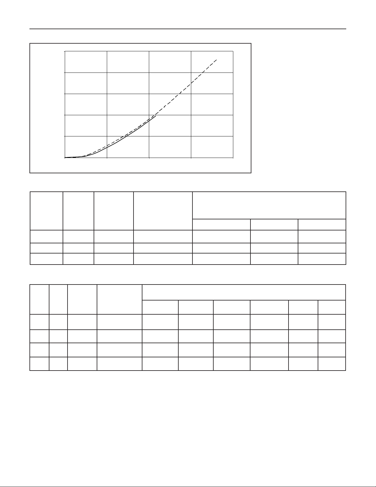
26
0
5
10
15
20
25
0
5 10 15 20
Head
(feet w.c.
)
Flow Rate (GPM)
B-200
B
-120
Figure 19. Boiler water side pressure drop
Bobcat Models B-120A and B-200A
Flow
Rate
(gpm)
Temp
Rise
(˚F)
Boiler
Head
Loss
(Feet w.c.)
Domestic Water
Tank Piping
Head Loss **
(Feet w.c.)
10.8 20˚ 10.0' 3.0'
Available Head Capability Left for Various Model
Circulators to Overcome DHW Tank Head Loss
(Feet w.c.) ***
Taco 0012 Taco 0014 Taco 0011
Not Recommended
4.0' 9.5'
7.2 30˚ 5.0' 2.5' 5.0' 10.5' 17.5'
5.4* 40˚ 3.0' 1.5' 8.5' 14.5' 23.5'
Table 2a. Recommended pump models for domestic hot water tank piping to the Bobcat model B-120 boiler.
Flow
Rate
(gpm)
Temp
Rise
(˚F)
Boiler
Head
Loss
(Feet w.c.)
Domestic
Tank Piping
Head Loss **
(Feet w.c.)
18.0 20˚ 23.0' 4.0'
14.5 25˚ 16.5' 3.5'
Water
Taco 0011 Taco 0013
Not
Recommended
Not
Recommended
Available Head Capability Left for Various Model
Circulators to Overcome DHW Tank Head Loss (Feet w.c.) ***
aco
T
1400-20
s
Not
Recommended
Not
Recommended
(2 in Series)
Taco 0011
s
3.0' 13.0'
(2 in Series)
Taco 0013
3.5' 17.0' 27.0' 6.0' 15.5'
1400-45
s
12.0 30˚ 12.5' 3.0' 5.5' 10.5' 26.5' 36.5' 12.0' 21.5'
9.0 * 40˚ 7.5' 2.5' 14.0' 18.0' 38.0' 46.0' 19.5' 28.5'
aco
T
6.5'
s
Table 2b. Recommended pump models for domestic hot water tank piping to the Bobcat model
Notes:
This is the minimum flow rate recommended for each of the boiler models.
*
** Domestic water tank piping head is based on 1” inside diameter piping and full port valves.
*** Refer to the DHW Tank Manufacturer’s water flow rate requirements and associated pressure drop head loss, to select
the appropriate circulator.
s If 2 circulators are specified, the
circulator(s) m
ust be supplied through an appropr
ust be piped in ser
y m
ies in order to pro
iate rela
y to protect the boiler control’
vide the head capacity sho
s fuse
B-200 boiler.
P
wn.
.
er to
w
o
Page 27

Bobcat Models B-120A and B-200A
FROM REST
OF SYSTEM
TO REST
OF SYSTEM
BOBCAT BOILER
ADDITIONAL
ZONES
SPAC E HEAT
ZONE #1
ISOLATION
VALVE
ISOLATION
VALVE
F
LOW CHECK
V
ALVE
ZONE
C
IRCULATOR
D
O NOT EXCEED
1
2" APART
AIR VENT
AIR SEPARATOR
ISOLATION
V
ALVE
MAKE UP
WATE R
SUPPLY
SHUTOFF
VALVE
PRESSURE
REDUCING
VALVE
BACK FLOW
P
REVENTOR
(
IF REQUIRED)
PURGE/
DRAIN
V
ALVE
ISOLATION
VALVE
BOILER LOOP
C
IRCULATOR
(SUPPLIED WITH
THE BOILER)
FLOW CHECK
VALVE
HOT WATER
OUTLET
COLD
INLET
WATE R
SHUTOFF
VALVE
DRAIN VALVEDRAIN VALVE
DOMESTIC
HOT WATER
TANK
T + P
RELIEF
VALVE
BOILER WATER
OUTLET (SUPPLY)
RELIEF
VALVE
FLOW CHECK
VALVE
DHW
CIRCULATOR
ISOLATION
VALVE
E
XPANSION TANK
(DIAPHRAM TYPE)
BOILER WATER
INLET (RETURN)
27
Figure 20. Zoning with circulators.
Page 28
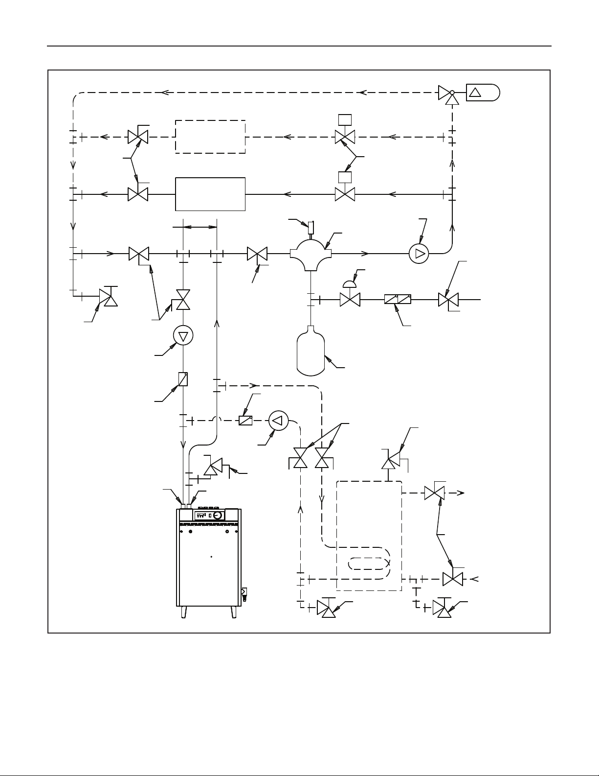
28
P
SYSTEM
CIRCULATOR
D
IFFERENTIAL
P
RESSURE BYPASS
VALVE (IF USED)
BOBCAT BOILER
ADDITIONAL
ZONES
SPAC E HEAT
ZONE #1
I
SOLATION
V
ALVE
ZONE
VALVE
DO NOT EXCEED
12" APART
A
IR VENT
A
IR
S
EPARATOR
I
SOLATI ON
VALVE
MAKE UP
WATE R
SUPPLY
SHUTOFF
VALVE
P
RESSURE
R
EDUCING
VALVE
BACK FLOW
PREVENTOR
(IF REQUIRED)
PURGE/
D
RAIN
VALVE
ISOLATION
V
ALVE
BOILER LOOP
CIRCULATO R
(SUPPLIED WITH
THE BOILER)
FLOW CHECK
VALVE
HOT WATER
OUTLET
COLD
INLET
WATE R
SHUTOFF
VALVE
DRAIN VALVEDRAIN VALVE
DOMESTIC
HOT WATER
TANK
T + P
RELIEF
VALVE
BOILER WATE R
OUTLET (SUPPLY )
RELIEF
VALVE
FLOW CHECK
VALVE
DHW
CIRCULATOR
ISOLATI ON
VALVE
EXPANSION TANK
(DIAPHRAM TYPE)
BOILER WATE R
INLET (RETURN)
Bobcat Models B-120A and B-200A
Figure 21. Zoning with zone v
alves.
Page 29
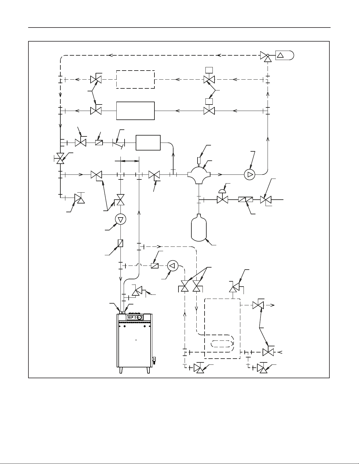
Bobcat Models B-120A and B-200A
P
SYSTEM
CIRCULATOR
DIFFERENTIAL
PRESSURE BYPASS
VALVE (IF USED)
BOBCAT BOILER
ADDITIONAL
ZONES
SPAC E HEAT
ZONE #1
ISOLATION
VALVE
ZONE
V
ALVE
D
O NOT EXCEED
12" APART
A
IR VENT
AIR
SEPARATOR
ISOLATI ON
VALVE
MAKE UP
WATE R
SUPPLY
SHUTOFF
VALVE
PRESSURE
R
EDUCING
VALVE
BACK FLOW
PREVENTOR
(
IF REQUIRED)
PURGE/
DRAIN
VALVE
ISOLATION
VALVE
B
OILER LOOP
C
IRCULATO R
(SUPPLIED WITH
T
HE BOILER)
FLOW CHECK
VALVE
HOT WATER
OUTLET
COLD
INLET
WATE R
SHUTOFF
VALVE
DRAIN VALVEDRAIN VALVE
DOMESTIC
HOT WATER
TANK
T + P
RELIEF
VALVE
BOILER WATE R
OUTLET (SUPPLY )
RELIEF
VALVE
FLOW CHECK
VALVE
DHW
CIRCULATOR
ISOLATI ON
VALVE
EXPANSION TANK
(DIAPHRAM TYPE)
BOILER WATE R
INLET (RETURN)
FLOW CHECK
VALVE
I
SOLATION
V
ALVE
WATE R
CHILLER
UNIT
STRAINER
B
ALANCING
V
ALVE
29
Figure 22. Piping a heating-cooling system to the boiler and a chiller.
Page 30

30
OPERATING INSTRUCTIONS
I. FILLING AND VENTING WATER SYSTEMS
Bobcat Models B-120A and B-200A
. While “t” is blinking, DHW tank temperature may be
3
et to desired temperature (if tank is equipped with
s
sensor). The setting range is between 104˚ to 185˚F.
. Fill the system with water. Vent or purge of air.
A
B. Fire the boiler as soon as possible (see following warning
and instructions) and bring water temperature in the
system.
C. Vent air and add water as needed to achieve operating
pressure on boiler gauge. Pressure must be between
pproximately 12 psi (cold water) and 25 psi at water
a
emperature setting of high limit control, for boilers
t
equipped with 30 psi relief valves. Boilers rated for a higher
pressure and equipped with a matching relief valve may
operate at a higher pressure, but no higher than 5 psi
w the relief valve opening pressure.
belo
D. Check for and repair any leaks before placing system in
service.
BEFORE FIRING BOILER, make these checks:
Before firing boiler, review the “Boiler Control and Display
Features” section of this manual. Understanding the features and
programming the applicable parameters is essential for setting up
the boiler to operate properly on the heating system it is installed
on.
1. System is full of water. Air is vented or purged.
2. Relief valve is installed in accordance with ASME Boiler
and Pressure Vessel Code, Section IV. Valve opening is
not closed or reduced in size.
3. Venting is installed according to instructions under “FLUE
GAS VENTING REQUIREMENTS”.
4. View actual boiler supply & return water temperature, domestic hot water tank temperature (if tank
equipped with sensor), flue temperature and outside
temperature (if outside sensor is used) on
“Temperature Display” by selecting 1, 2, 3, 4, or 5 on
Mode Display”.
“
• These numbers are steady on display and are
not settable.
• All sensor inputs to the control must be
connected to a 12k ohm sensor.
C.
Viewing and changing system setting:
A trained, experienced service technician or installer should
perform following adjustments. See table 5 for details.
1. Space heating and DHW post pump time may be
changed.
2. Space heating and DHW modes may be chosen.
3. Weather compensation slope and set point temperature
may be changed (if outside sensor is used).
(See Figure 24 for graph).
4. Read actual blower RPM
5. Adjust blower RPM for high and low input adjustment.
6. Read flame current in micro amp.
7. Run boiler on high, low or ignition input steady for 20
minutes for test purposes.
Display and push buttons:
D.
4. All wiring is completed, following applicable wiring
diagrams.
5. Using soap solution, check for gas leaks in all gas piping
from meter to boiler gas supply pipe
flame.
II. BOILER CONTROL AND DISPLAY FEATURES
(See Figure 23)
A. Boiler Operation Status:
“Mode Display” shows status of boiler operation
(see table 3).
.
B
View and Changing Temperatures:
Setting boiler supply w
temperature (see table 4).
Press “Select” button for viewing following different modes
on “Mode Display”
1. While “c” is blinking, boiler supply water temperature
for space heating may be set to desired temperature
The setting r
“d”
While
2.
for DHW may be set to desired temperature. The
setting range is between 104˚ to 185˚F.
ater temperature and water tank
ange is betw
linking, boiler supply w
is b
DO NOT use open
.
een 90˚ to 185˚F
ater temper
.
ature
1. Reset - Used to clear a Lock out error (indicated with an
“A” in the “Mode Display”).
Select - Used to scroll through the modes in the “View
2.
and Changing Temperatures” and “Viewing and Changing
System Setting” men
Enter - Used to store values that are changed in the “View
3.
and Changing Temperatures” and “Viewing and Changing
System Setting” menus.
4.
Up- Used to increase v
Temperatures” and “Viewing and Changing System
Setting” menus.
wn -
5.
Do
Changing Temperatures” and “Viewing and Changing
System Setting”
Used to decrease v
us.
alues in the “View and Changing
alues in the “View and
.
us
men
Page 31

Bobcat Models B-120A and B-200A
*
"MODE" DISPLAY
"TEMPERATURE" DISPLAY (3 DIGITS)
"UP" PUSH BUTTON
"DOWN" PUSH BUTTON
"ENTER" PUSH BUTTON
"SELECT" PUSH BUTTON
"RESET" PUSH BUTTON
"BURNER STATUS"
STEADY DOT = BURNER ON
BLINKING DOT = BURNER OFF
Table 3
Table 3
Table 3
Table 3
Table 3
Table 3
Table 1
Table 3
31
Figure 23. Display Board
Table 3
BOBCAT BOILER DISPLAY BOARD
“Boiler Operation Status”
MODE
DISPLAY
Reset button must be pressed to resume normal operation.
DESCRIPTION & TEMPERATURE DISPLAY
Boiler is on stand-by mode.
Temperature display shows supply water Temp.
Space heating mode.
Temperature display shows supply water Temp.
Domestic hot water mode.
Temperature display shows supply water Temp.
Frost protection mode. **
Temperature display shows supply water Temp.
Lockout (Alarm) condition.
ature Display indicates the lockout code
emper
T
Error Condition. *
Temperature display indicates the error code.
Warning Condition. ***
Temperature display indicates the error code.
NO
TE:
Blinking dot on
Steady dot indicates b
Error m
*:
The boiler loop circulator is energiz
**:
Error m
***:
the “Reset” button is not required.
ust be corrected to resume boiler oper
ust be corrected to resume DHW oper
“Mode Displa
ner is on.
ur
indicates activ
y”
e heating control, b
ation.
ed, if the boiler w
ation.
Pressing the
ater temper
Space heating not aff
urner off.
“Reset”
ature drops belo
utton is not required.
b
.
w 50˚F
Pressing
ected.
Page 32

32
T
able 1
T
able 3
Table 1
Table 3
T
able 1
T
able 3
T
able 3
Table 3
Table 3
T
able 3
Table 3
Bobcat Models B-120A and B-200A
Table 4
VIEWING AND CHANGING TEMPERATURES
Press “SELECT” button for viewing different modes on “MODE DISPLAY”
ODE
M
DISPLAY
Space heating supply water temperature could be changed by
blinking
Domestic hot water supply temperature could be changed by
blinking
blinking
DESCRIPTION & TEMPERATURE DISPLAY
pressing “Up/Down” button. Settable from 90˚F to 185˚F
(steps of 1 F). The default value is 176˚F.
Press “Enter” button to store.
(see note 1)
pressing”Up/Down” button. Settable from 104˚F to 185˚F
(steps of 1 F). The default value is 176˚F.
Press “Enter” button to store.
(see note 2)
Domestic hot water tank temperature could be changed by
pressing “Up/Down” button. Settable from 104˚F to 160˚F
(steps of 1 F). The default value is 140˚F.
Press “Enter” button to store.
(see note 3)
NOTE:
Temperature display shows actual supply water temperature.
Temperature display shows actual return water temperature.
Temperature display shows actual DHW tank temperature.
(if the water tank is equipped with sensor).
Temperature display shows actual flue gas temperature.
Temperature display shows actual outside temperature.
(if outdoor sensor is used)
or space heating mode “0”
1- F
2- For DHW mode “2” (storage tank with Aquastat)
3- For DHW mode “1” (storage tank with sensor)
(boilers not utilizing outdoor sensor))
Page 33

Bobcat Models B-120A and B-200A
Table 3
Table 3
Table 3
Table 3
Table 3
VIEWING AND CHANGING SYSTEM SETTING - Table 5
“To change system setting or perform system test”
he menu is accessed by pressing and holding “SELECT” and “ENTER” buttons for 10 seconds. To change
T
system setting: Press “UP or DOWN” button, then press “ENTER”
WARNING: Only a trained, experienced service technician or installer should use this table.
33
MODE DISPLAY
*
*
*
*
*
*
*
DESCRIPTION
Changing space heating post pump time. Settable from 10 to 900 seconds.
(steps of 10 seconds). The default value is 30 seconds.
Changing DHW post pump time. Settable from 1 to 255 seconds.
(steps of 1 seconds). The default value is 15 seconds.
hanging space heating control mode
C
0: Thermostat only (default) - boiler without outdoor sensor
: Outside sensor and Thermostat
1
Outside sensor only
2:
3: Permanent heat demand (boiler circulator always on)
C
hanging domestic hot water (DHW) mode
0: No DHW
1: Storage tank with sensor
2: Storage tank with thermostat (default value)
Plate heat e
3:
Changing DHW or space heating priority mode
0: DHW priority (no time limit)
1: Space heating priority (no time limit)
2: DHW priority for limited time (default)
3: Space heating priority for limited time
Changing priority limited time. Settable from 20 to 80 minutes.
Boiler model selection, value is 0 for model B-120 and 4 for model B-200
xchanger
The default value is 30 minutes.
**
**
*
*
*
*
*
*
*
*
Boiler model confirmation, value is 0 for model B-120 and 4 for model B-200
Weather compensation supply water reference temperature
(space heating mode 1 or 2). Settab
Changing compensation slope (space heating mode 1 or 2).
Changing weather compensation set point (space heating mode 2 only).
Displa
Change blower RPM for high input (steps of 30 RPM, limit +/- 480 RPM).
Change blower RPM for low input (steps of 30 RPM, limit +/- 120 RPM).
Settable from 32˚F to 122˚F (steps of 1˚F).
y sho
System test – Display shows flame current
The def
Settable from 0.1 to 5.0 (steps of 0.1).
The default value is 1.0.
The default value is 68˚F.
ws blower RPM (mutiply reading by 10 for actual RPM)
Display shows flame current in micro amps
0: System test off
L: Steady low input (20 minutes)
I: Steady ignition input (20 minutes)
H: Steady high input (20 minutes)
le from 16˚F to 122˚F (steps of 1 F).
alue is 86˚F.
ault v
Not Utilized
NOTE: *: Alternating **: Steady
Page 34
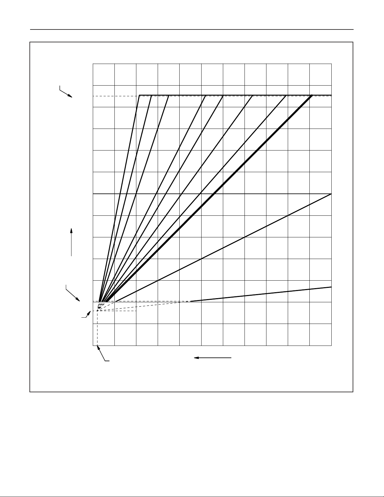
34
70
70 60 -20-10 -3001020304050
Outdoor Temp. (°F)
Water
Supply
Target Temp.
(°F)
185 °F
140
150
130
190
180
170
160
120
110
100
80
90
2
00
S
l
o
p
e
=
4
.
0
S
l
o
p
e
=
3
.
0
S
l
o
p
e
=
0
.
1
(
m
i
n
.
)
S
l
o
p
e
=
2
.
0
S
l
o
p
e
=
0
.
5
S
l
o
p
e
=
1
.
2
S
l
o
p
e
=
5
.
0
(
m
a
x
.
)
-40
S
l
o
p
e
=
1
.
5
S
l
o
p
e
=
1
.
0
(
d
e
f
a
u
l
t
)
S
l
o
p
e
=
1
.
8
Ma
ximum
water target
temp.
Water
reference
temp.(default
of86°F)
Minimum
watertarget
temp.
68°F
Bobcat Models B-120A and B-200A
Figure 24. Space Heating mode with outside sensor water set point graph.
Page 35

Bobcat Models B-120A and B-200A
GAS SUPPLY SHUTOFF VALVE
I
N "OPEN" POSITION
GAS SUPPLY SHUTOFF VALVE
I
N "CLOSED" POSITION
TURN 90˚
TO CLOSE
T
URN 90˚
TO OPEN
III. INITIAL START
Safe lighting and other performance criteria were met when testing
various gas manifold and control assemblies used on the Bobcat
B-120 and B-200 boilers under the ANSI Z21.13 - latest edition.
Instructions
Follow the lighting instructions in this manual.These instructions
are also attached to the boiler.
. Use only your hand to turn the gas supply shut-off valve.
C
Never use tools. If the supply shut-off valve will not turn by
hand, don’t try to repair it, call a qualified service technician.
Force or attempted repair may result in a fire or explosion.
D. DO NOT use this appliance if any part has been under
water. Immediately call a qualified service technician to
inspect the appliance and to replace any part of the
control system and any gas control which has been under
water.
OPERATING INSTRUCTIONS
STOP! Read the safety information above.
1.
2. Set the thermostat to lowest setting.
3. Turn off all electric power to the appliance.
4. This appliance is equipped with an ignition device which
automatically lights the burner. DO NOT try to light the
burner by hand.
35
Figure 25. Gas supply shutoff valve operation.
SAFETY INFORMATION
For Your Safety Read Before Operating
WARNING: If you do not follow these instructions exactly, a fire
or explosion may result causing property damage, personal
injury or loss of life.
This appliance does not have a pilot. It is equipped with
A.
an ignition device which automatically lights the burner.
DO NOT try to light the burner by hand.
BEFORE OPERATING smell all around the appliance area
.
B
for gas. Be sure to smell next to the floor because some gas
.
vier than air and will settle on the floor
is hea
WHAT TO DO IF YOU SMELL GAS:
• DO NOT try to light any appliance.
• DO NOT touch any electric switch: DO NOT use any
phone in your building.
• Immediately call you gas supplier from a neighbor’s
phone. Follow the gas supplier’s instructions.
•
If you cannot reach your gas supplier, call the fire
tment.
depar
5. Open the gas supply shut-off valve, by turning the handle to
be parallel to the gas piping (See Figure 25).
6. Wait five (5) minutes (longer for propane) to clear out any
gas, then smell for gas, including near the floor. If you then
smell gas, STOP! Follow “B” in the safety information
above on this page. If you don’t smell gas, go to next step.
7. Turn on all electric power to the appliance.
8. Set thermostat to desired setting.
If the appliance will not operate, follow the instructions
“To Turn Off Gas to Appliance” and call your service
technician or gas supplier.
TO TURN OFF GAS TO APPLIANCE
1. Set thermostat to lowest setting.
n off all electric po
ur
T
2.
be perf
ormed.
er to the appliance if ser
w
vice is to
3. Close the gas supply shut off valve, by turning the handle
to be per
pendicular to the gas piping. (See Figure 25).
Page 36

36
Bobcat Models B-120A and B-200A
BOBCAT BOILER MODELS B-120 and B-200 SEQUENCE OF OPERATION
THERMOSTAT CALLS FOR HEAT
CIRCULATOR(S) ON
COMBUSTION BLOWER ON
(AT MEDIUM SPEED)
CONTROL LOCKOUT
DISPLAY SHOWS
ERROR “A 33”
CONTROL LOCKOUT
DISPLAY SHOWS
ERROR “A 03”
NO
NO
BLOWER SPEED CONFIRMED?
YES
5 SECOND PRE-PURGE
TRIAL FOR IGNITION - 6 SECONDS
SPARK IGNITOR ENERGIZED
GAS VALVE OPENS
WATER HIGH LIMIT CLOSED?
YES
GAS VALVE REMAINS OPEN
FOR 4 SECONDS
PERIOD
NO
3 TRIALS FOR
IGNITION
WITH NO FLAME SENSED?
2 TIMES RETRIALS
FOR IGNITION
CONTROL LOCKOUT
DISPLAY SHOWS
ERROR “A 01”
YES
SPARK IGNITOR DE-ENERGIZED
NO
FLAME SIGNAL SENSED?
YES
GAS VALVE REMAINS OPEN. CONTROL
CONTINUOUSLY MONITORS
, HIGH LIMIT, WATER
T
THERMOST
SENSORS, BLOWER SPEED, FLAME
SIGNAL, AND LWCO (IF USED).
THERMOST
10 SECOND
15 SECOND
A
CALL FOR HEAT ENDS
T
A
CLOSES
VE
AL
V
GAS
POST PURGE.
WER
BLO
CIRCULATOR POST PURGE.
GAS VALVE CLOSED.
BLOWER POST PURGE
10 SECONDS.
Page 37

Bobcat Models B-120A and B-200A
37
IV. CHECK COMBUSTION AND FUEL INPUT RATE
A. Remove the boiler jacket front panel, by turning the 2
black screws 1/4 turn to the open position. Lift off panel.
. Start and run the burner at the high firing rate, by using the
B
“System Test” mode in the “View and changing system
setting” menu. Refer to Table 5 on page 32.
1. Measure the CO, and CO2of the flue gas. A
flue sample port is provided in the vent pipe (See
Figure 2 on page 3). The CO should not exceed 100
ppm, when the combustion is correct. The CO2
hould be in the range listed in Table 6.
s
2. If the CO2is not within the range specified for that
gas type at the high firing rate, then adjust the venturi
throttle to the nominal value shown in Table 6. Turn
the throttle clockwise to decrease the CO
the throttle counter-clockwise to increase the CO
value. See Figure 26.
3. Once the correct combustion is confirmed at the
high firing rate, check the fuel input rate on the
gas meter.
BTUH INPUT = cu. ft. metered in 3 minutes x
heating value of the gas* x 20
* The higher heating value of the gas can vary for
different localities. Consult the gas supplier for this
value in BTU/cu.ft.
value.Turn
2
2
C. In the “System Test” mode in the “View and Changing
System Setting” menu, use the “down” push button to
switch to the low firing rate. Refer to Table 5 on
page 32.
1. Measure the CO and CO2of the flue gas. The CO
hould not exceed 30 ppm, when the combustion
s
s correct. The CO
i
isted in Table 6.
l
2. If the CO2is not within the range specified for that
gas type at the low firing rate, then adjust the gas
valve offset to the nominal valve shown in Table 6.
(See Figure 26) for the location of the offset
adjustment. Remove the cap that covers the offset
screw.
Turn the offset clockwise to increase the CO2value.
Turn the offset counter-clockwise to decrease the
CO
value. Replace the offset cap when adjustment
2
is complete
3. Once the correct combustion is confirmed at the
low firing rate, check the fuel input rate of the gas
meter. BTUH Input = cu. ft. metered in 3 minutes x
heating valve of the gas * x 20.
.
hould be in the range
s
2
4. If the fuel input is not at the rate specified on page 2
at the high firing rate, then the blower speed
should be adjusted to attain the specified input rate.
This can be done by using the “Change blower RPM
for high input” mode in the “View and changing
System Setting” menu. Refer to Table 5 on page 32.
Increasing the blower rpm will increase the fuel input
rate, and decreasing the blower rpm will decrease the
fuel input r
Propane
Fuel
Nat.
Gas
ate.
CO
Firing
Rate
min. nom. max.
High 8.7% 9.0% 9.3%
Low 7.7% 8.0% 8.3%
High 10.2% 10.5% 10.8%
Low 9.2% 9.5% 9.8%
2
Figure 26. Gas valve and venturi adjustment.
Table 6. Combustion values for Natural Gas and Propane.
Page 38

38
Bobcat Models B-120A and B-200A
4. If the fuel input is not at the rate specified on page 2
at the minimum firing rate, then the blower speed
should be adjusted to attain the specified input rate.
This can be done by using the “Change blower RPM
for low input” mode in the “View and Changing
System Setting” menu. Refer to Table 5 on page 32.
ncreasing the blower rpm will increase the fuel input
I
rate, and decreasing the blower rpm will decrease the
fuel input rate.
D. Exit the “System Test” mode, once the combustion and fuel
input rate has been checked and adjusted, if necessary.
Refer to Table 5 on page 32.
V. SAFETY CHECK
A. Check for gas leaks:
Using soap solution, check for gas leaks from meter to gas
valve including all pipes and fittings and gas valve
connections. Use liquid soap solution for all gas testing. DO
NOT use open flame.
Thermostat Test:
.
B
Set thermostat setting to low enough to end call for heat.
Gas valve should close and burner should stop firing.
A. LOCKOUT ERRORS: Indicated by an “A” in the mode display. The reset button must be pressed to clear the error
and retry operation. The temperature display shows the error code.
Blower and circulator pump should go into a post purge,
then shut off.
Control Safety Shutdown test:
C.
With the burner firing, disconnect the spark cable from the
spark ignitor. Gas valve should close and burner should
top firing. The boiler will try for ignition three times after
s
this, then should lock out with an “A 01” error shown on the
display. Reconnect the spark cable to the spark ignitor, and
press the “Reset” button to return to normal operation.
VI. DIAGNOSTIC ERROR CODES
WARNING:
should perform troubleshooting. Turn off all electric power to the
boiler before service.
Only a trained, experienced service technician
ERROR CODE INDICATION REMEDY
Check for steady sparking at electrodes. If spark not
steady - check spark gap to be .125”, clean or replace
spark ignitor, check power supply voltage and grounding.
If spark is steady - check for proper gas supply pressure.
01
Ignition Failure - 3 unsuccessful
ignition attempts in a row.
Check combustion, if able to ignite, or replace gas valve.
Check for proper combustion, at both max. and min.
02
Flame Failure - 3 losses of flame
signal dur
ing one demand.
input fir
specified in Table 6 on page 36, clean or replace spark
ing rates. If combustion is within the range
ignitor, check power supply voltage and grounding.
Check to see if the water outlet temperature reaches
03
Water High Limit Open
203˚F. If it does, replace the water outlet 12k ohm
sensor. If it does not, replace the water high limit switch.
04,
05, 09, 10,
12, 13, 14, 15,
16, 18, 32
Control Failure
Replace control board. Make sure the proper boiler
model selection and confirmation code is entered.
Table 5 on page 32.
See
If a flame is still observed after a call for heat is stopped,
If the burner seems to be shutting
19, 20
Flame Detected at
Wrong Time
replace the gas v
alve
.
down properly, replace the spark ignitor.
33
an Failure - RPM error
F
Check wire harness connections going to the blower.
Replace blower.
Page 39

Bobcat Models B-120A and B-200A
B. BLOCKING ERRORS: Indicated by an “E” in the mode display. Operation is automatically restored, once the
condition returns to normal or is fixed. The temperature display shows the error code. Pressing the “Reset”
utton is not required.
b
ERROR CODE INDICATION REMEDY
Check wire harness connections going to the
01
02
03
Water Outlet Sensor Open
Water Inlet Sensor Open
Flue Gas Sensor Open
sensor.
Replace the sensor.
Check wire harness connections going to the
sensor.
Replace the sensor.
Check wire harness connections going to the
sensor.
Replace the sensor.
39
11
12
13
19, 42, 45,
46, 47, 48
20
21
22
24
Water Outlet Sensor Shorted Replace the sensor.
Water Inlet Sensor Shorted Replace the sensor.
Flue Gas Sensor Shorted Replace the sensor.
Replace control board. Make sure the proper
Control Failure
Flame Detected at Wrong Time
Polarity Error Reverse the hot and neutral power supply wires.
Frequency Error
Earth Connection Faulty Check grounding of control and boiler chassis.
boiler model selection and confirmation code is
entered. See Table 5 on page 32.
If a flame is still observed after a call for heat is
stopped, replace the gas valve, If the burner
seems to be shutting down properly, replace the
spark ignitor.
Check power supply frequency to be 60 hz,
certain power supplies may not provide the
proper frequency
.
contin
ued on pa
g
e 39
Page 40

40
continued from page 38
ERROR CODE INDICATION REMEDY
30
31
32
Excess Flue Temperature
Low Water Cutoff Error
Excess Water Inlet Temperature
Bobcat Models B-120A and B-200A
Check flue gas temperature, at the maximum firing
rate and high water temperature. If the flue gas
temperature reaches 212˚F, check the fuel input
rate and combustion. Check the condition of the
heat exchanger. If the flue gas temperature does
not reach 212˚F, replace the flue sensor.
If a low water cutoff is installed, check the system
water pressure and content. Check the condition of
the LWCO. If no LWCO is installed, check the
jumper is in place at the wiring terminal board.
See Figure 16a on page 19.
Check that the wire harnesses to the water inlet
and outlet sensors are not reversed.The water
inlet sensor harness should have a blue colored
connector, the water outlet sensor harness should
have a red colored connector. Check that the
pumping flow direction is correct.
51
52
ARNING ERR
C. W
ed, and the warning is displayed intermittently. Operation of the DHW mode is automatically restored, once the
condition is fixed. The temperature display shows the error code. Pressing the “reset” button is not required.
04
ORS:
Indicated b
Domestic Hot Water Tank Sensor Open
14
Reset Button Error
Boiler Model Selection Error
“H” in the mode display
y an
Domestic Hot Water Tank
Sensor Shorted
Try turning power supply off and on again. If error
returns, replace the display board.
Check that the proper boiler model selection and
confirmation code is entered in the display.
See Table 5 on page 32.
Operation of the space heating mode is not aff
.
If sensor is utilized, check wire harness connections
going to the sensor
sor is utilized, check the proper DHW mode is pro-
ammed.
r
g
If sensor is utilized, replace the sensor. If no sensor
is utiliz
grammed. See Table 5 on page 32.
See Table 5 on page 32.
ed, chec
, or replace the sensor
k the proper DHW mode is pro
. If no sen-
-
ect-
Page 41

Bobcat Models B-120A and B-200A
41
CARE AND MAINTENANCE
This section must be brought to the attention of the owner by the
installer so that the owner can make the necessary arrangements with a qualified service agency for the periodic care and
maintenance of the boiler.The installer must also inform the
owner that the lack of proper care and maintenance of this boiler
and any fuel burning equipment may result in a hazardous condition. Installer should discuss contents of the User’s Information
Manual (Publication B-UIM) with the owner.
A trained and qualified service technician should perform the
inspection listed in these instructions before each heating season
and at regular intervals.
I. GENERAL MAINTENANCE
A. Safety check, see page 37.
B. Vent and air intake system inspection
1. Check for obstruction, condensation, corrosion and
physical damage.
2. Check outside termination. Screen and louvers should be
free of any debris and must be cleaned as required.
3. Perform “Venting and Air intake System Regular
Inspection”, see page 17.
B. Check venting system. See “Venting and Air Intake System
Regular Inspection” on page 17.
C. Check condensation drain trap to be full of water. Check for
deterioration of the tubing. Check that the trap is not plugged.
. The combustion blower does not require or have provisions
D
or lubrication.
f
E. If required, lubricate the circulator as per the manufacturer’s
instruction.
III. CLEANING
A. Heat Exchanger: In the unlikely event of flue passage or
water passage blockage, service to remedy situation must be
performed only by an authorized Slant/FIn representative.
Burner: In the unlikely event of blockage or deterioration,
B.
service to remedy situation must be performed only by an
authorized Slant/Fin representative.
WARNING:
The ceramic combustion chamber in the burner box contains
crystalline silica.
Wear proper dust mask and gloves when servicing combustion
chamber or burners.
C. Piping
Check the following:
1. Water piping and accessories for leaks. Slightest leaks
should be corrected.
2. System to be full of water and pressure to remain stable at
correct setting on gauge.
3. Air-control system. Noise and air binding in radiation
should not occur.
4. Low water cutoff for operation (see instruction furnished
with unit).
D. Boiler Room Air Supply
Check air vents for continuous positive supply of air as
required.
installation is non-direct vent method. Air vents must open and
free of obstruction.
WARNING: The flow of combustion and ventilating air to the
II. INSPECTION DURING HEATING SEASON
A. Check water pressure regularly and add water slowly to
system when needed. If m
necessary
indicate either a system leak, or a f
a faulty automatic fill valve.
Air needs are greatest in cold weather if boiler
boiler should not be obstructed.
enting ma
Regular loss of w
.
uch water is added, v
ater from boiler system may
aulty air control system, or
Crystalline Silica has been identified as carcinogenic or possibly
carcinogenic to humans.
IF REPLACEMENT PARTS ARE NEEDED
When parts are needed, refer to boiler model and serial number
shown on the boiler name/rating plate. Refer to publication
number B-10PL replacement parts for part numbers. Whenever
possible refer to the original order by number and date.
Control identification and replacement should not be attempted
by unskilled personnel. Only, simple easily - identified controls
and parts may be obtained locally. All other control and parts
should be identified by and ordered form Slant./Fin. Relief/Safety
valves must be ASME rater for the pressure and gross output of
the boiler.
For replacement parts, heating contractors should contact their
Slant/Fin boiler distributor.
y be
Page 42

42
Bobcat Models B-120A and B-200A
GENERAL TROUBLESHOOTING GUIDE FOR SERVICE PERSONNEL
WARNING: Only a trained, experienced service technician should perform troubleshooting.
Turn off all electrical power to the boiler before servicing.
A. BURNER FAILS TO OPERATE - NO HEAT
CA
USE REMEDY
1. No power, display off, power switch off. Main electric 1. Close switch. Check or replace fuse.
switch open. Blown or defective line fuse.
2. Gas supply valve shut off. 2. Open gas supply valve. Check gas pressure.
3. Harnesses plug-in connectors are not securely connected. 3. Check connectors on boiler control.
4. Operational problem, detected by control. 4. Error code on display can be correlated to
specific problems and remedy. Refer to page
37-39 for error codes.
B. NOT ENOUGH HEAT
1. Thermostat setting is too low. 1. Set thermostat at higher setting.
2. Boiler water maintained at too low temperature. 2. Increase space heating set point temperature.
Refer to Table 4 on page 31.
3. Circulator not running. 3. With thermostat calling for heat, check for power
to circulator. If power is O.K. but circulator is not
running, replace circulator.
4. Boiler water level too low. 4. Carefully snap open relief valve handle to
determine if boiler is full of water, if not full of
, check for system leaks and check water
ater
w
pressure regulator. Repair any system leaks.
Adjust or replace water pressure reducing valve.
5. Fuel input rate too low. 5. Check the maximum fuel input firing rate.
Refer to page 36 for the procedure.
C. FUMES AND GAS ODORS
1. Leaks in gas piping or accessories. 1. Locate leaks and repair.
2. Gas leaks in service line or meter connections. 2. Close service supply valve - shut down boiler
and notify utility.
3. Condensation trap is not full of water. 3. Check and fill with water
4. Venting system is physically damaged. 4. Check carefully and repair. Also, see “Venting
System Regular Inspection”.
5. Over - firing or poor combustion. 5. Check the maximum fuel input firing rate and
combustion. Refer to page 36 for procedure.
Page 43

Bobcat Models B-120A and B-200A
43
Figure 27. Propane orifice installation.
CONVERTING TO PROPANE
WARNING:
Only a trained, experienced Service Technician or Installer
should perform the conversion procedure.
A conversion kit, complete with the appropriate orifice disk and
conversion label, is available for performing this procedure.
Refer to the Bobcat model B-120’s boiler’s parts list publication
B-10PL for the kit part number.This conversion kit can only be
used for the B-120 boiler. The following procedure for performing the conversion to Propane is intended for a Bobcat boiler
that is not yet installed. If the boiler is already installed, be sure
to turn the gas and power supply off, before proceeding. Once
the boiler is installed, the combustion should be checked, as per
the instructions and specifications on page 36. The fuel input
ate for Propane will be appro
r
when the supply pressure is in the range of 10” to 14” w.c
ve boiler jacket front cover, by turning the 2 black
Remo
1.
scre
ws 1/4 turn to the open position. Lift off panel.
2. Remove the blower box cover, held in place by the 8
screws, to access the gas valve and venturi.
(See Figure 28).
3. Loosen gas pipe union.
4. Remove the 2 Phillips screws securing the venturi to
the blower.
5. Remove the 3 Phillips screws securing the gas valve to
the venturi. (See Figure 27).
ximately as specified on page 2,
.
7. Remove the black rubber grommet from the underside
of the gas valve, where the venturi was attached.
8. Place the Propane orifice disk into the black rubber
grommet, confirm the stamp on the orifice disk
matches the number specified on page 2 of this
manual for the boiler model being converted.
9. Replace the black rubber grommet, with the Propane
orifice disk, into the gas valve pocket from which it was
removed.
10. Replace the venturi, being careful that the grommet
and gask
venturi is secured.
11. Reinstall and tighten the 2 Phillips screws that secure
the venturi to the blower.
Reinstall and tighten the 3 Phillips scre
12.
the venturi to the gas valve.
Affix the Propane conv
13.
rating plate.
14. If the boiler is in the process of being installed, it is
best to check the combustion and make any necessary
adjustments before replacing the blower box cover. See
page 36 of this manual. If the boiler installation is to
occur at a future time, the blower box cover and jacket
front cover can now be reinstalled, and the combustion
k should be perf
chec
ept in the proper positions until the
et are k
ersion label next to the boiler
med after the boiler is installed.
or
ws that secure
6. Remove the venturi, taking note of the position of the
gasket behind it, for reassembly purposes.
Page 44

©Slant/Fin Corp. 2008.
SLANT/FIN CORPORATION, Greenvale, N.Y. 11548 • Phone: (516) 484-2600
AX: (516) 484-5921
F
• Canada:
Slant/Fin
TD/LTEE
L
, Mississauga, Ontar
www.slantfin.com
io
 Loading...