

Page 1
Residential • Gas-Fired • Hot Water Boilers
®
WELCOME TO OUR VALUED CUSTOMER
You are now the owner of a Slant/Fin Concept 21
gas-fired boiler, another quality heating product
designed and manufactured by an industry leader,
to provide your family with many years of reliable
comfort and trouble-free performance.
The care and maintenance of your new boiler is
important to prevent a hazardous condition which
might result from lack of proper servicing.
Therefore, you should perform regular “owner”
inspections as described in this manual (and report
any concerns to a qualified service technician) as
well as have your boiler serviced by a qualified
service technician at least once a year, preferably
before the beginning of each heating season.
LIGHTING INSTRUCTIONS
Locate, read and then follow the procedures on the
lighting instructions label attached to the boiler.For
reference, we have reproduced those instructions
in this manual. A part number is pr inted in the
lower right corner of the label; use this part number
to find your particular lighting reference located at
the rear of this manual.
CONCEPT 21
USER’S INFORMATION
MANUAL
For your safety, before operating
this boiler, read this manual
WARNING: If the information in this
manual is not followed exactly, a fire
or explosion may result causing
property damage, personal injury or
loss of life.
- DO NOT store or use gasoline or other
flammable vapors and liquids in the
vicinity of this or any other appliance.
- WHAT TO DO IF YOU SMELL GAS
•DO NOT try to light any appliance.
•DO NOT touch any electrical switch;
DO NOT use any phone in your
building.
• Immediately call your gas supplier
from a neighbor’s phone. Follow the
gas supplier’s instructions.
•If you cannot reach your gas suppli-
er, call the fire department.
- Installation and service must be
performed by a qualified installer,
service agency or the gas supplier.
This manual must be left with owner, hung
on or adjacent to the boiler. Owner should
retain manual for future reference.
PUBLICATION CB-UIM
Part No. 66-1002
Printed in U.S.A. 499
Page 2
CONCEPT 21
2
Your boiler must be installed, serviced and repaired
by a qualified service technician only. Owner must
not attempt to install, service or repair this boiler.
Should overheating occur or the gas supply fail to
shut off, DO NOT turn off or disconnect the
electrical supply to the pump. Instead, shut off the
gas supply at a location external to the appliance.
DO NOT use this boiler if any part has been
underwater. Immediately call a qualified service
technician to inspect the boiler and to replace any
part of the control system and any gas control
which has been underwater.
DO NOT attempt to add water to boiler or system.
An automatic water feed should have been installed
(based on local codes) to maintain proper water
level; ask your installer if this device was installed.
Keep boiler area clear and free from combustible
materials, gasoline and other flammable vapors and
liquids.
DO NOT store anything against the boiler or let
anything accumulate in area surrounding the boiler.
DO NOT allow anything to accumulate around or
block air flow at outside vent terminal (i.e. leaves,
shrubs, snow).
For closet installations, DO NOT allow anything to
block air flow at closet ventilation air openings.
DO NOT use water from heating system for cleaning
or any other use.
DO NOT place clothing on the boiler or venting
system to dry.
At least once each month during the heating season,
perform the following inspections:
Check vent tubing:
Look for leakage at joints and sagging
of vent tubing runs. If evident, call a qualified service
technician.
Check vent terminal (outside):
Look for and remove any
obstructions (i.e. leaves, shrubs,
snow).
Check water piping: Look for
leaks around boiler and at all
joints. If evident, call a qualified
service technician.
Check system water pressure:
The temperature/pressure gage
indicates the pressure in the boiler
for each water temperature. For
most installations, it should
indicate about 12 psi to 15 psi for
70° to 100° water temperatures
and from 15 psi to 25 psi for
temperatures up to 240°. Ask your
installer or service technician to
explain and show you what
normal pressures to look for.
If pressure decreases from
normal, the system is losing
water; if pressure increases from
normal, the boiler relief valve will open to relieve pressure
(water will be evident on floor below relief valve discharge
piping). In either case, call a qualified service technician.
Check condensate drain and drain trap: Periodic
inspection should be made of this assembly for
deterioration of the tubing and to insure that the trap is
not plugged. If it is plugged or appears to have excessive
sediment in it, it should be removed from the drain
assembly, straightened out to clear the obstruction,
reformed, filled with water and reinstalled as before.
IMPORTANT SAFETY
INFORMATION FOR YOU
TAKING CARE
OF Y OUR BOILER
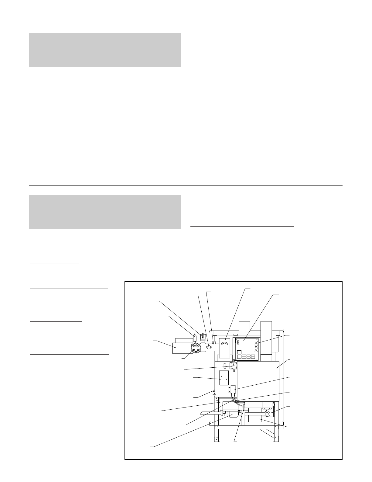
SECONDARY
RELIEF
VALVE
AUTOMATIC
AIR VENT
CIRC.
PUMP
WATER PRESSURE/
TEMPERATURE GAGE
24 V TRANSFORMER
ELECTRICAL JUNCTION
BOX
HOT SURFACE IGNITOR
AND FLAME SENSOR
BURNER
ENCLOSURE
PRESSURE SWITCH
LOW SIDE TUBING
GAS
VALVE
HIGH LIMIT
(OPTIONAL)
WATER
SUPPLY
MANIFOLD
WATER
HIGH
LIMIT
GAS VALVE
BIAS TUBING
ELECTRONIC
BOILER
CONTROL
DIAGNOSTIC
INDICATOR
LIGHTS
AIR FILTER BOX
PRESSURE
SWITCH
PRESSURE SWITCH
HIGH SIDE TUBING
AIR AND GAS
ORIFICE PLATE
COMBUSTION BLOWER
Page 3

At least once a year, check the air filter: Replace it
(recommended) or clean it. Remove the boiler front
cover to access the filter box. Turn latches 1/4 turn on
filter box cover to remove filter.
Slant/Fin replacement air filter, part number 66-0515,
must be used. The filter can be cleaned with soap and
water. Shake off excess moisture and after drying,
spray with an adhesive-type air filter spray. Make sure
filter box cover is secured tightly after replacing.
In the case of severe outside dust/dirt conditions which
cause above-average accumulation on the filter, it may
be necessary to change it (or clean it) more often. This
procedure may be done by user or service technician,
providing a record is kept of each replacement or
cleaning date to assure an established diligent routine.
ANNU
AL TECHNICIAN INSPECTIONS
Before each heating season, call your qualified
service technician to perform the following
inspections (and repair any problems encountered).
Check vent system: For corrosion, obstructions, leaks
or sagging. Will require disassembling and resealing of
vent tubing.
Check water system:
For water piping leaks, properly
filled boiler and proper system air elimination.
Check gas piping: For gas valve and piping leaks.
Check boiler controls: For correct settings and
functioning. To include safety controls and calibration.
Check air filter: Replace (recommended) or clean.
System heat exchanger and burner: For sooting,
corrosion or improper operation.
Combustion blower: It’s a sealed component which
does not require lubrication.
Circulator: Some models require lubrication. S.A.E. #20
oil recommended .
The Concept 21 control board, located behind the boiler
front cover, has a set of LED indicator lights which provide
important information at a glance about boiler operation:
Power Indicator (GREEN):
Steady ON means there is
electrical power to the boiler. Light will come on when
power is provided to boiler.
Diagnostic Indicator (RED):
Steady ON or intermittent
flashing indicates a system operation problem.
Flame Indicator (AMBER): Steady ON means the boiler is
running and proper flame detection is sensed.
WHA T THE INDICAT OR
LIGHTS TELLS Y OU
Before calling a qualified service technician, check the
following first:
• Room thermostat is calling for heat?
• Fuse or circuit breaker is OK?
• Boiler service switch is ON?
• Gas supply is available to gas meter?
• Manual main gas shutoff is open?
• Boiler gas valve knob is in ON position?
Then, observe indicator lights: You can help provide
useful information to the service technician so the
technician can arrive with appropriate replacement parts.
Carefully note the red diagnostic indicator light. (It can be
viewed by looking through the vents in the front cover.)
When a system failure occurs, and there’s power to the
boiler, the indicator light will show a series of quick
flashes. There will be a short interval between the series
when the indicator stops flashing.
Count the number of flashes that occur after the short
no-flashing interval. Using the chart above, determine
correct failure code for number of flashes you counted.
Call a qualilfied service technician and report your boiler
model plus the number of flashes you counted and the
code for the flashes.
Note: The boiler will attempt restart each hour and after a
power interruption. If boiler restarts, diagnostic light will
turn OFF. If boiler does not restart, diagnostic light will
return to either steady-on or the series of flashes.
IN CASE YOUR
BOILER SHUTS DOWN
BOILER FAILURE CODES
Indicator Fault Indicated
Steady on Control internal failure
1 Flash High limit open
2 Flashes No ignition
3 Flashes Pressure switch problem
4 Flashes Ignitor failure
5 Flashes Flame signal loss
6 Flashes Improper flame signal
CONCEPT 21
3
Page 4

SLANT/FIN CORPORATION, Greenvale, N.Y. 11548 • Phone: (516) 484-2600
FAX: (516) 484-5921 •
Canada: Slant/Fin
LTD/LTEE
, Mississauga, Ontario
www.slantfin.com
©Slant/Fin Corp. 1996.
LIGHTING INSTRUCTIONS (Reference For Labels 65-0640 and 65-0645)
CONCEPT 21
4
FOR YOUR SAFETY READ BEFORE OPERATING
WARNING: If you do not follow these instructions
exactly, a fire or explosion may result causing property
damage, personal injury or loss of life.
A. This appliance does not have a pilot. It is equipped with an
ignition device that automatically lights the burner. DO NOT
try to light the burner by hand.
B. BEFORE OPERATING smell all around the appliance area
for gas. Be sure to smell next to the floor because some gas
is heavier than air and will settle on the floor.
WHATTO DO IF YOU SMELL GAS
• DO NOT try to light any appliance.
• DO NOT touch any electric switch; DO NOT use any phone in
your building.
• Immediately call your gas supplier from a neighbor's phone.
Follow the gas supplier's instructions.
• If you cannot reach your gas supplier, call the fire department.
C. Use only your hand to turn the gas control knob or depress
and move the gas control selector arm. NEVER use tools. If
the knob will not turn or selector arm will not depress or
move by hand, DON'T try to repair it, call a qualified service
technician. Force or attempted repair may result in a fire or
explosion.
D. DO NOT use this appliance if any part has been underwater.
Immediately call a qualified service technician to inspect the
appliance and to replace any part of the control system and
any gas control which has been underwater.
OPERA
TING INSTRUCTIONS (Label 65-0640)
• STOP! Read the safety information above on this label.
• Set the room thermostat to lowest setting.
• Turn off all electric power to the appliance.
• This appliance is equipped with an ignition device which
automatically lights the burner. DO NOT try to light the
burner by hand.
• Remove control access panel.
• Turn gas control knob clockwise to “OFF” position.
• Wait five (5) minutes to clear out any gas. Then smell for
gas, including near the floor. If you smell gas, STOP! Follow
"B" in the safety information above on this label. If you don't
smell gas, go to the next step.
• Turn gas control knob counterclockwise to “ON”
position.
• Replace control access panel.
• Turn on all electric power to the appliance.
• Set room thermostat to desired setting.
• If the appliance will not operate, follow the instructions “To
Turn Off Gas To Appliance” and call your service technician
or gas supplier.
T
O TURN OFF GAS TO APPLIANCE
• Set room thermostat to lowest setting.
• Turn off all electric power to the appliance if service is to be
performed.
• Remove control access panel.
• Turn gas control knob clockwise to “OFF” position.
• Replace control access panel.
OPERA
TING INSTRUCTIONS (Label 65-0645)
• STOP! Read the safety information above on this label.
• Set the room thermostat to lowest setting.
• Turn off all electric power to the appliance.
• This appliance is equipped with an ignition device which
automatically lights the burner. DO NOT try to light the
burner by hand.
• Remove control access panel.
• Depress and move gas control selector arm left to
“OFF” position. Note: Arm cannot be turned to “OFF” unless
arm is pushed in slightly. DO NOT force.
• Wait five (5) minutes to clear out any gas. Then smell for
gas, including near the floor. If you smell gas, STOP! Follow
"B" in the safety information above on this label. If you don't
smell gas, go to the next step.
• Depress and move gas control selector arm right to
“ON” position.
• Replace control access panel.
• Turn on all electric power to the appliance.
• Set room thermostat to desired setting.
• If the appliance will not operate, follow the instructions “To
Turn Off Gas To Appliance” and call your service technician
or gas supplier.
T
O TURN OFF GAS TO APPLIANCE
• Set room thermostat to lowest setting.
• Turn off all electric power to the appliance if service is to be
performed.
• Remove control access panel.
• Depress and move gas control selector arm left to
“OFF” position.
• Replace control access panel.
Gas Control
Knob (shown
in "ON" position)
ON
OFF
Position
Indicator
®
 Loading...