

SLAGKRAFT SH125, SH170, SH150, SH150-TW, SH110-TW Instruction Manual
...
Artikelnummer 5017 743-R4
EuroTest
Certificate
Instruction manual
Horizontal Flail
Model:
SH125 / SH150 / SH170 / SH190 / SH210
SH110-TW / SH150-TW
Read through the entire instruction
manual before beginning operation.
English, User manual in original
Copyright All rights reserved, including the right to reproduce this manual, or parts thereof, in any form, without the
written permission of Cranab AB.

EuroTest
Certificate
Products sold after 1995-01-01 are to be CE-marked and in conformance with
the machine directive confirmed by EU.
The manufacturer (importer) holds responsibility for this in the EU and/or EES
area.
The EUROTEST mark indicates that the product has been inspected by a
testing station that is independent of the maker of the product, ie, third party
certification.
The EUROTEST mark shows that the product is independently inspected with
regard to common European requirements concerning safety and health related
to this product
To enable a testing station to issue certificates it must fulfil confirmed quality
requirements and its experts inspect the product on the basis of safety and
quality.
SMP Svensk Maskinprovning AB is approved to carry out this third party
certification.
SMP puts its ET-mark on the product when it considers that the product
conforms to EU’s machine directive.
2

C
ONTENTS
1 ............... ..................... ...................... ...................... ..................... ...................... ...................... ................. Introduction 5
Limitation of application.................................................................................. 5
Range of use.................................................................................................. 5
2 ............... ..................... ...................... ...................... ..................... ...................... ...................... ... General description 7
Identification................................................................................................... 7
Direction of rotation ........................................................................................ 8
3 ............... ..................... ...................... ...................... ..................... ...................... ...................... Technical description 9
Hydraulic fluids............................................................................................... 9
Filter ............................................................................................................... 9
Hub .............................................................................................................. 10
Safety cover ................................................................................................. 10
Hydraulic motor ............................................................................................ 10
Flail chain..................................................................................................... 10
Chain magazine and chain locks.................................................................. 11
Protective rubber mat................................................................................... 11
Chain curtain ................................................................................................ 11
Wear plates and back plate.......................................................................... 11
4 ............... ..................... ...................... ...................... ..................... ...................... ...................... ............ Technical data 12
Standard models .......................................................................................... 12
TW models................................................................................................... 13
5 ............... ..................... ...................... ...................... ..................... ...................... ...................... .................Safety rules 14
General safety rules ..................................................................................... 14
Safety instructions........................................................................................ 15
Warning decal .............................................................................................. 17
Lifting points................................................................................................. 19
Type plate .................................................................................................... 19
6 ............... ..................... ...................... ...................... ..................... ...................... ...................... .Connecting to carrier 20
Hoses........................................................................................................... 20
Connecting................................................................................................... 20
7 ............... ..................... ...................... ...................... ..................... ...................... ..................... Operating instructions 22
Before starting.............................................................................................. 22
Starting......................................................................................................... 22
Mode of operation ........................................................................................ 22
Hints for light clearing................................................................................... 23
Chain curtain ................................................................................................ 23
Flail chain, chain locks and chain magazine ................................................ 23
After operation, general instructions............................................................. 23
Long-term parking / storage..................................................................... 23
Check after long-term parking / storage................................................... 24
8 ............... ..................... ...................... ...................... ..................... ...................... ...................... ..................... ... Service 25
Electric welding ............................................................................................ 26
Maintenance schedule / Lubrication schedule ............................................. 27
Retightening of bolted joints - Table............................................................. 28
3

Lubrication schedule .................................................................................... 29
Lubricating the drive axle ............................................................................. 30
Cleaning the chain magazine ....................................................................... 30
Loading chain into the magazine.................................................................. 31
Changing the protective rubber mat ............................................................. 32
Changing the chain curtain .......................................................................... 32
Retightening bolted joints............................................................................. 33
Inspecting slot-and-wedge bolt joints ........................................................... 33
Inspecting bearings ...................................................................................... 34
Inspecting vibration damper under tilt mount ............................................... 34
9 ............... ..................... ...................... ...................... ..................... ...................... ...................... ........... EC Declaration 35
4

1 I
This instruction manual contains information that you should be conversant with
to operate and maintain the horizontal flail in the best way. Study the contents
carefully before putting the flail into operation and carefully follow the
instructions provided. This will ensure the best conditions for long useful life and
interference-free operation.
This instruction manual applies only to Slagkraft’s horizontal flail. Separate
instruction manuals are available for vertical flail, crane, bush clearing machine
type Compact and bush clearing machine with motor package.
Slagkraft reserves the right to freely alter the contents of instructions, directions
and specifications.
The spare parts catalogue is included as a supplement in this instruction
manual and it may contain several model variants than those dealt with in the
manual.
When ordering spare parts the serial number of the horizontal flail should be
stated (see type plate) in addition to the number of the spare part. The reason
for stating the serial number is that design changes may have been made that
could affect the choice of spare parts required.
NTRODUCTION
A machine card accompanies the horizontal flail on delivery indicating the type,
serial number and year of manufacture. If the horizontal flail is part of a
complete bush clearing machine there will also be a machine card for the whole
unit.
Limitation of application
Slagkraft’s flails can be mounted on other carriers than Slagkraft cranes.
Slagkraft’s tilting mounts are therefore available in a variety of designs. It is
essential that the base machine is inspected after fitting to ensure satisfactory
stability. To inspect stability, run the crane boom and horizontal flail to maximum
tilting moment, ie, maximum extended mode at right angles to the direction of
travel for the machine, just above ground level. If the base machine is unstable
it can be balanced with counterweights or stabilising cylinder. Consult Slagkraft
for approval of base machine / combination of flail model.
Range of use
The horizontal flail is designed solely for clearing thickets and bush vegetation
and must be used and maintained in accordance with directions in this
instruction manual. It is especially important that safety rules are adhered to.
5

Study the entire instruction manual before using the flail.
Before mounting it, study the section “connecting to carrier” and section
“Safety rules.”
If the horizontal flail is included in bush clearing machine Compact or
Motor package study also the instruction manual for Compact, Motor
package and Crane respectively.
6

2 G
ENERAL DESCRIPTION
Identification
The horizontal flail consists mainly of safety cover, hub and hydraulic motor and
chain magazine, chain curtain, protective rubber mat, and wear plates.
The type designation of the horizontal flail consists of a number of parts
describing the configuration of the flail. How this designation is built up and what
it means is shown below. The type designation is required in some cases to
enable ordering of the right spare part.
Type designation SH150-80-TW-90 means:
SH150 Working width 150cm
80 Indicates size of hydraulic motor in cc
TW Flail with two open sides, ie, two-way flail.
90 Turning of hub in relation to standard version. This turning is used
mainly on backhoes and excavators. Other turning may also occur.
Hub and hydraulic
motor, chain magazine
Back plate with rubber mat
Location of warning decal
Saftey cover
Protective rubber mat
Type plate
Wear plate
Chain curtain
7
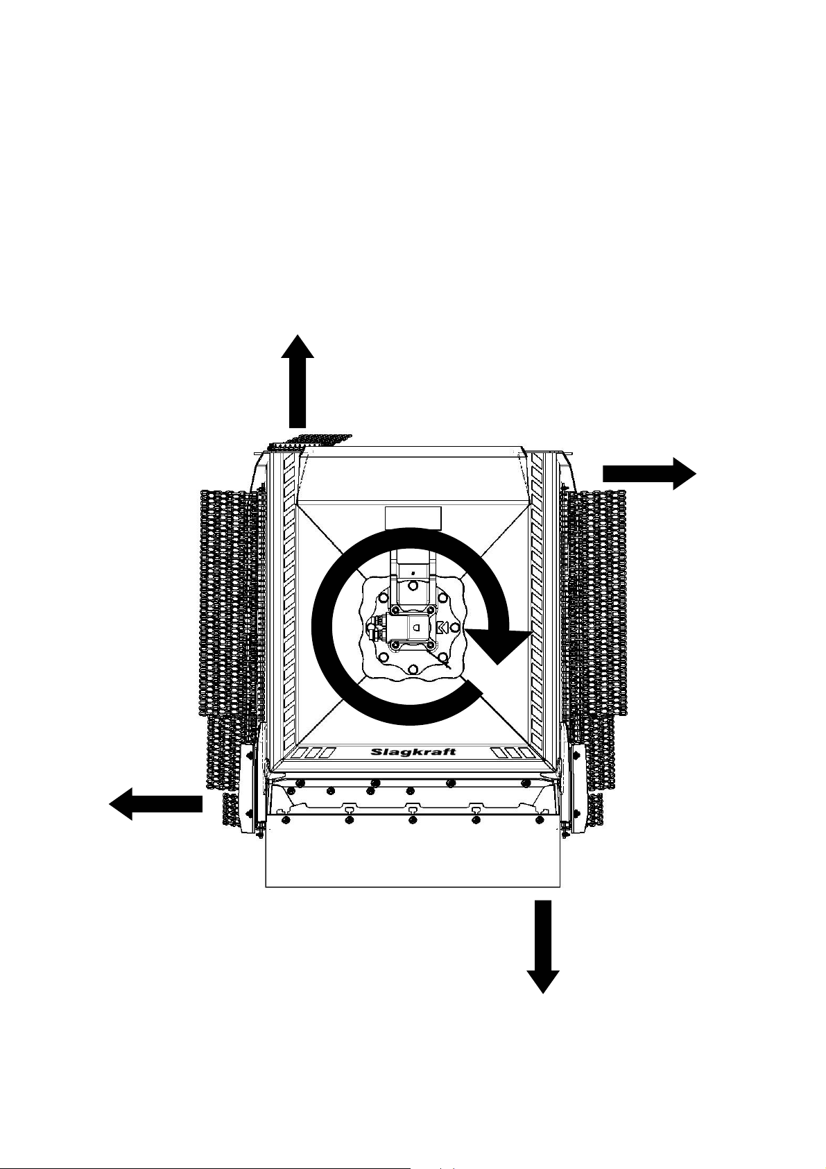
Direction of rotation
Flail have clockwise rotation seen from above. Wear plates, the hood and other
protections are designed for this rotation.
This rotation requires that the pressure line to the hydraulic motor is connected
to the hydraulic motor connection marked “A”.
8

3 T
The basic principle of the horizontal flail is two horizontally rotating chains.
Bushes and thickets are slashed and the vegetation is disintegrated into chips.
The horizontal flail can be operated using different chain diameters
recommended by Slagkraft, 10 or 13mm. Note that the chain magazine shall
only be filled with one dimension at a time. 10 and 13mm chain may never,
under any circumstances, be mixed in the same magazine.
For clearing with sweeping movement in terrain and for operation back and forth
a special flail is available with two open sides, ie, a two-way flail (type
designation TW). This flail is mainly used on excavators and other off road
machines. For use on roads a standard model is more suitable.
ECHNICAL DESCRIPTION
Hydraulic fluids
High requirements are put on the hydraulic fluid, which is the power-transmitting
component in a hydraulic system, to ensure the best possible efficiency and
useful life of the hydraulic system. The fluid, which is primarily intended for use
in equipment for outdoor use, must therefore be suitable for a wide temperature
range. The fluid shall contain additives to counteract foaming, improve film
strength and reduce viscosity temperature dependence.
Temperature range corresponding to the range for kinematic viscosity 150010mm2/s(=cSt) for the standardised hydraulic fluids SHS ISO VG 46.
We recommend fluid with characteristics in conformance with Swedish
Standard for hydraulic fluids SS 15 54 34. This standard includes conventional
hydraulic fluids that have a mineral oil base and also biologically decomposable
hydraulic fluids conforming to the standard and strict environment requirements.
Note. Some suppliers of pumps or components may have other
requirements regarding hydraulic fluids than those noted above. Ensure
therefore that the hydraulic fluid is approved prior to use.
Filter
For maximum useful life and performance the fluid must conform with regard to
cleanliness to ISO-norm 17/13 or better (ISO 4406). A 10µm (absolute) filter is
recommended. The hydraulic system must also be clean in general.
9

Hub
The hub consists of a housing with a spherical bearing in the lower part of the
housing. The lower part of the drive axle between the hydraulic motor and the
chain magazine is carried by the spherical bearing and at the upper end the
bearing is aligned by the outgoing axle of the hydraulic motor. A spline coupling
interconnects the drive axle and hydraulic motor.
Safety cover
The safety cover is made of hardened high-strength steel sheet. The wear
runners are replaceable. The protective rubber mat protects the front edge. The
TW type flail has two protective rubber mats. The cover also has a chain curtain
on the sides not fitted with a protective rubber mat. The chain curtain works as a
flexible extension of the cover and thus reduces the risk of flying stones.
Hydraulic motor
The hydraulic motor is of the bent-axis type with fixed displacement. The
outgoing axle is supported by bearings.
Flail chain
The flail chain is hardened and tempered in conformance with special
requirements for bush clearing. Flail chains are available in two sizes 10 and
13mm. Article number 1046 010 and 1046 002 respectively.
To facilitate identification of flail chain from Slagkraft it is painted blue and
identification marked according to Slagkraft’s instructions. When buying chain,
save the identification marking until the chain is used up.
Use only genuine flail chain to ensure that the guarantees and product
responsibility appertaining to the machine are not impeded
10
Chain magazine and chain locks
The chain magazine has a circular base plate. Two separate chain channels run
on the upper face of the base plate. Chain locks are fitted in the channel
openings to keep the chain in place. The chain magazine is made and heattreated to withstand hard wear. The flail chain is fed out manually.
Protective rubber mat
The protective rubber mat is fitted in the opening of the safety cover in the
direction of travel as protection against flying stones and other objects. The
protective rubber mat has several layers of cord.
Chain curtain
The chain curtain consists of chain links. This guard is fitted to the lower part of
the cover as a flexible extension of the cover.
Wear plates and back plate
The purpose of the wear plates is to protect the lower part of the safety cover
against wear. The wear plates are fastened by slot-and-wedge bolts. Wear
plates should be replaced at the latest when they are 6mm around the slot-andwedge bolts. If wear plates become unevenly worn they can suitably be moved
over to the opposite side to prolong their useful life. The back plate and the
safety cover are screwed into position and can be replaced as a single unit.
Replace the back plate when there is 2mm metal left at the thinnest position.
The responsibility of Slagkraft (CE and ET-markning) is not available if
there is used other flailchain, chainlock or chainmagazine or other not
genuine parts who direct affect the saftey.
11
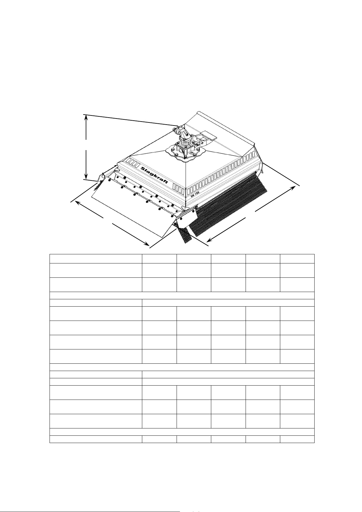
4 T
H
W
L
Standard models
ECHNICAL DATA
Model SH125 SH150 SH170 SH190 SH210
Working width (mm) 1250
49”
Hydraulic motor (cc) 60
3,66 cu.in
Outer dimensions (mm)
Length 1795
70”
Width 1550
61”
Height (above superstructure) 910
36”
Weight (kg) 525
1155 lbs
Hydraulic pressure
Rate of hydraulic flow
Min. (l/min) 100
Preferably (l/min) 120
Max. (l/min) 140
Power requirement (kW)
The unit can be delivered with different tilt mounts.
Due to continual product development we reserve the right to make changes.
Min. 210 bar (3045psi) / Max. 380 bar (5510psi)
26,4 gpm
31,7 gpm
37 gpm
40 (55hp) 45 (60hp) 70 (95hp) 75 (100hp) 80 (110hp)
1500
59”
80
4,88 cu.in
1970
77”
1760
69”
910
36”
595
1309 lbs
100
26,4 gpm
130
34,3 gpm
150
39,6 gpm
1700
67”
90
5,62 cu.in
2330
92”
2000
78”
910
36”
665
1463 lbs
100
26,4 gpm
130
34,3 gpm
160
39,6 gpm
1900
75”
110
6,71 cu.in
2560
100”
2200
86,5”
920
36”
750
1650 lbs
100
26,4 gpm
130
34,3 gpm
160
42,3 gpm
2100
82”
125
7,63 cu.in
2770
109”
2390
94”
970
37”
780
1716 lbs
120
31,7 gpm
145
38,3 gpm
170
45 gpm
12
 Loading...