

Page 1
ZERO EDGE PRO
INSTALLERS: PLEASE BE SURE TO LEAVE THIS
MANUAL WITH THE OWNER. THANK YOU!
Owner’s Manual
Page 2
ZERO EDGE PRO
3
Screen Innovations warrants its products, to the original purchaser only, to be
free from defects in materials and workmanship for a period of one (1) year from
the date of purchase by the original purchaser provided they are properly operated according to Screen Innovations’ instructions and are not damaged due to
improper handling or treatment after shipment from the factory.
This warranty does not apply to equipment showing evidence of misuse, abuse,
or accidental damage, or which has been tampered with or repaired by a person
other than authorized Screen Innovations personnel.
Screen Innovations’ sole obligation under this warranty shall be to repair or to
replace (at Screen Innovations’ option) the defective part of the merchandise.
Returns for service should be made to your Screen Innovations’ dealer. If it is
necessary for the dealer to return the screen or part to Screen Innovations,
transportation expenses to and from Screen Innovations are payable by the
purchaser and Screen Innovations is not responsible for damage in shipment. To
protect yourself against damage or loss in transit, insure the product and prepay
all transportation expenses.
THIS WARRANTY IS IN LIEU OF ALL OTHER WARRANTIES, EXPRESS OR IMPLIED, INCLUDING
WARRANTIES AS TO FITNESS FOR USE AND MERCHANT ABILITY. Any implied warranties of tness
for use, or merchantability, that may be mandated by statute or rule of law are limited to the one (1)
year warranty period. This warranty gives you specic legal rights, and you may also have other
rights, which vary from state-to-state. NO LIABILITY IS ASSUMED FOR EXPENSES OR DAMAGES
RESULTING FROM INTERRUPTION IN OPERATION OF EQUIPMENT, OR FOR INCIDENTAL, DIRECT, OR
CONSEQUENTIAL DAMAGES OF ANY NATURE.
In the event that there is a defect in materials or workmanship of a Screen Innovations product, you
may contact our Sales Partners at 9715-B Burnet Road Suite 400, Austin, TX 78758, (512) 832-6939.
IMPORTANT: THIS WARRANTY SHALL NOT BE VALID AND SCREEN INNOVATIONS SHALL NOT BE
BOUND BY THIS WARRANTY IF THE PRODUCT IS NOT OPERATED IN ACCORDANCE WITH SCREEN
INNOVATIONS’ WRITTEN INSTRUCTIONS.
Keep your sales receipt to prove the date of purchase and your original ownership.
LIMITED ONE YEAR WARRANTY
ON SCREEN INNOVATIONS PRODUCTS
APPLY S/N
STICKER HERE
?
512-832-6939
SCREENINNOVATIONS.COM
9715-B Burnet Road Suite 400, Austin,TX 78758
Page 3
ZERO EDGE PRO
54
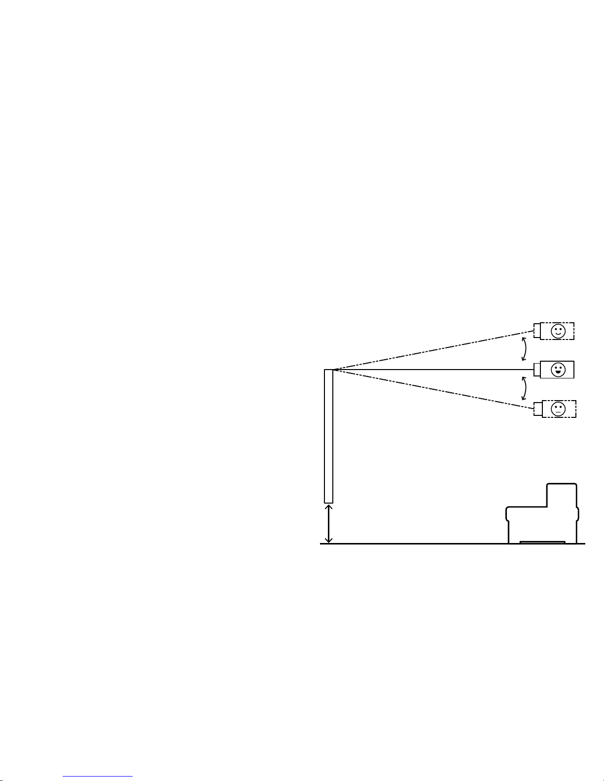
ZERO EDGE PRO SUGGESTED PROJECTOR PLACEMENT
11°
11°
SCREEN
Better
Best
Good
36”-42”
(91cm - 106cm)
Table of Contents
SUGGESTED PROJECTOR PLACEMENT . . . . . . . . . . . . . . . . . . . . . . . . . . . . . . . . . . . . . . . . . . . . . . . . . . . . . . . . . . . . . 5
STANDARD FRAME PARTS LIST . . . . . . . . . . . . . . . . . . . . . . . . . . . . . . . . . . . . . . . . . . . . . . . . . . . . . . . . . . . . . . . . . . . . 7
STANDARD FRAME ASSEMBLY . . . . . . . . . . . . . . . . . . . . . . . . . . . . . . . . . . . . . . . . . . . . . . . . . . . . . . . . . . . . . . . . . . . . . 9
SPLIT FRAME PARTS LIST . . . . . . . . . . . . . . . . . . . . . . . . . . . . . . . . . . . . . . . . . . . . . . . . . . . . . . . . . . . . . . . . . . . . . . . . 12
SPLIT FRAME ASSEMBLY . . . . . . . . . . . . . . . . . . . . . . . . . . . . . . . . . . . . . . . . . . . . . . . . . . . . . . . . . . . . . . . . . . . . . . . . . 14
LED LIGHTS ATTACHMENT . . . . . . . . . . . . . . . . . . . . . . . . . . . . . . . . . . . . . . . . . . . . . . . . . . . . . . . . . . . . . . . . . . . . . . . 18
BLACK DIAMOND OR SHORT THROW ATTACHMENT . . . . . . . . . . . . . . . . . . . . . . . . . . . . . . . . . . . . . . . . . . . . . . . . 21
SLATE OR PURE ATTACHMENT . . . . . . . . . . . . . . . . . . . . . . . . . . . . . . . . . . . . . . . . . . . . . . . . . . . . . . . . . . . . . . . . . . . 25
BLACK BACKER ATTACHMENT . . . . . . . . . . . . . . . . . . . . . . . . . . . . . . . . . . . . . . . . . . . . . . . . . . . . . . . . . . . . . . . . . . . . . . . . . . 28
MAESTRO ATTACHMENT . . . . . . . . . . . . . . . . . . . . . . . . . . . . . . . . . . . . . . . . . . . . . . . . . . . . . . . . . . . . . . . . . . . . . . . . . 29
BLACK BACKER ATTACHMENT . . . . . . . . . . . . . . . . . . . . . . . . . . . . . . . . . . . . . . . . . . . . . . . . . . . . . . . . . . . . . . . . . . . . . . . . . . 32
SMALL TRIM ATTACHMENT . . . . . . . . . . . . . . . . . . . . . . . . . . . . . . . . . . . . . . . . . . . . . . . . . . . . . . . . . . . . . . . . . . . . . . 34
MEDIUM OR LARGE TRIM ATTACHMENT . . . . . . . . . . . . . . . . . . . . . . . . . . . . . . . . . . . . . . . . . . . . . . . . . . . . . . . . . . . 36
LOGO ATTACHMENT . . . . . . . . . . . . . . . . . . . . . . . . . . . . . . . . . . . . . . . . . . . . . . . . . . . . . . . . . . . . . . . . . . . . . . . . . . . . . 38
TRIM REMOVAL . . . . . . . . . . . . . . . . . . . . . . . . . . . . . . . . . . . . . . . . . . . . . . . . . . . . . . . . . . . . . . . . . . . . . . . . . . . . . . . . . 39
WALL INSTALLATION . . . . . . . . . . . . . . . . . . . . . . . . . . . . . . . . . . . . . . . . . . . . . . . . . . . . . . . . . . . . . . . . . . . . . . . . . . . . 41
FLOWN INSTALLATION . . . . . . . . . . . . . . . . . . . . . . . . . . . . . . . . . . . . . . . . . . . . . . . . . . . . . . . . . . . . . . . . . . . . . . . . . . . 43
IR LIGHTING HEX CODES . . . . . . . . . . . . . . . . . . . . . . . . . . . . . . . . . . . . . . . . . . . . . . . . . . . . . . . . . . . . . . . . . . . . . . . . . 45
IP CONTROLLED LIGHTING SETUP . . . . . . . . . . . . . . . . . . . . . . . . . . . . . . . . . . . . . . . . . . . . . . . . . . . . . . . . . . . . . . . . 46
Page 4
7
STANDARD
6
ZERO EDGE PRO
SPLIT
STANDARD
7
12
PRE ASSEMBLED
39
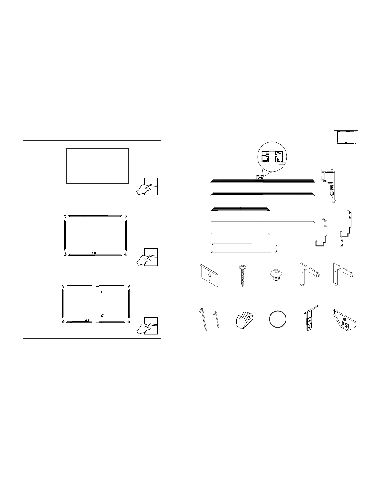
STANDARD FRAME PARTS LIST
2X
1X
Hardware Kit
1X
1X
2X
2X
(LED Lights Only)
Wall Brackets Mounting
Screws
4X
1/4-20 x 1/4’’
Screws
(Small trim only)
4X Thin Corner
Brackets
4X Thick Corner
Brackets
1/8’’ & 5/32’’
Hex Keys
Bungees
(Maestro only)
SI Attachment Bands
(Black Diamond and Short
Throw Only)
4X Gloves
1/2’’ Small trim
option
1 1/2’’ or 2’’
trim option
Acrylic Logo
Page 5
98
STANDARD STANDARD
Flying Mount Only
2X Flown Ceiling
Mount
2X Flown
Cable
LED Remote
LED IR Controlled Only
2X Flown Screen
Mount
If IP controlled LED lights are ordered, Phillips Hue hub must be purchased
and set up separately. See page 46 for IP lighting Instructions.
1
2
Thin Bracket
Thick Bracket
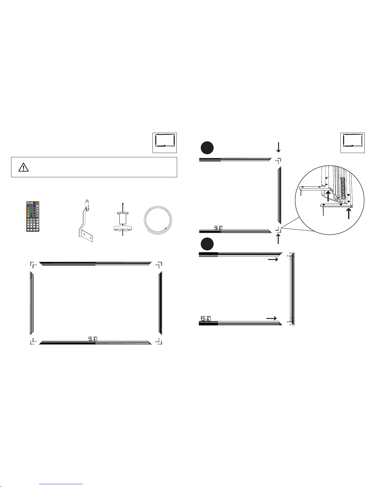
Insert the thin corner brackets into the outside channels and the thick corner brackets
into the inside channels of the vertical frames. Then slide into the channels in the
horizontal frames.
STANDARD FRAME ASSEMBLY
Page 6
1110
STANDARD STANDARD
4
3
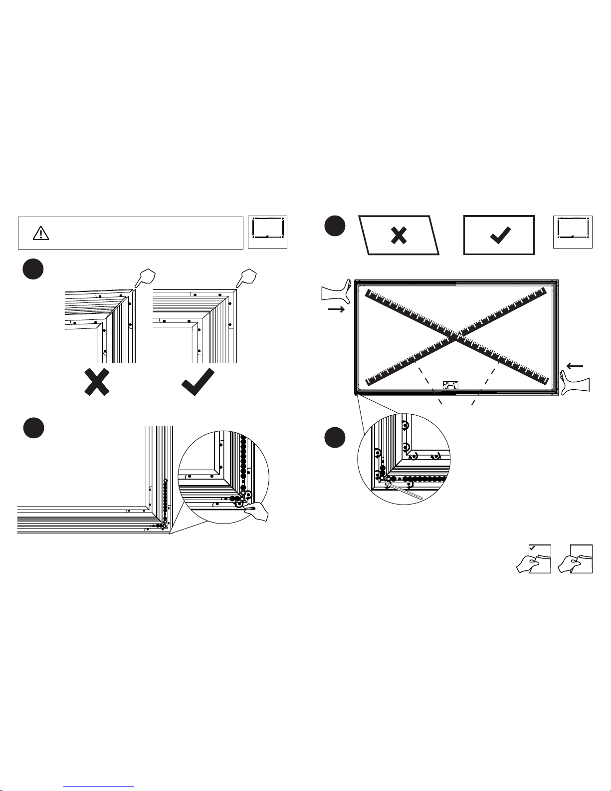
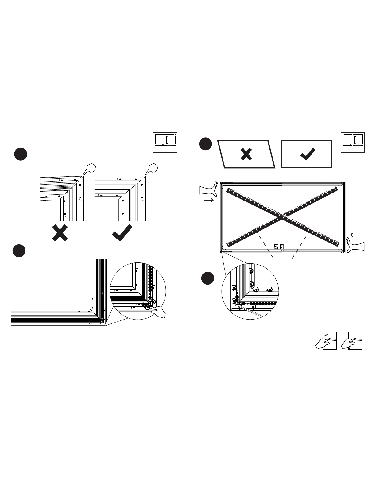
Make sure the points on the frame pieces line up. Then nger tighten 2 of the set screws
to lock in the corners.
6
5
A = B
A B
18 20
LED
Measure the diagonals to check if frame is square. If one diagonal is longer then push
on the corners at that diagonal. Tighten all set screws once the diagonals are equal to
within 1/8’’.
NOTE: If using AT or Maestro material then check to make
sure the channel nuts are installed in the inner channel
before proceeding.
Page 7
1312
SPLITSPLIT
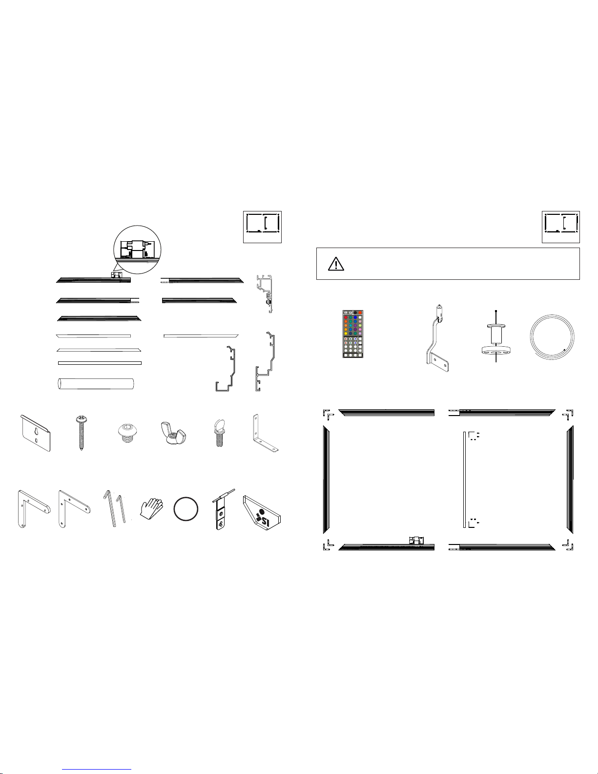
SPLIT FRAME PARTS LIST
1X
1X
1X
1X
2X
2X
2X
2X
1X
Hardware Kit
1X
(LED Lights Only)
Wall Brackets Mounting
Screws
12X
1/4-20 x 1/4’’
Screws
(Small Trim Only)
4X Thin Corner
Brackets
4X Thick Corner
Brackets
4X Gloves
4X
1/4-20 Wing nuts
4X
1/4-20 Thumb
Screws
2X Vertical
Support
Brackets
1/8’’ & 5/32’’ or
3/32’’ Hex Keys
1/2’’ Small trim
option
1 1/2’’ or 2’’
Trim option
Acrylic Logo
Flying Mount Only
2X Flown Ceiling
Mount
2X Flown
Cable
LED Remote
LED IR Controlled Only
2X Flown Screen
Mount
If IP controlled LED lights are ordered, Phillips Hue hub must be purchased
and set up separately, see page 46 for IP lighting Instructions.
Bungees
(Maestro only)
SI Attachment
Bands
(Black Diamond and
Short Throw Only)
Page 8
1514
SPLITSPLIT
1
2
Thin Bracket
Thick Bracket
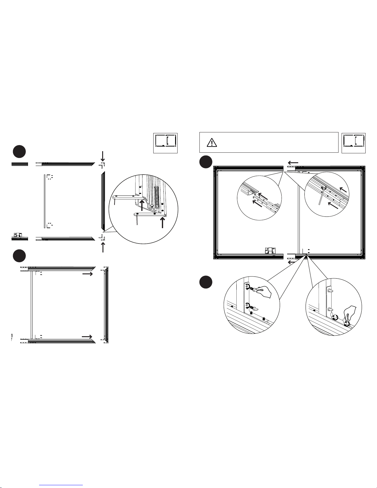
Insert the thin corner brackets
into the outside channels and
the thick corner brackets into the
inside channels of the vertical
frames. Then slide into the
channels in the horizontal frames.
SPLIT FRAME ASSEMBLY
3
4
Slide the horizontal frame pieces together and secure with the splice bars. Then attach
the vertical support to the frame as shown.
NOTE: If using AT or Maestro material then check to make
sure the channel nuts are installed in the inner channel
before proceeding.
Page 9
1716
SPLITSPLIT
7
8
A = B
A B
18 20
LED
Measure the diagonals to check if frame
is square. If one diagonal is longer then
push on the corners at that diagonal.
Tighten all set screws once the diagonals
are equal to within 1/8’’.
5
6
Make sure the points on the frame pieces line up. Then nger tighten 2 of the set screws
to lock in the corners.
Page 10
ZERO EDGE PRO
1918
ZERO EDGE PROLED LIGHTS ATTACHMENT
1
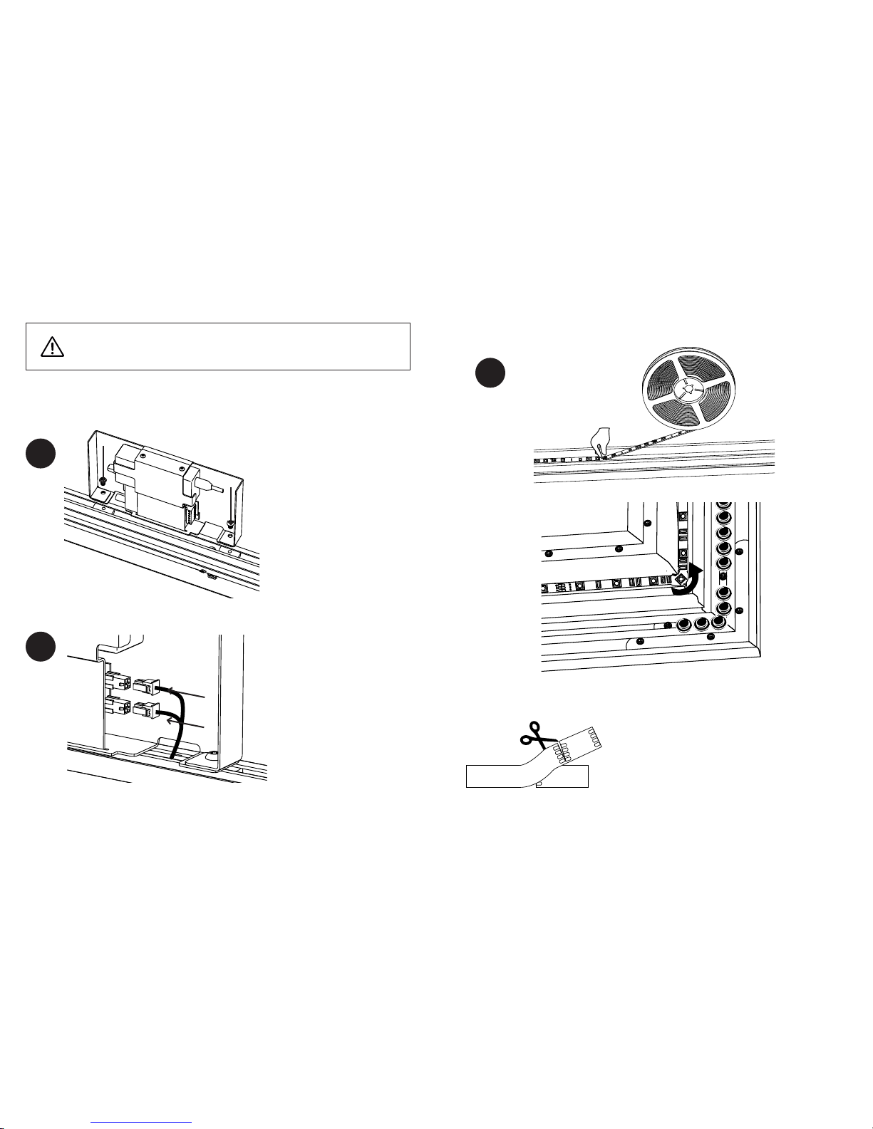
Connect the lighting harness
with the included screws to
the nuts in the frame piece
with the lights attached to it.
NOTE: Steps 1 and 2 will have already been completed if possible to be shipped that way.
If so skip to step 3.
Plug in the lights to the
controller plugs.
2
If IP controlled LED lights are ordered, Phillips Hue hub must be purchased
and set up separately, see page 50 for IP lighting Instructions.
3
Cut the light strips at the copper pad as indicated to
the correct length such that they just overlap at the
middle of the top frame piece. DO NOT cut the light
strips at any other location.
+12V
B
G
R
+12V
B
G
R
CUT HERE
Press in the lights to the channel on the frame. Do not crease the lights at the corners.
Page 11
BD or ST
2120
ZERO EDGE PRO
Material?
BLACK DIAMOND or
SHORT THROW
21
MAESTRO
29
SLATE or PURE
25
1
BLACK DIAMOND OR SHORT THROW ATTACHMENT
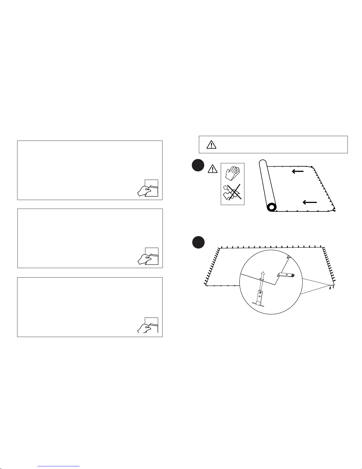
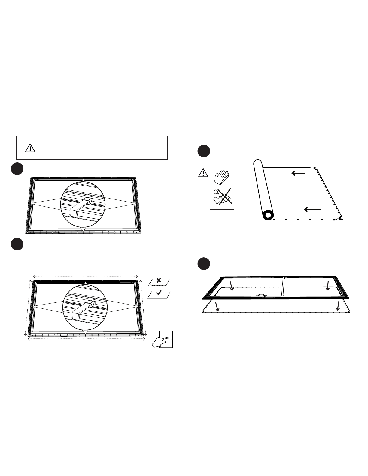
Wear gloves when handling material. Carefully unroll the screen material out onto a
clean floor. Take care to not bend or crease the screen material.
2
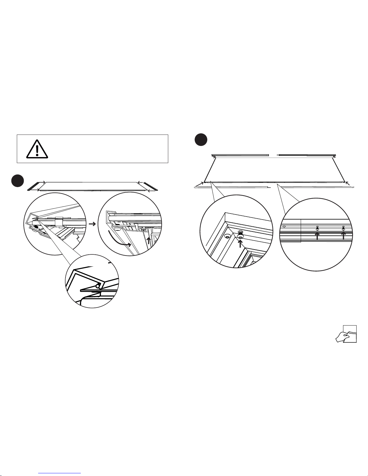
Insert the BD attaching bands up through the slots in the material. Note the orientation
of the bands such that the bent band will naturally lie away from the material and the UP
label is visible.
Black diamond and short throw material are highly sensitive. Take
care to not bend or crease the material as you unroll it.
Page 12
BD or STBD or ST
2322
3
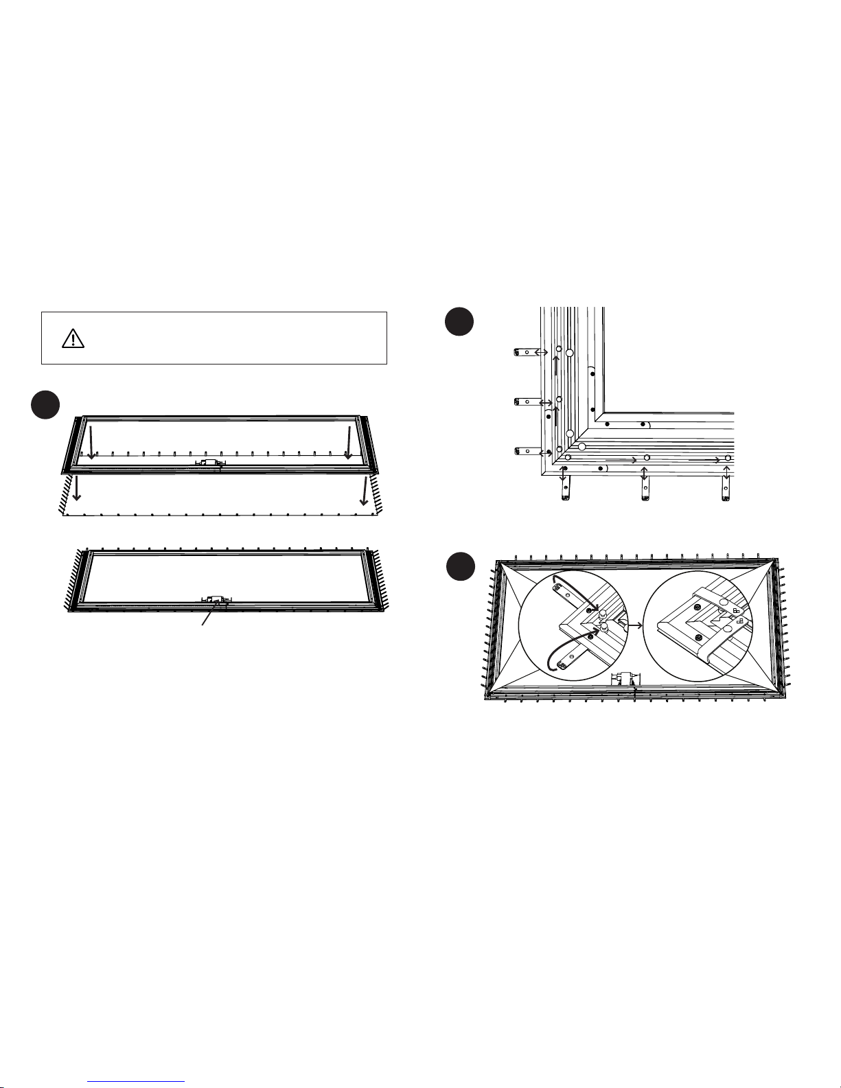
Carefully lie the frame onto the screen material making sure to not dent the screen
material with the frame or frame corners. Align the edges of the screen material with
the edges of the frame.
NOTE: For short throw material make sure the material is oriented such that the LED
harness is at the bottom of the screen material.
DO NOT drop the frame onto the screen material. Frame must
be gently set down onto the screen material to avoid denting the
material.
For Short Throw
LED harness at bottom
4
5
Remove and discard the black retaining bumpers then spread out the posts so that they
align with the attaching bands.
Pull up and then over on the bands to attach to the posts so that the SI diamonds are
showing. Do this at all 4 corners before proceeding. Make sure the screen material is
centered about the frame by making sure the edges of the screen material line up with
the edges of the frame.
Page 13
SLATE or PURE
25
BD or ST
24
6
7
33
As you continue to attach the bands make sure the material is
centered about the frame. This is easy to tell by making sure the
edge of the material is flush with the edge of the frame.
1
2
SLATE OR PURE ATTACHMENT
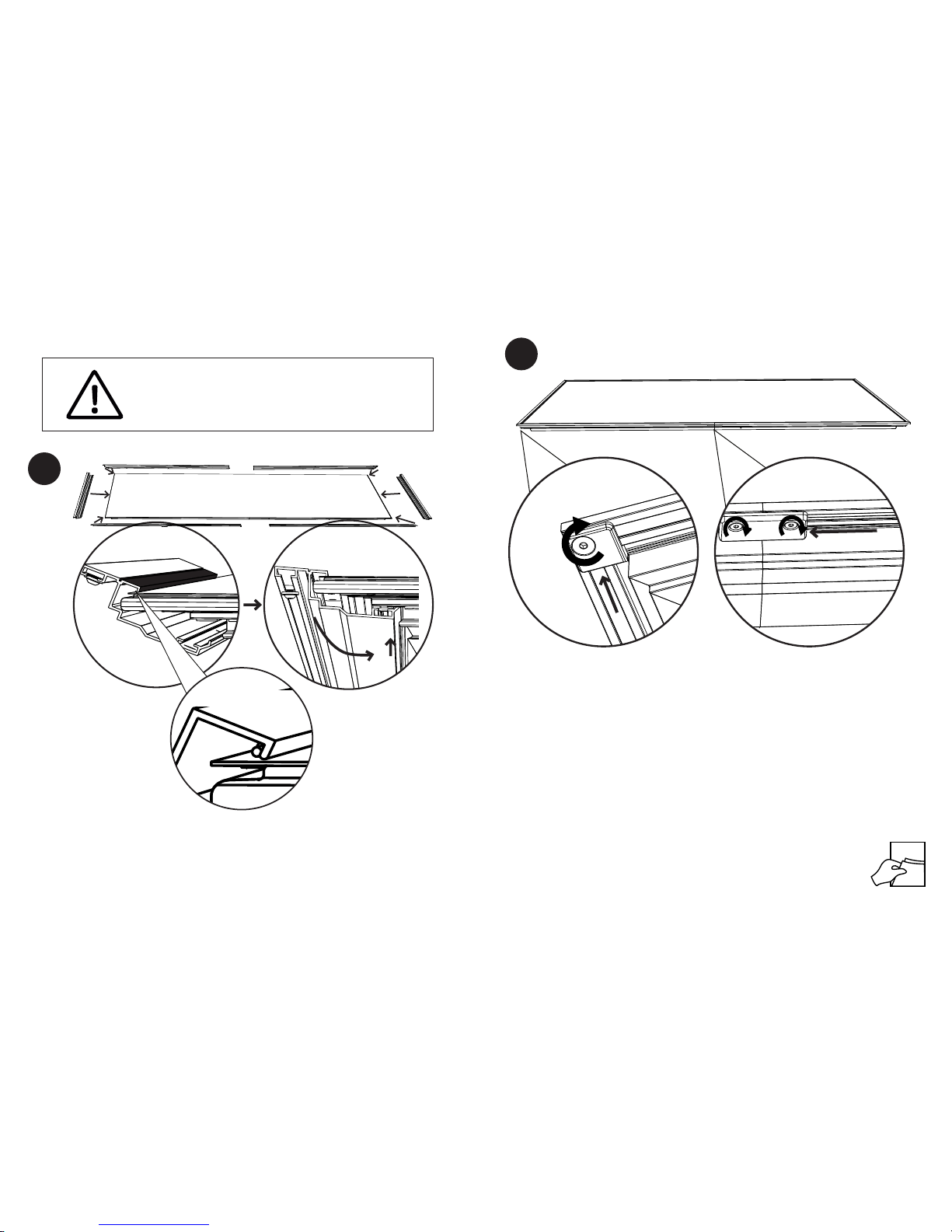
Wear gloves when handling material. Carefully unroll the screen material out onto a
clean floor. Take care to not bend or crease the screen material.
Carefully lie the frame onto the screen material. Center the frame about the screen
material.
2
2
1 1
alternate sides
when attaching
Attach one band in the middle of all four frame pieces. This will center the
material.
Attach the bands on the vertical frame pieces from the center towards the
ends. Alternate sides to keep tension even on both sides. Make sure the edges
of the material are even with the edges of the frame. Then, attach the bands on
the horizontal frame pieces from the center towards the ends. Alternate sides
to keep the tension even on both sides.
Page 14
SLATE or PURESLATE or PURE
2726
3
4
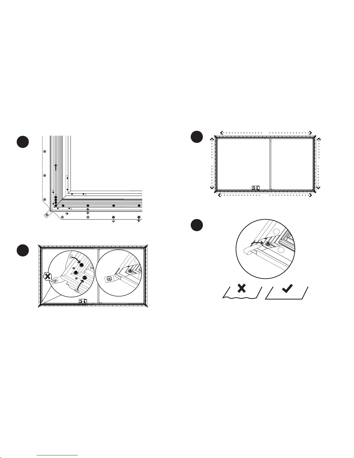
Remove and discard the black retaining bumpers then spread out the posts so that they
aligning with the snaps on the screen material.
At all 4 corners attach the snaps at the end of screen material but NOT the snap on
the corner tab. Make sure the screen material is centered about the frame before
proceeding.
5
6
Attach the snaps at the middle and then work your way towards the ends on all 4 sides
of the screen material.
Finally attach the snaps at the corner tabs. Then check to make sure the screen material
is flat and adjust the snap positions if necessary to flatten the screen material. Once all
snaps are attached ip screen over and make sure that the screen material is at and
tight everywhere.
Page 15
MAESTRO
29
SLATE or PURE
28
33
7
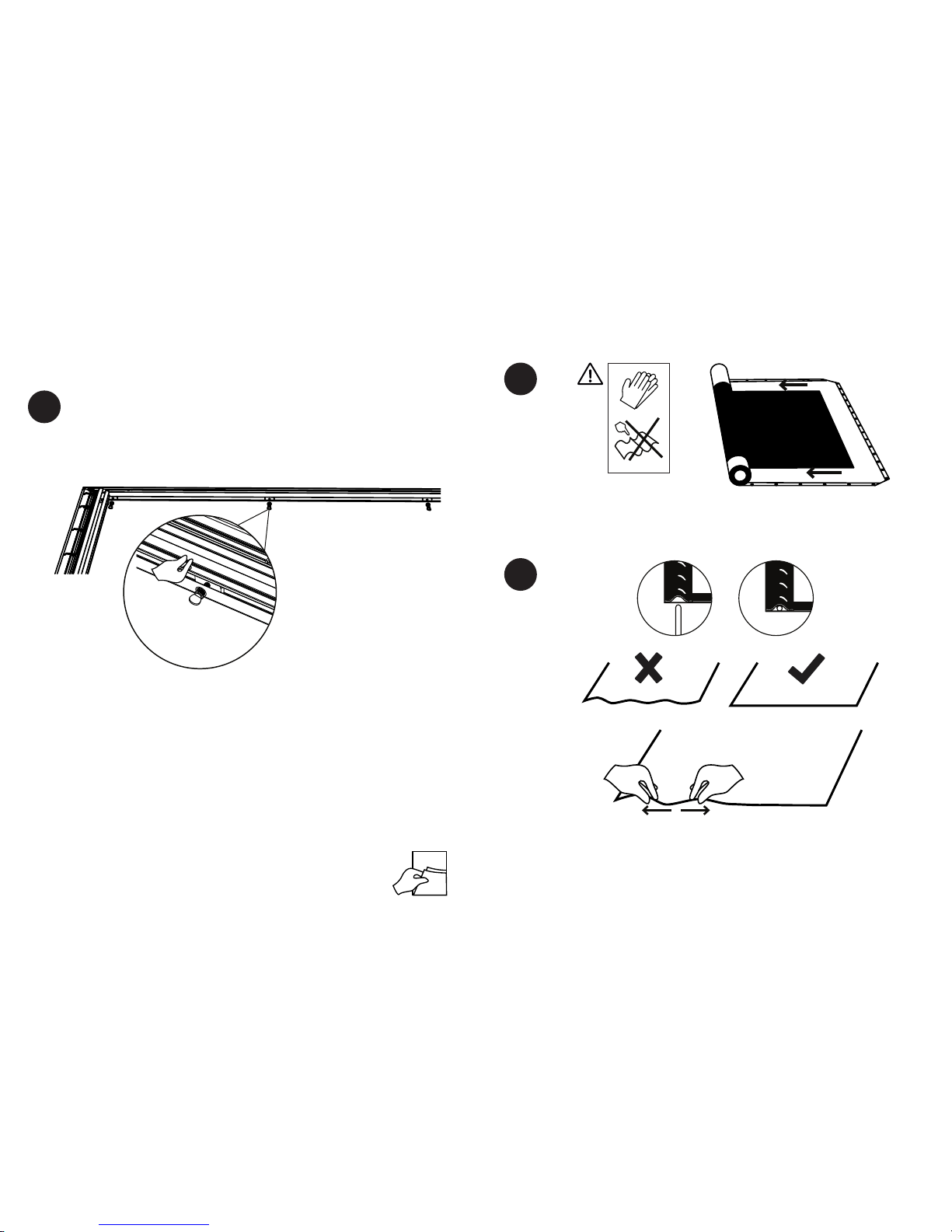
For AT Material Only
Spread out the nuts in the top frame piece and attach the black backer to the nuts with
the thumb screws. Flip screen over and make sure that the screen material is at and
tight everywhere.
Note: If the notch in the black backer is not aligned with the vertical support then flip it
over.
Acoustically Transparent (AT) materials come with a black backer that must
be installed to eliminate shine through.
1
2
MAESTRO ATTACHMENT
Insert the rods into the pocket in the screen material. Make sure the screen material is
lying flat. If the screen material is bunched up at the rods then work from the middle out
spreading out the screen material until it is flat.
Wear gloves when handling material. Carefully unroll the screen material out onto a
clean floor. Take care to not bend or crease the screen material.
BLACK BACKER ATTACHMENT
Page 16
MAESTROMAESTRO
3130
3
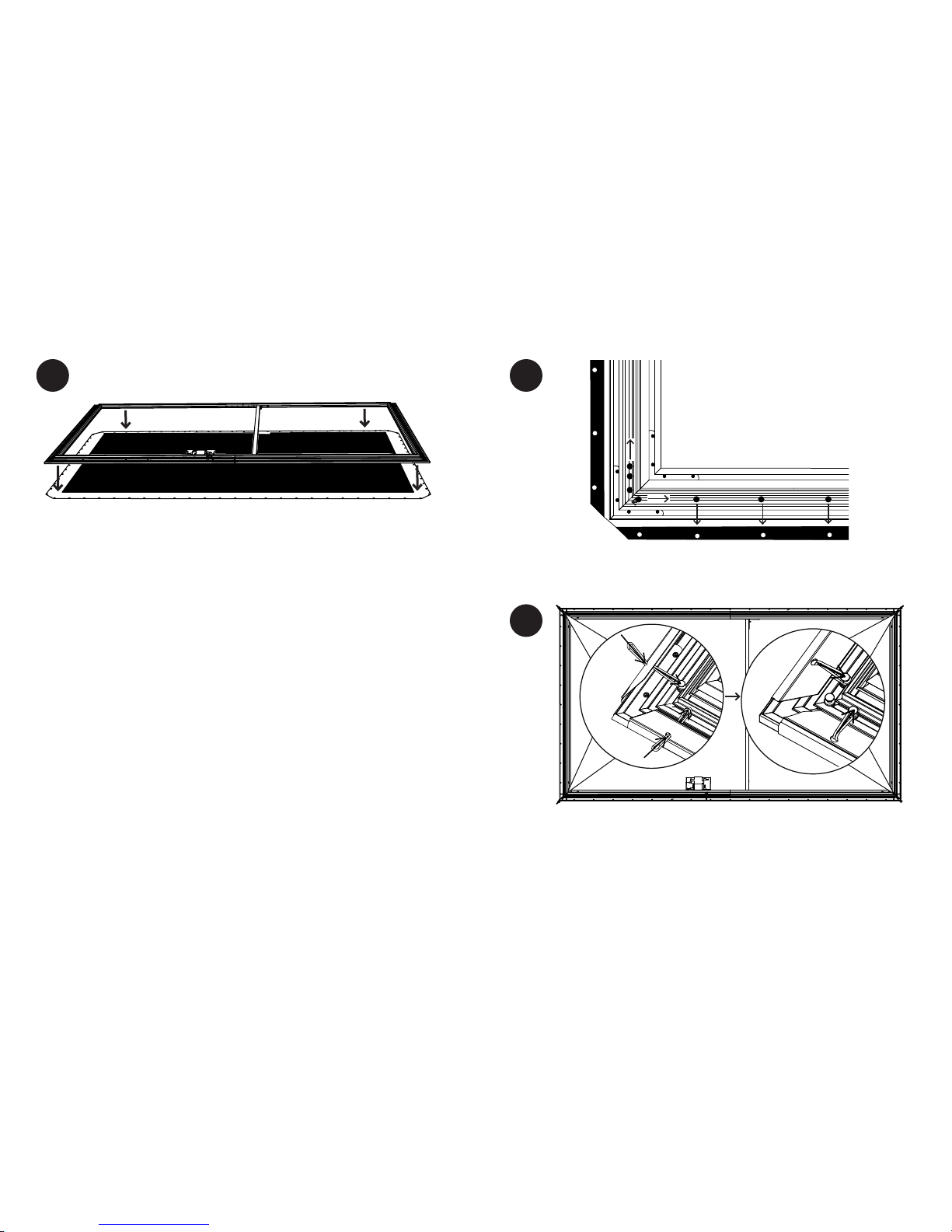
Carefully lay the frame onto the screen material. Center the frame about the screen
material.
4
5
Remove and discard the black retaining bumpers then spread out the posts so that they
aligning with the holes in the screen material.
Put one end of the bungee through the hole in the material and place over the post
while holding the other end. Then pull the other end of the over the post. Do this at all
4 corners rst. Make sure the screen material is centered about the frame before
proceeding.
Page 17
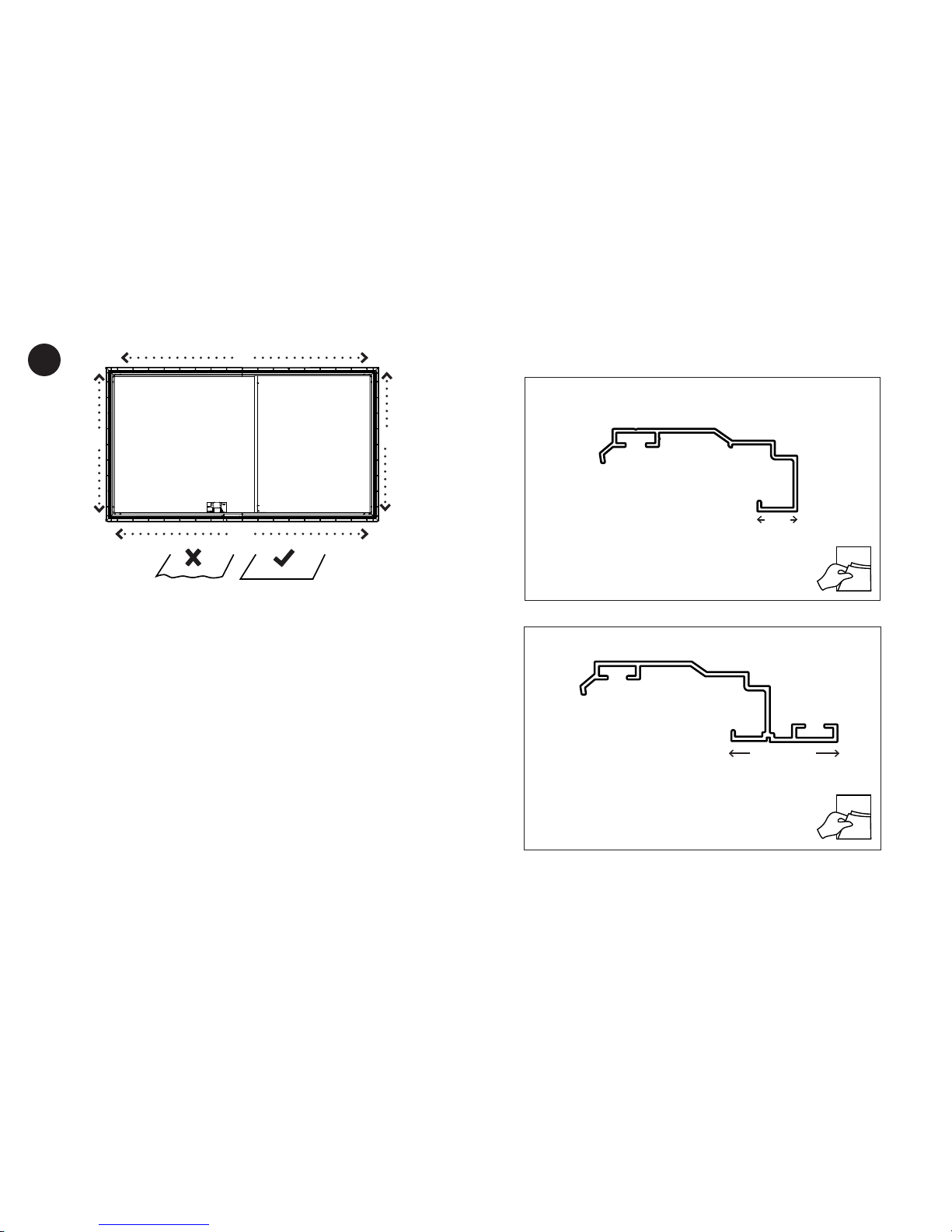
ZERO EDGE PRO
33
MAESTRO
32
6
Attach the bungees at the middle and then work your way towards the ends on all 4
sides of the screen material. Check to make sure the screen material is flat and adjust
the bungee positions if necessary to flatten the screen material.
MEDIUM OR LARGE TRIM
SMALL TRIM
34
36
1/2’’
1 1/2’’ OR 2’’
Page 18
SMALL TRIMSMALL TRIM
3534
1
SMALL TRIM ATTACHMENT
Black Diamond only
Attach the vertical trim rst onto the screen as shown above.
NOTE: For Black Diamond and Short Throw make sure that the front lip of the trim is
over the attaching bands before rotating the trim into place.
2
Attach the horizontal trim pieces. Align and secure the corners with the 1/4-20 x 1/4’’
screws as shown. Hold the trim corners together while tightening the screw to ensure a
well aligned corner.
Split Frame Only: Connect the horizontals at the middle by installing quantity 4 1/4-20 x
1/4’’ screws trough the trim into the splice bar.
Split Frame Only
38
Velvet on trim is delicate, handle with care.
Install trim with screen at on oor, NOT
when screen is vertical.
Page 19
MEDIUM or LARGE TRIMMEDIUM or LARGE TRIM
3736
1
MEDIUM OR LARGE TRIM ATTACHMENT
Attach the trim onto the screen as seen above.
NOTE: For Black Diamond make sure that the front lip of the trim is over the attaching
bands before rotating the trim into place.
Black Diamond only
2
Loosen the screw on the corner plate, slide over to the corner, and hold the corners
together while tightening the screw to secure the well aligned corners.
Split Frame Only: Loosen the screw on the center cover plate, slide over to the middle,
and hold together trim pieces while tightening the screw to secure the well aligned
center trim seam.
Split Frame Only
38
Velvet on trim is delicate, handle with care.
Install trim with screen at on oor, NOT
when screen is vertical.
Page 20
ZERO EDGE PRO
3938
ZERO EDGE PRO
1
LOGO ATTACHMENT
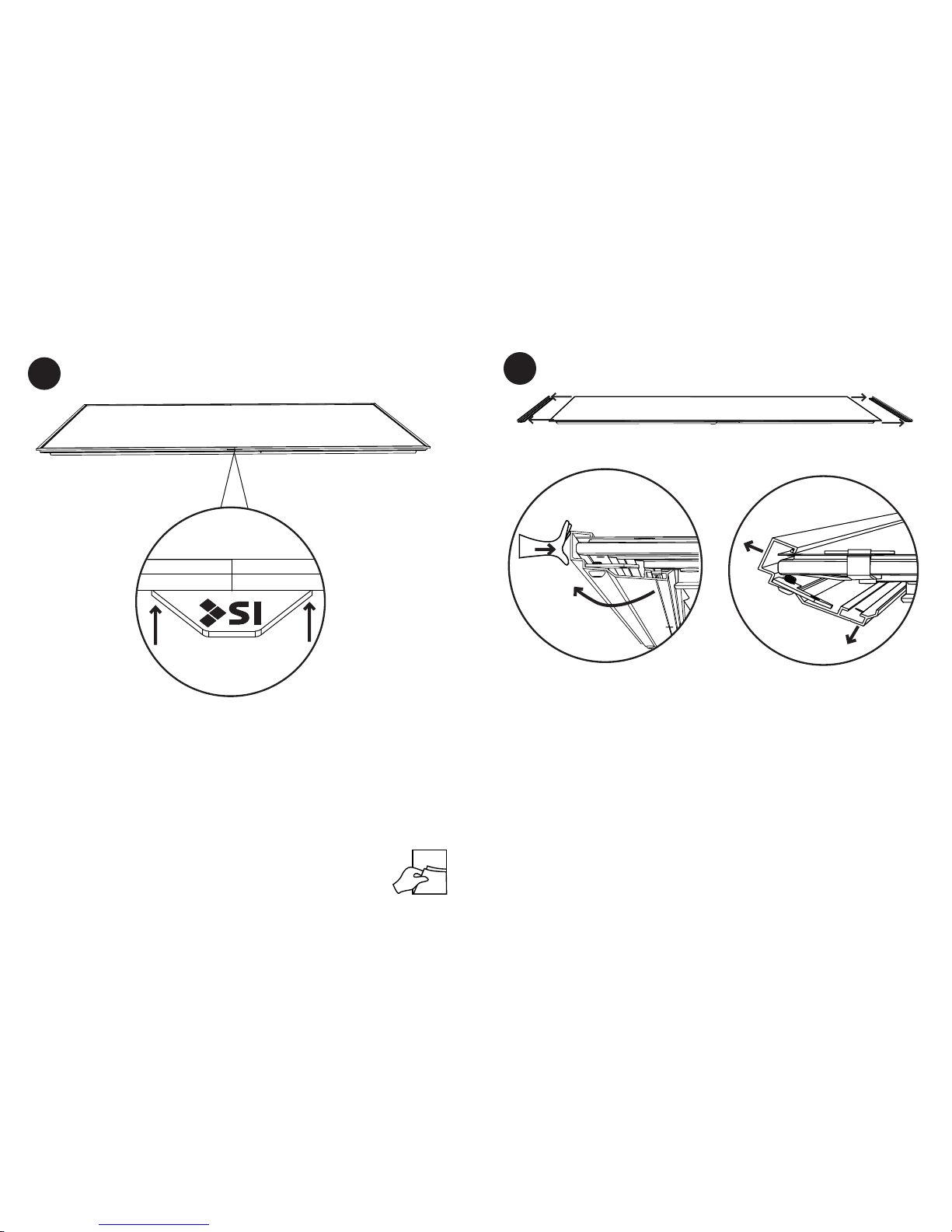
Attach the logo to the trim by holding it at the middle of the horizontal trim and letting
the magnet pull it to and attach to the back of the trim.
NOTE: You can also attach the logo to the screen after it is installed on the wall or flown.
The trim can attach to either horizontal trim piece. However if your screen has lights
make sure the trim is attached to the side of the screen with the lighting harness.
TRIM REMOVAL
Disconnect the trim at the corners by either removing the screw or loosening the corner
plate and sliding over.
Then push in on trim pieces while rotating trim off of frame. The magnet will hold the
trim in place at rst. Therfore you may need to shake the trim at rst to get it to rotate
away from the frame.
1
40
Page 21
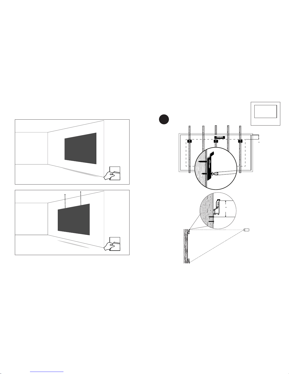
41
WALL MOUNT
40
ZERO EDGE PRO
WALL MOUNT
FLYING MOUNT
41
43
1
TOP OF VIEWING
4
3
4
"
(12.1 cm)
LEVEL
Structural Support
Structural Support
3
3
4
"
(9.5 cm)
TOP OF VIEWING
WALL INSTALLATION
Page 22
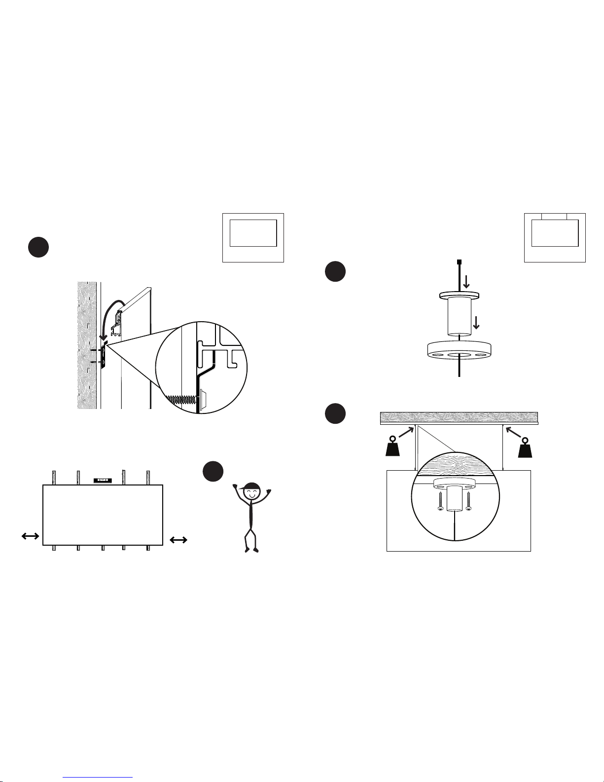
43
FLYING MOUNT
42
WALL MOUNT
3
2
1
2
100 lbs
(45.3 kg)
100 lbs
(45.3 kg)
FLOWN INSTALLATION
Page 23
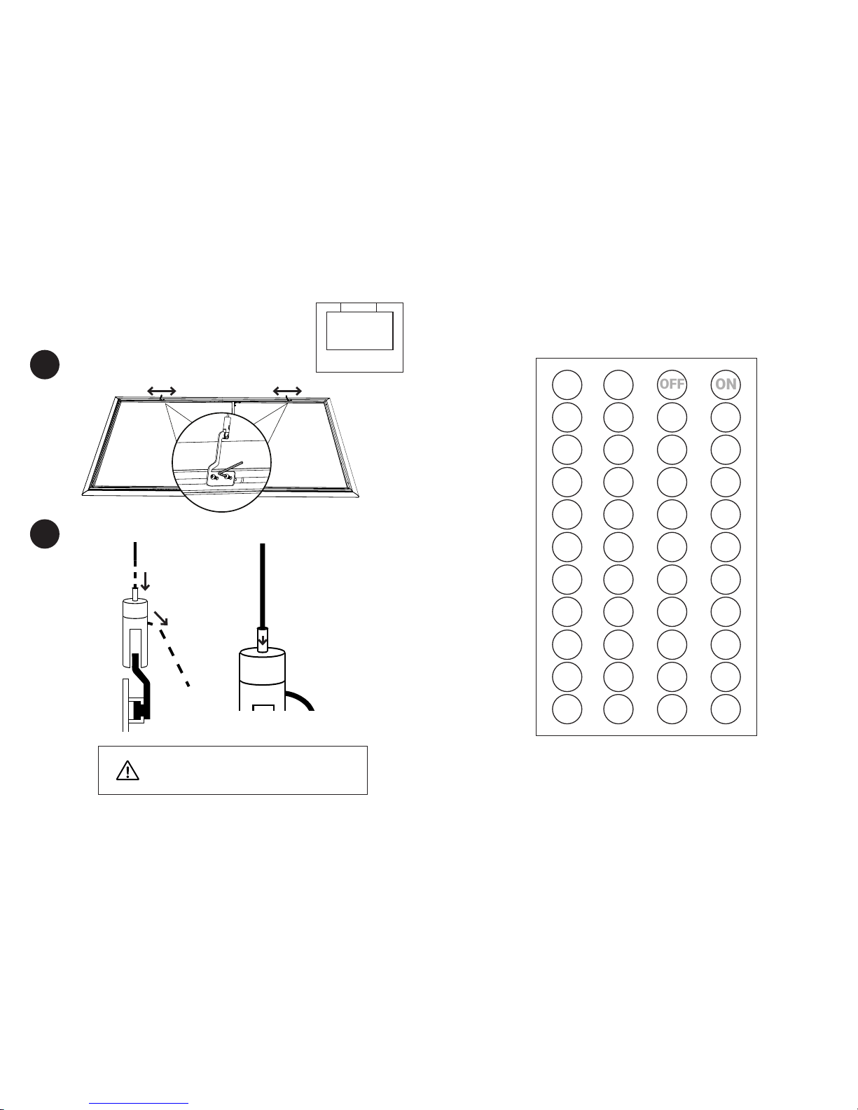
ZERO EDGE PRO
4544
FLYING MOUNT
3
We recommend you don’t cut the extra cables for
future adjustability. Simply tape the extra cable to the
back of the screen frame.
NOTE: If you pull too far
the screen can be
lowered by pushing down
the button on the top of
the flying mount.
4
IR Controlled Option Only
20 13
5C A3
20 13
5D A2
20 13
41 BE
20 13
40 BF
20 13
58 A7
20 13
59 A6
20 13
45 BA
20 13
44 BB
20 13
54 AB
20 13
55 AA
20 13
49 B6
20 13
48 B7
20 13
50 AF
20 13
51 AE
20 13
4D B2
20 13
4C B3
20 13
1C E3
20 13
1D E2
20 13
1E E1
20 13
1F E0
20 13
18 E7
20 13
19 E6
20 13
1A E5
20 13
1B E4
20 13
14 EB
20 13
15 EA
20 13
16 E9
20 13
17 E8
20 13
10 EF
20 13
11 EE
20 13
12 ED
20 13
13 EC
20 13
0C F3
20 13
0D F2
20 13
0E F1
20 13
0F F0
20 13
08 F7
20 13
09 F6
20 13
0A F5
20 13
0B F4
20 13
04 FB
20 13
05 FA
20 13
06 F9
20 13
07 F8
OFF
ON
IR LIGHTING HEX CODES
Page 24

46
ZERO EDGE PRO
Screen Innovations LED IP Setup Instructions
Reset Instructions (Required to connect to a different Phillips Hue)
Before attempting to connect your LED IP to Phillips Hue, ensure that the Hue Bridge is powered on and connected to
the local WIFI network.
Note: The LED IP can be connected and controlled by only one Phillips Hue Bridge at a time
1. Begin by connecting the power supply to an electrical outlet. After a few seconds, the LEDs should power on to a
white color.
2. Open the Phillips Hue app on your smart device, and navigate to Light Setup in the settings tab.
3. Press the Plus button in the lower right-hand corner, then press Search.
4. It can take several seconds to connect. Once connected, the LEDs will light green.
5. The LED IP will appear in the Phillips Hue app as Extended C olor light 1 and Dimmable light 1. Only use
Extended
Color Light 1 to control the LED’s. Dimmable Light 1 should be deleted.
6. After the LED IP is connected, it can be renamed and used like any Hue lamp.
1. Begin with the LED IP powered on
2. Turn off for a minimum of 2 seconds
3. Turn on and wait for LEDs to light
4. Repeat the off/on procedure a total of four times
5. At this point the LEDs will begin blinking for 10 seconds.
6. Once the LEDs stop blinking, repeat the off/on procedure two more times
7. At this point the LED IP will reset. Once complete, the LEDs will light a white color
4 x off/on
blinking 2 x off/on
reset starts
on for min. 2 seconds on for min. 2 seconds10 seconds
on
off
IP CONTROLLED LIGHTING SETUP
Backlight IP Option Only
NOTES:
9715-B Burnet Road Suite 400, Austin,TX 78758
Tel: 512-832-6939 Fax: 512-832-6136
www.screeninnovations.com
Page 25

NOTES:
9715-B Burnet Road Suite 400, Austin,TX 78758
Tel: 512-832-6939 Fax: 512-832-6136
www.screeninnovations.com
 Loading...