

Skyworth SLTV-3263A-2, SLTV-2632A-2 User Manual
SLTV-2632A-2 / SLTV-3263A-2
Description:
MODEL.
JOB NO.
Engineering Dept:
Artwork By:
Checked By:
Approved By:
MANUAL-8R28
32L16
86085M
Brand Name:
SKYWORTH
Date:
2008-07-01
Date:
Date:
SIZE:A4

The lighting flash with arrow head within a
WARNING
RISK OF ELECTRIC SHOCK
DO NOT OPEN
WARNING: TO REDUCE THE RISK OF ELECTRIC SHOCK DO NOT
REMOVE COVER OR BACK. NO USER-SERVICEABLE PARTS INSIDE.
REFER SERVICING TO QUALIFIED SERVICE PERSONNEL.
triangle is intended to tell the user that parts
inside the product are a risk of electric shock
to persons.
The exclamation point within a triangle is
intended to tell the user that important
operating and servicing instructions are in
the papers with the appliance.
Double insulation this is class apparatus.
The mains plug used as the disconnect device. The disconnect device shall remain readily operable.
WARNING: To reduce the risk of electric shock do not expose this apparatus to rain or moisture and objects
WARNING:
WARNING: Do not leave any stationary images, patterns, PIP box, or letterbox images on the screen for an extended
filled with liquids, such as vases, should not be placed on this apparatus.
According to the industrial standards, there are a certain number of defective pixels both bright
and dark that are acceptable. Although we produce panel with more than 99.99 percent active
cells, there still may be some cells that do not produce light or remain lit. For more information,
please contact sales or the technical support.
period of time. Also, do not display the same stationary patterns frequently. This may result in permanent
ghost images on the display unit. This type of damage is not covered under warranty. Examples of this
type of situation can be but not limited to the following: side bar images, stock market report bars, video
game patterns, closed captioning, shopping channel logo, price display, and letterbox black bars. To
prevent this type of damage, display constant moving images that fill the screen as often as possible.
CAUTION
Changes or modifications not expressly approved by the party responsible for compliance with the FCC
Rules could void the use s authority to operate this equipment.
,
TV/CATV MODE SELECTION
When shipped from the factory, the TV/CATV menu option is set to the TV mode. If using CATV, set the
menu option to CATV (Cable Television)
IMPORTANT SAFETY INSTRUCTIONS
1.READ INSTRUCTIONS - All the safety and
operating instructions should be read before the unit
is operated.
2.RETAIN INSTRUCTIONS - The safety and operating
instructions should be retained for future reference.
3.HEED WARNINGS - All warnings on the unit and in
the operating instructions should be adhered to.
4.FOLLOW INSTRUCTIONS - All operating and use
instructions should be followed.
5.CLEANING - Unplug this unit from the wall outlet
before cleaning. Do not use liquid cleaners or aerosol
cleaners. Use a damp cloth for cleaning the exterior
cabinet only.
6.ATTACHMENTS - The manufacturer of this unit
does not make any recommendations for
attachments, as they may cause hazards.
7.WATER AND MOISTURE - Do not use this unit near
water. For example, near a bathtub, washbowl,
kitchen sink, laundry tub, in a wet basement, or near
a swimming pool.
8.ACCESSORIES - Do not place this unit on an
unstable cart, stand, tripod, bracket, or table.
The unit may fall, causing serious injury, and serious
damage to the unit. An appliance and cart
combination should be moved with care. Quick stops,
excessive force, and uneven surfaces may cause the
appliance and cart combination to overturn.
9.VENTILATION - Slots and openings in the
cabinet back or bottom are provided for ventilation,
to ensure reliable operation of the unit and to
protect it from overheating. These openings
should never be blocked by placing the unit on a
bed, sofa, rug, or other similar surface. This unit
should never be placed near or over a radiator or
heat source. This unit should not be placed in a
built-in installation, such as a bookcase, or rack
unless proper ventilation is provided or the
manufacture s instructions have been adhered to.
10.POWER SOURCE - This unit should be operated
only from the type of power source indicated on
the rating plate. If you are not sure of the type of
power supply to your home, consult your
appliance dealer or local power company. For
units intended to operate from battery power, or
other sources, refer to the operating instructions.
-1-
PORTABLE CART WARNING
S3126A
,

11.POLARIZATION - This unit is equipped with a
polarized alternating current line plug (a plug
having one blade wider than the other). This
plug will fit into the power outlet only one way.
This is a safety feature. If you are unable to
insert the plug fully into the outlet, try reversing
the plug. If the plug still fails to fit, contact your
electrician to replace your obsolete outlet. Do
not defeat the safety purpose of the polarized
plug.
12.POWER-CORD PROTECTION - Power supply
cords should be routed so that they are not
likely to be walked on or pinched by items
placed upon or against them, paying particular
attention to cords at plugs, convenience
receptacles, and the point where they exit from
the appliance.
13.LIGHTNING - To protect your unit during a
lightning storm, or when it is left unattended
and unused for long periods of time, unplug it
from the wall outlet and disconnect the antenna
or cable system. This will prevent damage to
the unit due to lightning and power line surges.
14. POWER LINES - An outside antenna system
should not be located in the vicinity of overhead
power lines, or other electric light or power
circuits, or where it can fall into such power
lines or circuits. When installing an outside
antenna system, extreme care should be taken
to keep from touching such power lines or
circuits as contact with them might be fatal.
15.OVERLOADING - Do not overload wall
outlets and extension cords as this can result in
a risk of fire or electric shock.
16.OBJECT AND LIQUID ENTRY - Do not push
objects through any openings in this unit as
they may touch dangerous voltage points or
short out parts that could result in fire or
electric shock. Never spill or spray any type of
liquid into the unit.
17.OUTDOOR ANTENNA GROUNDING - If an
outside antenna or cable system is connected
to the unit, be sure the antenna or cable system
is grounded to provide some protection against
voltage surges and built-up static charges.
Section 810 of the National Electrical Code,
ANSI/NFPA 70, provides information with
respect to proper grounding of the mast and
supporting structure, grounding of the lead-in
wire to an antenna discharge unit, size of
grounding conductors, location of antenna
discharge unit, connection to grounding
electrodes, and requirements for the grounding
electrode.
18.SERVICING - Do not attempt to service this
unit yourself as opening or removing covers
may expose you to dangerous voltage or other
hazards. Refer all servicing to qualified service
personnel.
19.DAMAGE REQUIRING SERVICE - Unplug this
unit from the wall outlet and refer servicing to
qualified service personnel under the following
conditions:
A. When the power-supply cord or plug is
damaged.
B. If liquid has been spilled, or objects have
fallen into the unit.
C. If the unit has been exposed to rain or water.
D. If the unit does not operate normally by
following the operating instructions. Adjust
only those controls that are covered by the
operating instructions, as an improper
adjustment of other controls may result in
damage and will often require extensive
work by a qualified technician to restore the
unit to Its normal operation.
E. If the unit has been dropped or the cabinet
has been damaged.
F. When the unit exhibits a distinct change in
performance, this indicates a need for service.
20.REPLACEMENT PARTS - When replacement
parts are required, be sure the service
technician uses replacement parts specified by
the manufacturer or those that have the same
characteristics as the original part.
Unauthorized substitutions may result in fire,
electric shock or other hazards.
21.SAFETY CHECK - Upon completion of any
service or repairs to this unit, ask the service
technician to perform safety checks to
determine that the unit is in proper operating
condition.
22.HEAT - The product should be situated away
from heat sources such as radiators, heat
registers, stoves, or other products(including
amplifiers) that produce heat.
23.NOTE TO CATV SYSTEM INSTALLER - This
reminder is provided to call the CATV system
installer s attention to Article 820-40 of the NEC
,
that provides guidelines for proper grounding
and, In particular, specifies that the cable
ground shall be connected to the grounding
system of the building, as close to the point of
cable entry as practical.
EXAMPLE OF ANTENNA GROUNDING AS PER
NATIONAL ELECTRICAL CODE S2898A
ANTENNA LEAD
IN WIRE
ANTENNA DISCHARGE UNIT
GROUND
CLAMP
ELECTRIC
SERVICE
EQU
IPMEN
NEC - NATIONAL ELECTRIC CODE
T
(NEC SECTION 810-20)
GROUNDING CONDUCTORS
(NEC SECTION 810-21)
GROUND CLAMPS
POWER SERVICE GROUNDING
ELECTRODE SYSTEM
(NEC ART 250. PART H)
-2-

Table of Contens
Important Safety Instructions
Connections & Setup
Preparation..............................................................................................5
Preparing Your LCD TV For Wall Mounting..................................................5
To Remove The Stand Base....................................................................... 5
Things to Consider Before You Connect ..................................................6
Protect Against Power Surges ................................................................... 6
Instructions at the beginning of the User's Guide ......................................... 6
Position Cables Properly to Avoid Audio Interference ...................................6
Use Indirect Light ..................................................................................... 6
Get the Picture .................................................................................... 6-7
Getting Channels ..................................................................................... 7
Choose Your Connection ....................................................................7-11
Video (Basic) Connection .......................................................................... 8
Component Video (Advanced) Connection .................................................. 8
HDMI/DVI Connection ............................................................................. 10
PC Connection ........................................................................................ 11
Plug in the TV ........................................................................................ 12
Put Batteries in the Remote ................................................................... 12
Turn on the TV ....................................................................................... 12
How to Use the Remote Control to Complete the Initial Setup .................12
Complete the Initial Setup ..................................................................... 12
Set the Menu Language ...........................................................................12
Complete Channel Setup .........................................................................12
What To Expect ......................................................................................13
Watching TV ...........................................................................................13
Changing Channels ................................................................................ 13
Explanation of Jacks (in alphabetical order) ..........................................13
Buttons and Other Jacks On Your TV ..................................................... 14
Side Panel Buttons ..................................................................................14
Using the Remote Control
Using the Remote Control
The Buttons on the Remote Control ..................................................15-16
Using the Menu System
Using the Menu System ......................................................................... 17
Picture Menu .....................................................................................17-18
Sound Menu ...........................................................................................19
Channel Menu ...................................................................................19-21
Channel Banner ...................................................................................... 21
Setup Menu ...................................................................................... 22-23
-3-

Table of Contens
Parental Controls and V-Chip .................................................................24
How V-Chip Works for USA and Canada .....................................................24
Lock Parental Controls............................................................................. 24
The V-Chip Ratings screen........................................................................24
US V-Chip TV Ratings ..............................................................................24
Blocking specific content themes .............................................................. 25
V-Chip USA Movie Rating Limit ................................................................. 26
Blocking Canadian V-Chip Ratings ........................................................... 26
Block Channel ......................................................................................... 26
Button Block ............................................................................................27
Change Password ....................................................................................27
Frequently Asked Questions (FAQs) .......................................................28
Care and Cleaning ..................................................................................28
Troubleshooting ................................................................................29-31
TV Problems............................................................................................29
Problems with HDMI connection................................................................ 30
The remote control dones t work.................................................................31
Problems with V-Chip/Parental controls ..................................................... 31
What else can I do?...................................................................................31
V-Chip Rating Explanations ...............................................................32-33
US V-Chip Rating System .........................................................................32
Canadian English V-Chip Rating System ....................................................32
Canadian French V-Chip Rating System .................................................... 33
Main Technical Specifications
Warranty Card..................... .............................................................. 35-36
Parental Controls
Other Information
................................................................34
-4-
Preparation
Preparation
Thank you very much for your purchase of this product-the most natural Colour Television Receiver.
To enjoy your set to the full from the very beginning, read this manual carefully and keep it handy
for ready reference.
The power consumption of the display is approximately 160 watts, please use the power cord
designated for the product. When an extension cord is required, use one with the correct power
rating. The cord must be grounded and the grounding feature must not be defeated.
The product should be installed on a flat surface to avoid tipping. Space should be maintained
between the back of the product and the wall for proper ventilation. If you would like to mount the
TV to the wall, please see Preparing the LCD for Wall Mounting below for additional information.
Avoid installing the product in the kitchen, bathroom or other places with high humidity, dust or
smoke so as to shorten the service life of the electronic components.
Please ensure the product is installed with the screen in landscape orientation. Any 90 clockwise
or counterclockwise installation may induce poor ventilation and excessive component damage.
Preparing Your LCD TV For Wall Mounting
The HDTV can either be kept on the stand base or mounted to the wall for viewing. If you choose to
mount the HDTV to the wall, please follow the instructions below .
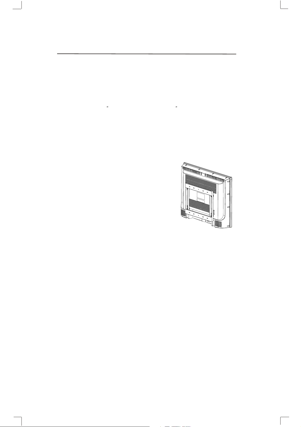
To Remove The Stand Base:
1.Unplug all the cables and cords from your LCD TV.
2.Place the LCD TV face down on a soft and flat surface (blanket,
foam, cloth, etc) to prevent any damage to the display.
3.Remove the screws on the back panel of the TV located near
the bottom so that the base stand can be removed. (See the right
figure)
4.Gently pull the stand away from the display by grasping firmly
to the base.
5.Now the display can fit securely to a mount (sold separately) by
utilizing the mounting holes in the back panel of the display (See
the right figure). Please make sure to read the directions of your
specific wall mount to properly hang the HDTV. Make sure the
wall mount is rated to support at least 65 lbs.
0
Professional mounting kits and installation service are
recommended.
-5-

Connections and Setup
Connections and Setup
Things to Consider Before You Connect
Protect Against Power Surges
Connect all devices before you plug any of their power cords into the wall outlet or power
strip. NEVER plug your TV into an outlet that is controlled by a wall switch.
Turn off the TV and/or device(s) before you connect or disconnect any cables.
Make sure all antennas and cables are properly grounded. Refer to the Important Safety
Instructions at the beginning of the User's Guide
Protect Devices from Overheating.
Don't block ventilation holes on any of the devices. Arrange the devices so that air can
circulate freely.
Don't stack devices.
If you place devices in a stand, make sure you allow adequate ventilation.
If you connect an audio receiver or amplifier, place it on the top shelf so the heated air
from it won't flow around other devices.
Position Cables Properly to Avoid Audio Interference
Insert each cable firmly into the designated jack.
If you place devices above the TV, route all cables down the side of the back of the TV
instead of straight down the middle.
If your antenna uses 300-ohm twin lead cables, do not coil the cables. Also, keep the
twin lead cables away from audio/video cables.
Use Indirect Light
Don't place the TV where sunlight or room lighting will be directed toward the screen.
Use soft or indirect lighting.
Get the Picture
The first part of connecting your TV is to get the picture, also known as the signal. The back
panel of your TV allows you to receive analog and/or digital channels by using the
ANTENNA/CABLE INPUT. See the graphic to the bottom for location of the jack.
-6-

Connections and Setup
Getting Channels
What You Need
Antenna ("rabbit ears") or outdoor antenna with
coaxial cable OR Coaxial cable with cable service
A. Do you have an indoor or outdoor antenna? If not,
go to step B. If so, plug the antenna or coaxial cable from
the wall outlet into the ANTENNA/CABLE INPUT to receive
free off-air local digital and analog channels.
B. Do you have cable? If so, plug the coaxial cable from the
wall outlet into the ANTENNA/CABLE INPUT to receive
your cable channels.
C. Do you have a set-top box? If so, you may need to call your
cable company or satellite service provider. They may use
special cables to allow you to view digital channels.
What You Need To Know
Visit www.antennaweb.org to get help deciding what type of antenna to use to receive the
local digital channels available to you. By entering where you live, this mapping program
tells you what local analog and digital stations are available using a certain antenna.
When you are ready to watch channels, the channel banner displays the type of channel
you're viewing. Look for a D at the bottom of the screen for digital channels; look for an A for
analog channels.
Choose your connection
There are several ways to connect your TV. Please use the following chart to determine
which connection is best for you. Proceed to the appropriate page and connect your TV.
Input Signal Compatibility.
INPUT SIGNAL SUPPORT FORMAT
Ant/Cable 480i, 480p, 720p, 1080i (NTSC, ATSC, and QAM formats)
Composite Video 480i
Component Video (480i, 480p, 720p, 1080i)/60HZ
PC VGA(640X480)@60HZ
SVGA(800X600)@60HZ
XGA(1024X768)@60HZ
WXGA(1280X720)@60HZ
WXGA(1280X768)@60HZ
WXGA(1360X768)@60HZ
HDMI 480i(640x480i) @59.94/60HZ
480p(640x480p)@59.94/60HZ
720p(1280x720p) @59.94/60HZ
1080i(1920x1080i) @59.94/60HZ
1080p(1920x1080p) @59.94/60HZ
DVI VGA(640x480)@60HZ
SVGA(800x600)@60HZ
XGA(1024X768)@60HZ
WXGA(1280x720)@60HZ
WXGA(1280x768)@60HZ
WXGA(1360x768)@60HZ
-7-

Connections and Setup
Video (Basic) Connection
This is an example of a connection using the composite video jack.
Component Video (Advanced) Connection
This is an example of a connection using the Component Video jacks.
-8-

Connections and Setup
Connecting the Device with Composite Video (Basic)
This connection allows you to connect a device that has a Video
Out jack, for example, a DVD player. Using the example of a DVD player:
1. If necessary, connect your cable and/or off-air antenna as
described on page 12.
2. Connect your yellow video cable. Connect a video cable to
the (VID1) Video jack on the back of the TV and to the Video
Output jack on the DVD player.
3. Connect your red and white audio cables. Connect the audio
(red and white) cables to the (VID1) R and L Audio jacks on
the back of the TV and to the Audio Output jacks on the DVD player.
Connecting the Device with Component Video (Advanced)
This connection allows you to connect a device that has Y Pb Pr
jacks, for example, a DVD player. Using the example of a DVD player:
1. If necessary, connect your cable and/or off-air antenna as
described on page 12.
2. Connect your Y Pb Pr component video cables. Connect three
video cables or special Y Pb Pr cables to the COMPONENT
INPUT (CMPT) Y Pb Pr jacks on the back of the TV and to the
Y Pb Pr outputs on the DVD player.
3. Connect your red and white audio cables. Connect the audio
(red and white) cables to the Component Input (CMPT) R and
L Audio jacks on the back of the TV and to the Audio Output
jacks on the DVD player.
Viewing the Picture from the Connected Device
1. Plug in the TV and the device, if they aren't already plugged in.
2. Turn on the TV and the device you want to view, for example
a DVD player.
3. Press the INPUT button on the remote control until you
select VID1 (if connected to the VIDEO INPUT 1 jack) or
YUV (if connected to the YUV jacks) and press OK.
To go back to view TV channels, use the number buttons
to enter the channel you want to view.
Note : If the picture from the DVD player appears black and white and your device is
connected to the VIDEO Input, you might tune to the wrong input. Make sure you press
INPUT until you select VID1 or YUV displayed at the top of the TV's screen.
Note : If the device you're connecting also has Component Video jacks and you have
component video cables, we recommend you use the Component Video (Advanced)
Connection instead. See instructions below.
Note :
If you have connected the devices to your TV, go to page 12 to complete the Initial Setup. To
continue connecting devices, go to the next page.
-9-
Connections and Setup
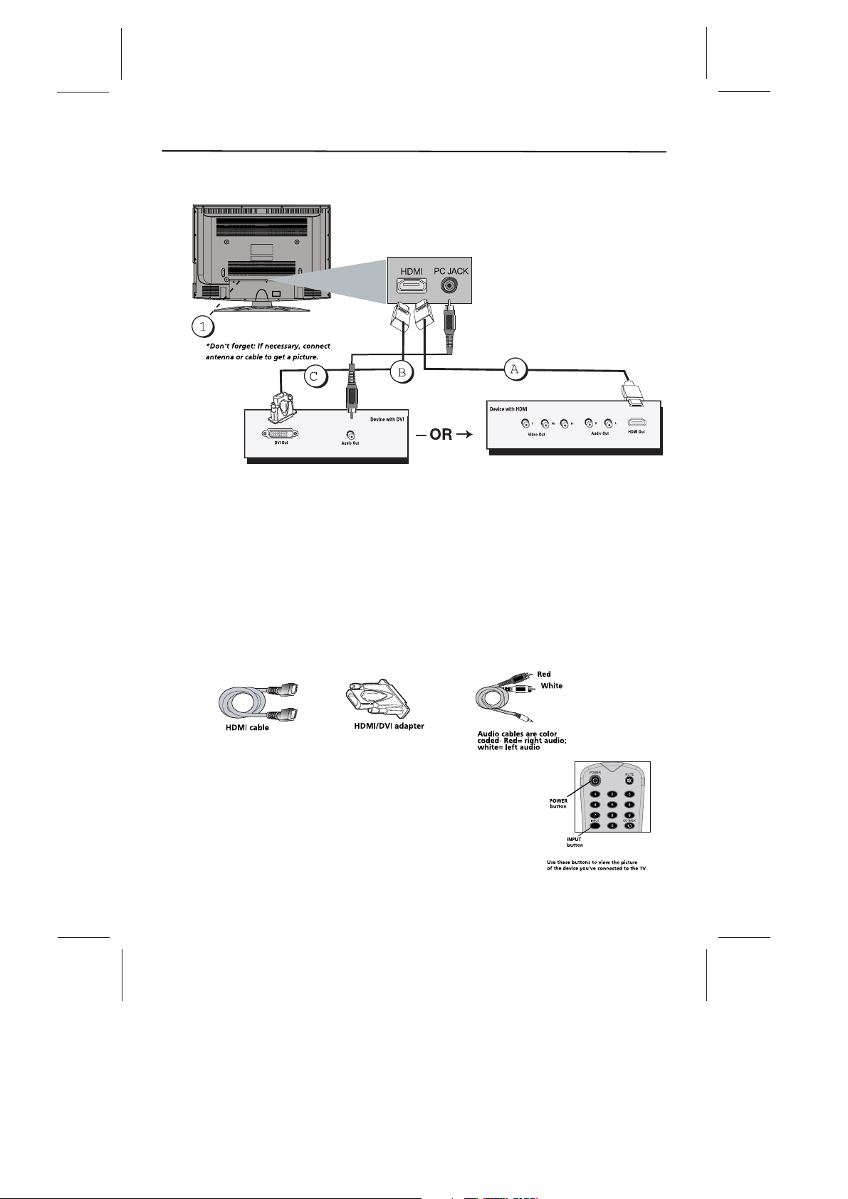
HDMI/DVI Connection
This is an example of a connection using the HDMI1/DVI jack.
Connecting the HDMI Device
High-Definition Multimedia Interface (HDMI) technology is an uncompressed digital
connection that carries both video and audio data by way of an integrated mini-plug cable.
Since HDMI technology is based on Digital Visual Interface (DVI), the jack on the back of
your TV is also compatible with devices that have a DVI output jack. Using the example of a
set-top box:
If your set-top box has an HDMI jack, connect an HDMI cable. Connect an HDMI cable to
the DVI Input jack (or the HDMI jack if it is more convenient) on the back of the TV and to
the HDMI Out jack on the back of the device.
If your set-top box has a DVI jack, connect an HDMI cable and an HDMI/DVI adapter.
1. Connect an HDMI cable to the DVI Input jack on the back of the TV.
2. Attach an HDMI/DVI adapter to the end of the HDMI cable, then connect the adapter to
the DVI Out jack on the set-top box.
3. Since you're using an HDMI/DVI adapter, you need to connect Audio cables to the
Connect a 3.5 mm stereo mini pin cable to the PC AUDIO jack on the back of the TV and
to the R and L audio jacks on the back of the device.
Viewing the Picture from the Connected Device
The device in this connection is connected to the HDMI /DVI jack.
To view this device:
1. Plug in the TV and the device, if they aren't already plugged in.
2. Turn on the TV and the device you want to view, for example
a set top box.
3. Press the INPUT button until you select HDMI and press OK
on the remote control. To go back to view TV channels, use the
Number buttons to enter the channel or press CH+ or CH- buttons.
-10-

Connections and Setup
PC Connecting
This connection allows you to connect to a personal computer.
1. If necessary, connect your cable and/or off-air antenna as described on page 12.
2. Connect your monitor cable. Connect one end of a 15-pin monitor cable to the PC VIDEO
jack on the TV and the other end to the PC's video output jack. Note, if your PC's video
output isn't 15-pin, you'll need an adapter that can connect to a 15-pin monitor cable.
3. Connect your audio cable.
Connect a 3.5 mm stereo mini pin cable (sometimes referred to as 1/8" stereo mini pin) to
the PC AUDIO jack on the back of the TV and the other end to the Audio Output jack on the
PC.
Viewing the PC
1. Plug in the TV and the PC, if they aren't already plugged in.
2. Turn on the TV and the PC.
3. Press the INPUT button until you select PC and press OK on the remote control. To go
back to view TV channels, use the number buttons to enter the channel or press CH+ or CHbuttons.
Note: The maximum resolution is 1366x768/60Hz. Be sure to set your PC to the correct
monitor output setting.
Note :
If have connected the devices to your TV, go to page 12 to complete the Initial Setup.
If you have connected devices to your PC, press the PRESET button on the remote control
until you enter PRESET MENU, select the item PC Sound Source and then use left or right
arrow button to select PC or AV.
-11-
 Loading...