

Page 1

19 /20 LCD Television / Monitor
SLTV-1963A
Owner s Manual
SLTV-2063A
Page 2
The lighting flash with arrow head within a
WARNING
RISK OF ELECTRIC SHOCK
DO NOT OPEN
WARNING: TO REDUCE THE RISK OF ELECTRIC SHOCK DO NOT
REMOVE COVER OR BACK. NO USER-SERVICEABLE PARTS INSIDE.
REFER SERVICING TO QUALIFIED SERVICE PERSONNEL.
WARNING: To reduce the risk of electric shock do not expose this apparatus to rain or moisture and objects
filled with liquids, such as vases, should not be placed on this apparatus.
WARNING:
WARNING:Do not leave any stationary images, patterns, PIP box, or letterbox images on the screen for an extended
period of time. Also, do not display the same stationary patterns frequently. This may result in permanent
ghost images on the display unit. This type of damage is not covered under warranty. Examples of this
type of situation can be but not limited to the following: side bar images, stock market report bars, video
game patterns, closed captioning, shopping channel logo, price display, and letterbox black bars. To
prevent this type of damage, display constant moving images that fill the screen as often as possible.
According to the industrial standards, there are a certain number of defective pixels both bright
and dark that are acceptable. Although we produce panel with more than 99.99 percent active
cells, there still may be some cells that do not produce light or remain lit. For more information,
please contact sales or the technical support.
triangle is intended to tell the user that parts
inside the product are a risk of electric shock
to persons.
The exclamation point within a triangle is
intended to tell the user that important
operating and servicing instructions are in
the papers with the appliance.
CAUTION
Changes or modifications not expressly approved by the party responsible for compliance with the FCC
Rules could void the use s authority to operate this equipment.
,
TV/CATV MODE SELECTION
When shipped from the factory, the TV/CATV menu option is set to the TV mode. If using CATV, set the
menu option to CATV (Cable Television)
IMPORTANT SAFETY INSTRUCTIONS
1.READ INSTRUCTIONS - All the safety and operating
instructions should be read before the unit is operated.
2.RETAIN INSTRUCTIONS - The safety and operating
instructions should be retained for future reference.
3.HEED WARNINGS - All warnings on the unit and in
the operating instructions should be adhered to.
4.FOLLOW INSTRUCTIONS - All operating and use
instructions should be followed.
5.CLEANING - Unplug this unit from the wall outlet
before cleaning. Do not use liquid cleaners or aerosol
cleaners. Use a damp cloth for cleaning the exterior
cabinet only.
6.ATTACHMENTS - The manufacturer of this unit
does not make any recommendations for attachments,
as they may cause hazards.
7.WATER AND MOISTURE - Do not use this unit near
water. For example, near a bathtub, washbowl,
kitchen sink, laundry tub, in a wet basement, or near a
swimming pool.
8.ACCESSORIES - Do not place this unit on an
unstable cart, stand, tripod, bracket, or table.
The unit may fall, causing serious injury, and serious
damage to the unit. An appliance and cart
combination should be moved with care. Quick stops,
excessive force, and uneven surfaces may cause the
appliance and cart combination to overturn.
9.VENTILATION - Slots and openings in the cabinet
back or bottom are provided for ventilation, to
ensure reliable operation of the unit and to protect it
from overheating. These openings should never be
blocked by placing the unit on a bed, sofa, rug, or
other similar surface. This unit should never be
placed near or over a radiator or heat source. This
unit should not be placed in a built-in installation,
such as a bookcase, or rack unless proper ventilation
is provided or the manufacture s instructions have
been adhered to.
10.POWER SOURCE - This unit should be operated
only from the type of power source indicated on the
rating plate. If you are not sure of the type of power
supply to your home, consult your appliance dealer
or local power company. For units intended to
operate from battery power, or other sources, refer
to the operating instructions.
PORTABLE CART WARNING
S3126A
,
1
Page 3

11.POLARIZATION - This unit is equipped with a
polarized alternating current line plug (a plug
having one blade wider than the other). This plug
will fit into the power outlet only one way. This is
a safety feature. If you are unable to insert the
plug fully into the outlet, try reversing the plug. If
the plug still fails to fit, contact your electrician to
replace your obsolete outlet. Do not defeat the
safety purpose of the polarized plug.
12.POWER-CORD PROTECTION - Power supply
cords should be routed so that they are not likely
to be walked on or pinched by items placed upon
or against them, paying particular attention to
cords at plugs, convenience receptacles, and the
point where they exit from the appliance.
13.LIGHTNING - To protect your unit during a
lightning storm, or when it is left unattended and
unused for long periods of time, unplug it from
the wall outlet and disconnect the antenna or
cable system. This will prevent damage to the unit
due to lightning and power line surges.
14. POWER LINES - An outside antenna system
should not be located in the vicinity of overhead
power lines, or other electric light or power
circuits, or where it can fall into such power lines
or circuits. When installing an outside antenna
system, extreme care should be taken to keep
from touching such power lines or circuits as
contact with them might be fatal.
15.OVERLOADING - Do not overload wall outlets
and extension cords as this can result in a risk of
fire or electric shock.
16.OBJECT AND LIQUID ENTRY - Do not push
objects through any openings in this unit as they
may touch dangerous voltage points or short out
parts that could result in fire or electric shock.
Never spill or spray any type of liquid into the unit.
17.OUTDOOR ANTENNA GROUNDING - If an
outside antenna or cable system is connected to
the unit, be sure the antenna or cable system is
grounded to provide some protection against
voltage surges and built-up static charges.
Section 810 of the National Electrical Code,
ANSI/NFPA 70, provides information with respect
to proper grounding of the mast and supporting
structure, grounding of the lead-in wire to an
antenna discharge unit, size of grounding
conductors, location of antenna discharge unit,
connection to grounding electrodes, and
requirements for the grounding electrode.
18.SERVICING - Do not attempt to service this
unit yourself as opening or removing covers may
expose you to dangerous voltage or other
hazards. Refer all servicing to qualified service
personnel.
19.DAMAGE REQUIRING SERVICE - Unplug this
unit from the wall outlet and refer servicing to
qualified service personnel under the following
conditions:
A. When the power-supply cord or plug is
damaged.
B. If liquid has been spilled, or objects have fallen
into the unit.
C. If the unit has been exposed to rain or water.
D. If the unit does not operate normally by
following the operating instructions. Adjust
only those controls that are covered by the
operating instructions, as an improper
adjustment of other controls may result in
damage and will often require extensive work
by a qualified technician to restore the unit to
Its normal operation.
E. If the unit has been dropped or the cabinet has
been damaged.
F. When the unit exhibits a distinct change in
performance, this indicates a need for service.
20.REPLACEMENT PARTS- When replacement
parts are required, be sure the service technician
uses replacement parts specified by the
manufacturer or those that have the same
characteristics as the original part. Unauthorized
substitutions may result in fire, electric shock or
other hazards.
21.SAFETY CHECK - Upon completion of any
service or repairs to this unit, ask the service
technician to perform safety checks to determine
that the unit is in proper operating condition.
22.HEAT - The product should be situated away
from heat sources such as radiators, heat
registers, stoves, or other products(including
amplifiers) that produce heat.
23.NOTE TO CATV SYSTEM INSTALLER - This
reminder is provided to call the CATV system
installer s attention to Article 820-40 of the NEC
,
that provides guidelines for proper grounding and,
In particular, specifies that the cable ground shall
be connected to the grounding system of the
building, as close to the point of cable entry as
practical.
EXAMPLE OF ANTENNA GROUNDING AS PER
NATIONAL ELECTRICAL CODE S2898A
ANTENNA LEAD
IN WIRE
ANTENNA DISCHARGE UNIT
GROUND
CLAMP
E
LECTRIC
SERVICE
EQ
UIP
MENT
NEC - NATIONAL ELECTRIC CODE
(NEC SECTION 810-20)
GROUNDING CONDUCTORS
(NEC SECTION 810-21)
GROUND CLAMPS
POWER SERVICE GROUNDING
ELECTRODE SYSTEM
(NEC ART 250. PART H)
2
Page 4

Table of Contents
TABLE OF CONTENTS
Congratulations
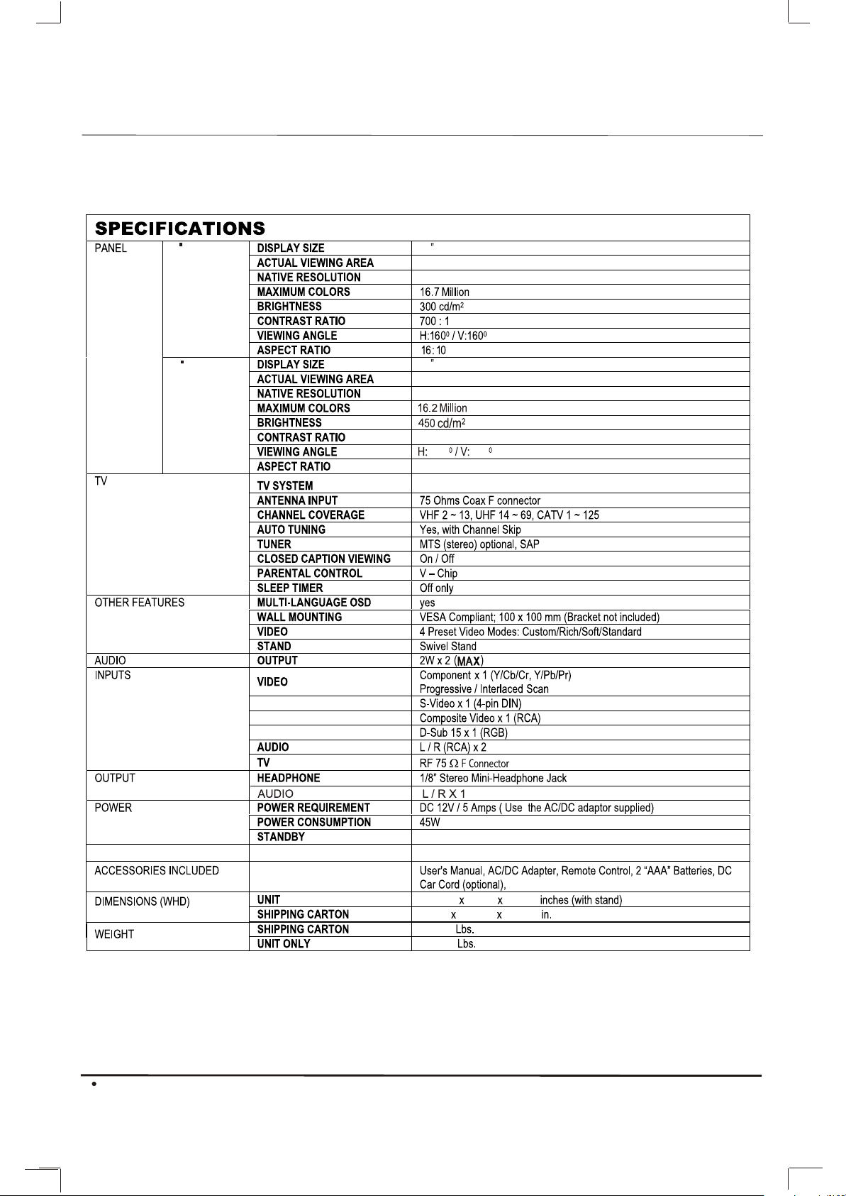
Specifications
Installation
Television Location
Remote Control Battery Installation
Power Source
Combination VHF/UHF Antenna
Optional Equipment Connections
Rear Panel Connectors
Front Control Panel
Remote Control Operation
TV mode
8-11
8-11
4
Function Menu Operation
4
PICTURE
5
V-CHIP
5
Setup menu
5
DTV Setting menu
5
Tune menu
6
PC Setup menu
7
Special Message
7
Service Tips
7
Limited Warranty
12-16
12
12
13
14
14
15
16
17
18-19
3
Page 5
¼ò ½é¼ò ½é
CONGRATULATIONS
Congratulations
Your new TV Monitor/Receiver features a solid state chassis that is designed to give you many years of enjoyment.
It was thoroughly tested and tuned at the factory for best performance.
19
20
19 Color (Diagonal)
408.24 x 255.15mm (H x V)
1440 x 900
20 Color (Diagonal)
433.61 x 249.41 mm (H x V)
1366 x 768
600:1
160 140
16:9
NTSC/ATSC
; ATSC
(For ATV Only)
DTV Build-in yes
Note:
Specification are subject to change without prior notice.
4
< 3W
21-7/16 7-1/16 16-1/4
24-1/4 9-7/16 18-1/2
20-1/4
14-5/16
Page 6

INSTALLATION
Installation
Television Location
Follow these recommendations before deciding the
location of your television.
Avoid excessive sunlight or bright lights,
including reflections.
Keep away from excessive heat or moisture.
Inadequate ventilation may cause internal
component failure.
Fluorescent lighting may reduce remote
control transmitting range.
Keep away from magnetic equipment,
including motors, fans and external speakers.
WARNING: Use this television receiver only with the
cart, stand, tripod, bracket, or table specified by the
manufacturer, or sold with the apparatus. When a cart
is used, use caution when moving the Cart / apparatus
combination to avoid injury from tip-over. In order to
avoid injury to children, never place your television
receiver on a piece of furniture that is capable of being
tilted by a child leaning on it, pulling on it, standing o it,
or climbing on it. A falling television can cause serious
injury or even death.
Remote Control Battery Installation
Procedure
1. Turn the remote control face down. Remove battery
cover by pressing down on the marking on the
cover and sliding it off in the direction indicated.
2. Install batteries matching(+) and(-) polarity signs.
3. Replace the battery cover by sliding in reverse until
the lock snaps.
Note: Incorrect installation can cause battery leakage
and corrosion that will damage the Remote
control.
Precautions
Replace batteries in pair.
Do not mix battery types(zinc carbon with
alkaline).
Do not recharge, heat, short-circuit,
disassemble, or burn batteries.
POWER SOURCE
TO USE AC POWER SOURCE
Use the AC /DV adaptor provided for operation on AC.
Insert the AC cord plug into a standard 110-120V 60HZ
polarized AC outlet.
AC outlet
Wider Hole
and Blade
Requires two AAA batteries(supplied).
Polarized AC Cord Plug (One
blade is wider than the other)
To use Car cord
Use the Car Cord provided for operation on 12V DC.
NOTE:
1.AC/ DC adaptor provided can be connected to
the specified voltage (AC 110 volts 60HZ).
2.If the polarized AC cord does not fit into a nonpolarized AC outlet, do not attempt to file or cut
,
the blade. It is the user s responsibility to have
an electrician replace the obsolete outlet.
3.If you cause a static discharge when touching
the unit, and the unit fails to function, simply
unplug the unit from the AC outlet, wait a few
minutes, and plug it back in. The unit should
return to normal operation.
5
Page 7

INSTALLATION
Combination VHF/UHF Antenna
Combination VHF/UHF Antenna (Single 75 ohm
cable or 300 ohm twin-lead wire)
Connect the 75 ohm cable from a combination
VHF/UHF antenna to the antenna jack.
Combination VHF/UHF Antenna (Separate VHF and
UHF 300 ohm twin-lead)
Connect the UHF twin-lead wire to a combiner (not
supplied). Connect the VHF twin-lead to the 300-75
ohm matching transformer (not supplied). Attach the
transformer to the combiner. Attach the combiner to
the antenna jack.
Separate VHF/UHF Antenna
Connect the 75 ohm cable from the VHF antenna and
the UHF antenna twin-lead to a combiner (not
supplied). Attach the combiner to the antenna jack.
NOTE: If your VHF antenna has a twin-lead wire, use
the 300-75 ohm matching transformer( not supplied),
then connect the transformer to the combiner.
For Subscribers to Basic Cable TV Service
For basic cable service not requiring a converter/
descrambler box, connect the CATV 75 ohm coaxial
cable directly to the antenna jack on the back of the
television.
For Subscribers to Scrambled Cable TV service
If you subscribe to a cable service which requires the
use of a converter/descrambler box, connect the
incoming cable to the converter/descrambler box and
connect the output of the box to the antenna jack on
the back of the television. Follow the connections
shown left. Set the television to the output of the
converter/descrambler box (usually channel 3 or 4)
and use the converter / descrambler box to select
channels.
For Subscribers to Unscrambled Basic Cable with
Scrambled Premium Channels
If you subscribe to a cable service in which basic
cable channels are unscrambled and premium
channels require the use of a converter/descrambler
box, you may wish to use a two-set signal splitter (
sometimes called a two-set coupler )and an A/B
switch box from the cable installer or an electronics
supply store. Follow the connections shown left. With
the switch in the B position, you can directly tune
any nonscrambled channels on your TV. With the
switch in the A position, tune your TV to the output
of the converter/descrambler box (usually channel 3
or 4) and use the box to tune scrambled channels.
Combination VHF/UHF Antenna
Single 75 ohm cable
300 ohm twin-lead wire
Splitter
UHF Antenna
300 ohm twin-lead wire
VHF Antenna
Single 75 ohm cable
300 ohm twin-lead wire
Incoming CATV
Take off the Splitter
Converter/Descrambler
Converter/Descrambler
Splitter
300-75 OHM MATCHING
TRANSFORMER
(not supplied)
300-75 OHM MATCHING
TRANSFORMER
(not supplied)
A
A/B Switch
B
COMBINER
(not supplied)
This television has an extended tuning range and can tune
most cable channels without using a cable company
supplied converter box. Some cable companies offer
premium pay channels in which the signal is scrambled.
Descrambling these signals for normal viewing requires the
use of a descrambler device which is generally provided by
the cable company.
6
Page 8

Optional Equipment Connections
Side Panel Connectors
ANT INANT IN
1 2
AUDIO IN 1AUDIO IN 1
RR LL
VIDEOVIDEO S-VIDEOS-VIDEO
3
4
COMPONENTCOMPONENT
PbPb
YY
5
6
1. Antenna or cable In
2. Video / S-Video Audio Right In
3. Video / S-Video Audio Left In
4. Video In
5. S-Video In
6. Component In
7. Component / PC Audio Right In
8. Component / PC Audio Left In
9. PC In
10. Headphone Jack
11.Audio Right Out
12.Audio Left Out
Rear Panel Connectors
DC 12VDC 12V
1
1. DC 12V In
AUDIO IN 2AUDIO IN 2
RR LL
PrPr
7
HEADPHONE HEADPHONE
PC INPC IN
9
8
10
AUDIO OUTAUDIO OUT
RR LL
11
BASIC CONTROLS AND CONNECTIONS
Front Control Panel
The front control panel can be used to access
menus and switch video mode when the remote control
is not available.
12
228844 55 7733 66
11
1. VOL.- Button
2. VOL.+ Button
3. CH.- Button
4. CH.+ Button
5. Menu Button
6. TV/AV Button
7. Power Button
8. Power Indicator / Remote Sensor
Procedure
Connect equipment as shown to Audio/Video
input jacks.
Select the Video mode by pressing TV/AV button.
Operate optional equipment as instructed in
equipment manual.
Headphone jack: Plug an earphone or monaural
headphones into this jack for private listening.
Note: The ON/OFF indicator LED(red) will light up
when you insert the AC cord into the AC outlet.
7
Page 9

REMOTE CONTROL OPERATION
Remote Control Operation
»ù±¾²Ù×÷»ù±¾²Ù×÷
POWER
Turn on / off.
MUTE
Mute the sound.
DTV
DTV
Enter DTV Setting menu
P.M
P.M
Select desired picture mode.
I/II
AUDIO
I/II
4
7
- /- -
TV/AV
P.M. DTV
2
5
8
0
CH.+
MENU
CH.-
VOL.+VOL.-
I/II
3
6
9
Q.
VIEW
CC
-/---/--
-/--
Select channel digits.
Q.VIEWQ.VIEW
Q.VIEW
Back to previous viewed channel.
SLEEPSLEEP
Set the sleep timer.
Display information of current input.
Select sound mode.
CC
CC
Enter CC setting menu.
TV/AV
TV/AV
Switch to desired input source.
1
2
3
5
6
4
7
8
9
0
Select channel or enter password.
MENU
Display menu function.
CH+
CH-
Channels Up / Down.
VOL-
VOL+
Volume Up / Down
8
Page 10

REMOTE CONTROL OPERATION
TV MODE:
1.POWER Button( )
Press this button to turn the TV on or off.
2. Mute Button( )
Press once to mute the sound, press again to recover
previously set sound level.
2
2
3
1
This button will not work if CC display is switched on.
DTV:Press this button to enter DTV setting menu.
3. Picture Mode Button( P.M )
8
6
14
11
3
4
7
- /-
-
TV/AV
P.M. DTV
5
8
0
CH.+
MENU
CH.-
Q.
VIEW
VOL.+VOL.-
I/II
6
9
CC
7
9
5
13
12
10
4
15
Press this button to select desired picture mode. Four
picture modes are available including Custom, Rich,
Standard and Soft mode.
CUSTOM RICH
SOFT STANDARD
4. Sound Mode Button( I/II )
When stereo program is received, press this button to
switch sound system between mono and stereo. When
sap program is received, press this button to switch
sound system between mono and sap. When stereo
and sap program is received, press this button to
switch among mono, sap and stereo.
5. Closed Captioning Button( CC )
CC Status On
CC Mode Text4
Press this button to enter CC setting menu for analog
input which is shown above if any source except for
DTV is watched. In this menu you can switch on and off
the CC display and select desired CC mode including
CC1, CC2, CC3, CC4, Text1, Text2, Text3 and Text4
mode. CC mode can be set only when CC display is
switched on.
DTV CC Setup menu
CLOSED CAPTION
CLOSED CAPTION SERVICE
CLOSED CAPTION PREFERENCE
Press this button to enter CC setting menu for DTV
(ATSC) if DTV is watched. In this menu DTV CC
service and preference can be set.
Note:
Only the DTV CC service availabce from the DTV
broadcasting can be selected.If there is no signal for
DTV CC service item is not selectable.
9
Page 11

REMOTE CONTROL OPERATION
To quit this menu please press CC button again or
MENU button or it will disappear automatically after
10-second display.
6.TV/AV Button( TV/AV )
2
8
6
14
11
3
4
7
- /-
-
TV/AV
P.M. DTV
2
5
8
0
CH.+
MENU
CH.-
Q.
VIEW
VOL.+VOL.-
I/II
3
6
9
CC
1
7
9
5
13
12
10
4
15
Press this button to select the desired input source
among TV, DTV,Video, S-Video, Componentand
PC. You can press this button to switch among all
available inputs in this menu continuously until desired
input is displayed. Selected input will be switched to
automatically after two seconds.
7.Number (0-9) Button
Press these buttons to enter digits.
These buttons for direct access to use a channel to enter
channel number for both ATV and DTV or enter
password for V-Chip.
8.Digit Button ( )
For ATV, press this button to select one-digit, two-digit
and three-digit channel access.
For example, selecting channel 8, you can press 8 in "-" mode,
press 08 in"--" mode, press 008 in"---" mode.
It can switch channel digit according to user inputs
automatically. For example, current setting is three-digit
option. If two numbers are entered and switch to this
channel, two-digit option is set automatically.
If an invalid channel number is entered, it will keep
displaying current channel.
For DTV, Pressing this button completes physical
number input for channel number and a dot will be
displayed.
10
9.Quick View Button (Q.VIEW )
Press this button to watch the previously viewed channel
for both ATV and DTV.
10.Sleep Timer Button ( )
Press this button to set sleep time.
You can adjust sleep time (in minutes) by pressing the
VOL+/- buttons in the order shown below:
0 10 20 30-----------------120
Page 12

REMOTE CONTROL OPERATION
11.Recall Button( )
2
1
Press this button to display information on current input.
8
6
14
11
3
4
7
- /-
-
TV/AV
P.M. DTV
2
5
8
0
CH.+
MENU
CH.-
Q.
VIEW
VOL.+VOL.-
I/II
3
6
9
CC
7
9
5
13
12
10
4
15
12.Menu Button
Press this button to enter Picture menu or quit from
current menu.
13.Channel Up(CH.+) / Down( CH.-) Button
Press these buttons to select channels in ascending or
descending order for both ATV and DTV or select
available items in a menu.
14.Volume Up(VOL.+) / Down(VOL.-) Button
Press these buttons to increase or decrease volume,
and also to adjust the settings such as
brightness in the Picture menu, Lock On/Off in the
V-chip menu, etc. Volume Increase£¨VOL.+£©button is
also used to confirm your selection or enter next menu.
15.DTV Setting Menu Button(DTV)
Press this button to enter .DTV Setting menu
11
Page 13

Function Menu Operation
Function Menu Operation
CH.+
MENU
CH.-
VOL.+VOL.-
Press MENU button to display Picture menu. You can
browse Picture, V-Chip, Setup, Tune and PC Setup
menu by pressing VOL+/VOL- buttons. Press CHbutton to enter the selected menu and adjust
available settings by pressing VOL+/VOL- buttons
or confirm you selection or enter next menu by
pressing VOL+ button.
Picture menu
In Picture menu, you can press CH+/CH- buttons to
select available items and adjust brightness,
contrast, hue, color and sharpness by pressing
VOL+/VOL- buttons.
Note:
Hue is only available for NTSC system.
Both Hue and Sharpness settings are not
available for PC input.
Press CH- button to enter V-Chip menu if there is
no password or enter Password Check menu
After input password which consists of only
digitals and spaces, press VOL+ button to
confirm. If the password is correct, return to
V-Chip menu. Otherwise Check Password menu
keep displayed and allow you to re-enter the
password. Press MENU button to quit from this
menu forcedly.
Lock
Press VOL+ /VOL- buttons to select On which
switches on V-Chip function or Off which
switches off V-Chip function. If switch off V-Chip
function, video and audio will not be blocked.
Change Password
Press VOL+ button to enter Password Change
menu to re-set V-Chip password.
After enter new password which consists of only
digitals and spaces, press VOL+ to confirm.
Enter the new password again then press
VOL+ button to confirm again. If the same
password is entered twice, Successful will be
displayed to indicate that you have changed
the password successfully. If the passwords are
different, Unmatched is displayed to indicate
that new password is invalid and allow you to
re-enter the new password. Press MENU button
to return to V-Chip menu.
V-Chip menu
You can set parameters on V-Chip
(parental control) in this menu. All settings are
effective for both ATV and DTV.
The default V-Chip Password is set as 1111.
12
TV Rating
Press VOL+ button to enter TV Rating menu
In this menu you can set TV rating. Press
CH+/CH- and VOL+ /VOL- buttons to select
desired rating, block or unblock the selected
rating. B means block and V means view.
Page 14

Function Menu Operation
MPAA Rating
Press VOL+ button to enter MPAA Rating menu
Function Menu Operation
Input your password, press VOL+ to confirm.
If the password is correct, image and volume will
recover. Otherwise image and volume will still
be blocked and above dialog will not disappear.
In this menu you can set MPAA rating. Press
CH+/CH- buttons to select desired rating, block
or unblock the selected rating by pressing
CH+/CH- buttons.
Canada English Rating
Press VOL+ button to enter Canada English rating
menu when CA Eng Rating item is selected
In this menu you can set Canada English rating.
Press CH+/CH- buttons to select desired rating,
block or unblock the selected rating by pressing
VOL+ /VOL- buttons.
Canada French Rating
Press VOL+ button to enter Canada French rating
menu when CA Fr Rating item is selected
In this menu you can set Canada French rating.
Press CH+/CH- buttons to select desired rating,
block or unblock the selected rating by pressing
VOL+ /VOL- buttons.
V-Chip Block
If the program is set to be blocked, black screen
will be displayed and volume is muted.
Following dialog indicates V-Chip works and
allows adults to enter password.
Setup menu
You can change some basic settings of the TV set
in this menu. Press CH- to enter this menu.
Press CH+/CH- buttons to select available items
in this menu and perform corresponding operation.
OSD Language
Multi-Language OSD are supported by this TV set.
You can select desired OSD language by
pressing VOL+/VOL- buttons.
Factory Reset
Select this item, press VOL+ to start Factory
Reset function. It takes a few seconds to recover
back almost all settings with default value except
for the DTV settings.
You can try this function whenever there is
something wrong with the TV set and you can not
fix it.
DTV Setting
Select this item and press VOL+ to enter DTV
setting menu.
OSD HPos and OSD VPos
You can adjust the position of the main menu
includes Picture menu, V-Chip menu etc. Adjust
the position of main menu horizontally through
OSD HPos item and adjust the position of main
menu vertically through OSD VPos item.
Aspect
This function works for all available sources. Select
display aspect ratio between 16:10 and 4:3 mode
by pressing VOL+/VOL- buttons.
13
Page 15

Function Menu Operation
Function Menu Operation
DTV Setting menu
DTV related functions can be reached in this menu.
Antenna level
Press VOL+ button to enter DTV Antenna level
menu.
Antenna level menu
ANTENNA SETUP-DIGITAL
SIGNAL STRENGTH
CHANNEL STRENGTH
Adjust the antenna until
the level is 60 or hige
Signal strength
Current
Max
50
50
Factory Reset
Press VOL+ button to reset DTV settings with
default value.
Note:
It is strongly recommended that you should scan
DTV programs right after reset DTV settings.
Otherwise you can not watch all DTV programs.
Aspect
Only DTV display aspect ratio can be selected
between model and mode2 using this item. Please
choose preferred one.
Auto Scan
Press VOL+ button to start DTV auto scan. It takes
a few minutes. During the auto scan process
please do not terminate it by turning off the TV set.
Otherwise the program information may not be
stored.
This menu assists you to adjust the position and
direction of the antenna so that best signal can be
received. Adjust the antenna until the received
signal strength level is 60 or higher.
Audio Setting
Press VOL+ button to enter DTV Andio Setting
menu.
Audio Setting menu
AUDIO SERVICE
English Stereo Main complete
Digital audio parameters can be set in this menu.
Audio Service
Press VOL+ button to enter Audio Service menu in
which you can select preferred audio service. Totally
six digital audio services are possibly available to
be selected. While actually selectable audio services
depend on what kind of audio service is contained
in current program.
Audio preference
Press VOL+ button to enter Audio Preference menu
in which you can select preferred audio language.
Three kinds of audio language are selectable
including English, Spanish and French. While one
kind of language can not be chosen as primary
language and secondary language at the same time.
CC Setting
Press VOL+ button to enter DTV CC Setting menu.
Tune menu
You can modify settings on TV input in this menu.
All settings in this menu are effective for ATV only.
Press CH+/CH- buttons to select available items
in this menu and perform corresponding operation.
Note:
You can enter this menu only in TV mode.
Color System
Three color systems including NTSC, PAL_M and
PAL_N are supported by this TV set. You can
select AUTO to allow the TV set to detect and set
color system automatically or force the TV set to
display the chosen color system by pressing
VOL+ /VOL- buttons when this item is highlighted.
Once AUTO is selected, system will detect the
color system and force to display according to the
detection result and this item will show which
color system is forced by system while it takes a
little time to finish the automatic detection. Due
to the complicated situation it is not guaranteed
that color system can be detected correctly by the
TV set. Please select proper color system if necessary.
14
Page 16

Function Menu Operation
Function Menu Operation
TV Source
Press VOL+ button to enter TV Source menu.
In TV Source menu, you can switch TV source
among Antenna, Cable(STD), Cable(IRC) and
Cable(HRC) by pressing VOL+ button.
Please make it sure that proper TV Source is
selected before auto scan is started otherwise
programs may not be found and stored.
Skip
Press VOL+/VOL- buttons to switch on or switch
off the skip function. If skip function is on, you can
not watch the corresponding program by pressing
CH+/CH- buttons. While you can watch this
program by entering the channel number directly.
Fine Tune
Try this function if TV image is not good.
The adjustable frequency range is + 625KHz.
Note:
AFT(Automatic frequency tune) function is also
available. TV set will adjust the frequency of
TV signal automatically to obtain the best effect
unless you adjust frequency through Fine Tune
function manually.
Auto Scan
Press VOL+ button to search and store all
available programs automatically.
Note:
TV set will store programs of cable and antenna
systems separately. Connect cable to your TV set,
switch to cable system through TV Source item.
Available programs will be stored through channel
No.1 to channel No. 125. Then Connect antenna to
your TV set, switch to antenna system through
TV Source item. Available programs will be stored
through channel No.2 to channel No. 69.
PC Setup menu
You can modify settings on PC input in this menu
Press CH+/CH- buttons to select available items
in this menu and perform corresponding operation.
Note:
You can enter this menu only in PC input and
there is valid signal for the PC input.
Auto Adjust
Press VOL+ button to start adjust PC settings
automatically. It will take a few seconds to finish
the adjustment including horizontal and vertical
position, phase and clock of the PC image. If you
are not satisfied with the effect, you can adjust
these settings manually through following
functions
HPos and VPos
Adjust the position of the PC image through these
items by pressing VOL+/VOL- buttons. Adjust
the position of PC image horizontally through
HPos item and adjust the position of PC image
vertically through VPos item.
Phase
Adjust the phase of the PC image by pressing
VOL+/VOL- buttons. It will make the image
sharp or blurry
Clock
Adjust the clock of the PC image by pressing
VOL+/VOL- buttons. It will change the width of
the active image of the PC input.
Note:
Supported PC input format includes:
MODE
VGA
SVGA
Resolution
640X480
800X600
Vertical
Frequency
60Hz
60Hz
XGA
1024X768
60Hz
Other formats may be supported by the TV set.
15
Page 17

Function Menu Operation
Function Menu Operation
Special Message:
No Signal
This message indicates there is no signal for
PC input.
If there is no signal for PC input, black screen
will be displayed and above dialog mentions you
to plug PC signal. For all inputs other than PC
input, blue screen will be displayed if there is no
valid input.
Out Of Range
Because of the limitation of the LCD panel, some
picture format can not be displayed normally.
This message indicates that current input exceeds
the display ability of the panel.
Invalid Mode
Due to the limitation of microchips used by the
TV set, some picture format can not be supported
by the TV set. This message indicates that the TV
set can not perform normal image management
for current input format.
Note:
For TV input, only NTSC system is supported.
For Component input, following formats are
supported. 480i@60Hz, 480p@60Hz, 576i@50Hz,
576p@50Hz, 720p@50Hz, 720p@60Hz, 1080i@50Hz,
1080i@60Hz
Auto Configuration
This message indicates that PC automatic
configuration is in process.
After finish PC image adjustment, this
message will disappear.
Image Shrink
This message indicates system is shrinking the
input signal so as it can be displayed although
part of the image will be lost. For some input
formats which can not be displayed normally due
to the limitation of the panel or microchips used
by the TV set, software system will automatically
calculate and delete part of the image and allow
primary part of the image to be displayed.
Note:
Sometimes for some supported input format,
system will also automatically calculate and decide
whether or not should shrink the input image.
During this process, Image Shrinking message is
also displayed. While if system finds that input
format should be supported by the TV set, this
message will disappear and the whole picture
will be displayed.
16
Page 18

»ù±¾²Ù×÷»ù±¾²Ù×÷
Service Tips
Please make these simple checks as
indicated ( ) on the chart for the
respective symptoms and their possible
remedies.
ble
i
s
Symptoms
No picture, no sound
Poor sound, picture OK
Poor picture, sound OK
Weak picture
Blurred picture
Double image
Lines in picture
Distorted picture
Weak reception on some channels
Horizontal bars
Picture rolls vertically
Poor colour
No colour
Misoperation of Remote control
Remote control unit no operation
On Screen Display Control outside the screen
os
P
Service Tips
e
bl
u
o
r
t
on
i
t
t
a
e
t
s
f s
y
l
o
k
ac
obab
b
pr
n
es
,
r
o
wi
r
f OK
ons
i
l,
e
nn
a
s
e
i
d
e
m
Re
on
h
c
c
t
ial
n
er
re
a
e
ff
i
ck
d
ry
T
Che
oo
en
ti
c
nd
i
e
n
if
(
brok
l
a
i
for
r
e
al
i
a
t
er
a
en
i
r
a
ck
o
-
ob
he
C
Re
Pr
e
c
n
ia
l
p
p
a
n
a
s
a
ch
)
u
s
pe
,
y
e
t
ere
f
er
t
in
l
a
oc
l
y
bl
d
A
l
ol
nc
ro
r
ont
c
cont
s
g
n
i
es
s
n
n
t
a
u
t
h
tr
ig
r
on
ine
f
b
c
t
t
t
s
s
s
u
u
u
j
j
d
dj
A
A
r
u
lo
co
et
ing
s
t
s
y
tl
ca
c
d
e
ol
r
ont
c
t
tion
a
t
s
k if
c
e
Ch
rr
oa
l
o
co
br
r
nt
is
is
co
em
r
t
o
u
s
o
y
l
s
on/
f
f
i
i
co
t
k
s
ck
c
u
e
j
h
he
d
A
C
C
t
ni
u
ol
r
t
on
"
c
on
e
"
t
o
is
ch
rem
it
in
w
s
s
f
e
f
eri
t
t
ba
ck
he
C
17
Page 19

18
Page 20

Skyworth Electronics Inc.
Skyworth Electronics Inc.
1312 John Reed Court,
1312 John Reed Court,
City of Industry, CA 91745
City of Industry, CA 91745
Phone: 626-336-3698
Phone: 626-336-3698
Fax: 626-336-3238
Fax: 626-336-3238
Email: service@skyworth.com.hk
Email: service@skyworth.com.hk
Http: www.skyworth.com.hk
Http: www.skyworth.com.hk
19
 Loading...