

Page 1

USER’S MANUAL
USER’S MANUAL
LED HDTV/DVD COMBO
SLC-1519A-3S
SLC-1919A-3S
SLC-2219A-3S
MODEL
SKYWO RT H EL ECTRONI CS ,I NC
Phone : 62 6 33 6-3698
FAX: 626 3 36 -3 23 8
Email : sk yw orthsal es @v erizo n. ne t
1312 jo hn R ee d Court
City of I nd us try, CA 91745
Page 2
Warning
To prev ent fir e and/o r elect ric sho ck, do no t use thi s plug wi th an ext ensio n
cor d, rece ptacl e or othe r outle t unles s the bla des can b e fully i nsert ed to
pre vent bl ade exp osure . Do not ex pose th is appl iance t o rain or m oistu re.
Important Safety Instructions
Rea d these i nstru ction s.
Kee p these i nstru ction s.
Hee d all war nings .
Fol low all i nstru ction s.
Ple ase, un plug th e T V power c ord whe n the fol lowin g co ndi ti ons o cc ur:
-Wh en ther e is a thun derst orm (Pl ease, p ull out t he powe r cord an d anten na).
-Wh en clea ning th e T V set.
-Wh en the TV s et i s not u se d for a l on g tim e.
Do no t use cor rosiv e depur ative w hen cle aning t he TV set .
Do no t put the T V se t und er d ire ct s unl ig ht or n ea r hea t.
Do no t put a hea t sourc e, such a s a candl e or heat er, on top o f or near t he TV set .
Lea ve plen ty of spa ce (al le ast 10c m) arou nd the TV s et f or ve nt ila ti on.
Pla ce the TV s et a way f ro m whe re i t can b e ru ine d by r ain o r wa ter ( su ch as n ea r a
win dow).
Don 't put a co ntain er with l iquid ( such as a v ase) on t op of the T V se t.
Do no t move th e T V set whe n the pow er is on.
Do no t touch , push or s cratc h the sur face of t he TV set w it h har d ma ter ia ls or i te ms.
Whe n T V surfa ces are d irty, pl eas e us e a wet c ot ton c lo th or s of t clo th w ith n on cor rosiv e clean ers
to cl ean it ca reful ly. Don´ t us e ace to ne, t ol uen e or a lco ho l to cl ea n the T V set .
Be awa re and ca ref ul of moi stu re, wh ich ca n dama ge inn er ele ctr onic c ompo nen ts.
Whe n cond ense d
moi sture i s prese nt, the T V sc ree n ma y app ea r blu rr y or sp ot ty.
It is r ecomm ended t hat a tec hnici an inst all the T V se t on a wa ll , if su ch p lac em ent i s
des ired.
An in corre ct wall i nstal latio n will be u nsafe a nd haza rdous .
Do not le t chil dre n clim b on or pla y arou nd the TV se t to avoi d fall s, col lis sio ns,
dam ages a nd inj urie s.
Do no t hit the T V pa nel w it h har d ob jec ts t o pre ve nt da ma ges .
Do no t cover t he TV set w it h bla nk ets o r ot her o bj ect s wh en it i s co nne ct ed to a
pow er sour ce to pre vent ov erhea ting an d fire.
Batte ries shal l not b e exposed to excessi ve heat such as sunshine , fire or the l ike.
Mai ns plug i s used as d iscon nect de vice fr om the ma ins, th e disco nnect
dev ice sha ll rema in read ily ope rate.
App aratu s with cl ass I con struc tion sh all be co nnect ed to a mai ns sock et
out let wit h a prote ctive e arthi ng conn ectio n.
Safety Information
AVIS RISQUE DE CHOC ELEC TRIOUE/NE PAS OUVRIR
Page 3
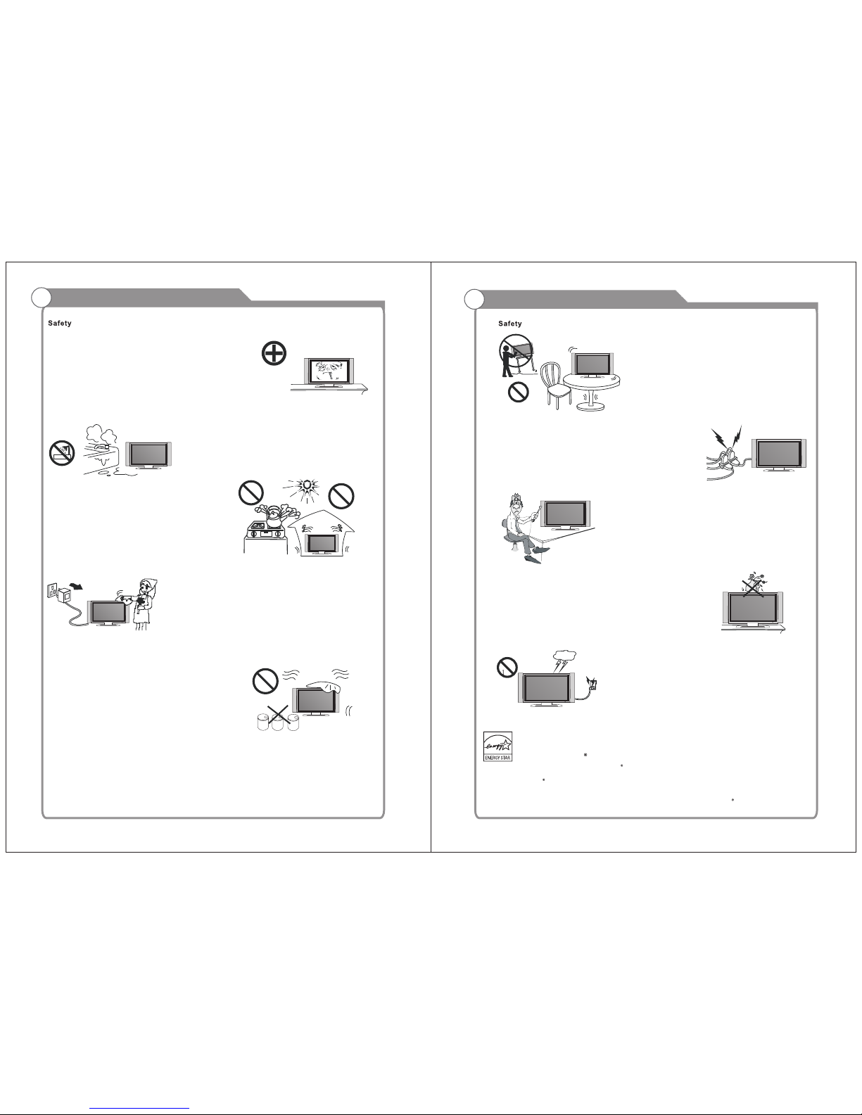
Important Safety PrecautionsImportant Safety Precautions
Do not pl ac e the pow er cor d or oth er cab les
acr oss a wal kway in c as e i t is tram ple d o n. Do
not ove rlo ad the powe r cor d or powe r soc ket.
Whe n the pow er plug i s used to d iscon nect an d
con nect th e de vic e, it sho uld e as ily i nt o the
pow er sour ce.
Do no t place t he LED TV o n an u nst ab le
sur face.
Do no t dis as sem bl e the ba ck co ve r, as it
con tains h igh vol tages i nside a nd will c ause
ele ctric shoc k. O nly q ual if ied profe ssion als
sh ou ld co nd uc t in ter na l a dj us tm en ts ,
mai ntena nce, an d check s.
The TV set sho ul d n ot be s ubj ec ted to
wat er d rop le ts, v apo r, or spl as h. T his
equ ipmen t shoul d not be pl aced on o bject s
fil led wi th li qui ds . Do no t pl ace fl ame
sou rces, suc h as l it ca ndles , on or ne ar th e
LED TV. Pl eas e, pu ll out the pow er pl ug
and conta ct a ft er s ale s su pp ort if t her e are
abn ormal o bject s or wate r in the TV.
Pul l ou t the po wer cor d and an ten na cable
dur ing ele ctric al stor ms so the L ED TV is no t
dam aged by el ect ri cal su rg es. Ke ep al l
peo ple a wa y f rom the a nt enn a c able durin g
ele ctric al stor ms.
Ple ase, im media tely pu ll out th e AC p ow er
plu g
fro m adapt er if the re is an ab norma l sound o r
sme ll or the L ED TV has s ou nd bu t no p ict ur e,
and c ontac t after s ales su pport .
The L ED TV sho ul d be ke pt f ree f ro m rai n,
moi sture a nd dust t o preve nt elec trica l
sho ck and
sho rt circ uits. D o not cov er the ve ntila tion
ope nings w ith tab le clot hes, cu rtain s,
new spape rs, etc .
The L ED TV sho ul d be ke pt f rom h igh
tem perat ure heatin g sou rce s or dir ect
sun light . Go od ve nti la tio n is req uired .
All ow 10 cm. bet wee n the LE D TV and
oth er appl iance s or buil t-in ca binet w alls.
Whe n yo u w ip e t he f ron t cab ine t, pl eas e
mak e su re the powe r plu g is pul led out and
use a soft , dry, lint -f ree cl oth an d handl e i t
wit h car e. Do not repe ate dl y w ipe the p ane l,
nor s crape , tap or st rike th e panel w ith a har d
obj ect.
Do n ot w ipe the LED T V wi th a ny p etr ol,
che mical o r alcoh ol base d solve nts as it
wil l lead t o pro du ct da mage o f the p anel
and c abine t.
ENERG Y STAR Qua li fi catio n.
Thi s produ ct has ea rned th e ENERG Y STAR for me eting U .S. Fed eral en ergy ef ficie ncy gui delin es as set
by th e Depar tment o f Energ y and Env ironm ental p rotec tion ag ency.
The ENE RGY STAR progr am exists to pr ovide ene rgy saving g uidelin es and help pro mote ener gy efficie nt
prod ucts and pra ctices. Ch anges to cer tain feat ures, set tings and fu nctions of t his TV can chan ge and/or
inc rease i ts powe r consu mptio n.
As- shipp ed mode i s the mod e in whic h the pro duct qu alifi es for EN ERGY STAR .
Page 4
Table of Contents
Table of Contents
Troubleshooting
27
28
25
26
Connecting Digital Audio System
Connecting Amplifier/DVD Home Theater
Connecting DVD Player/Set-Top Box via HDMI
Connecting S-VIDEO
Connecting a Headphone
Introduction
Features
Specifications
General Description
Overview of front and side panel
Overview of back panel
External Connection
Connecting VCR
Connecting DVD Player/Set-Top Box via HDMI
Connecting PC
Supporting signals
Basic operation
Turning the TV On and Off
3
4
5
5
11
11
19
19
18
6
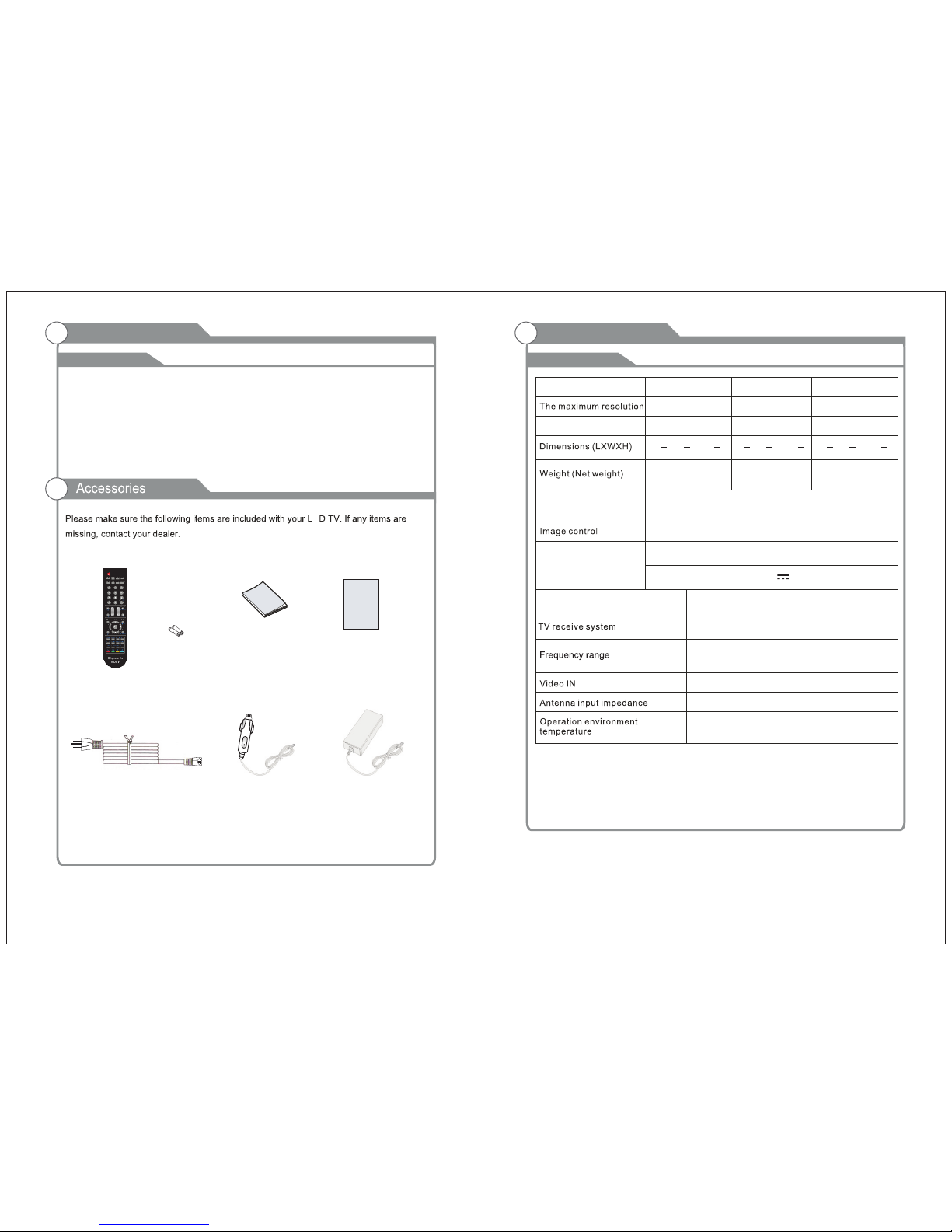
Accessories
3
Antenna connection
10
7-9
10
14
15
16
17
18
12
13
BAS IC OPER AT ION
Pic ture
Aud io
Tim e
Set up
Loc k
Menu system introduction
20
20
21
21
22
22
23-24
Picture defects and the reason
1
2
DVD O PER ATIO N
DVD S etu p Men u
Page 5
Input terminals used for external equipment connection
Introduction
Features
E
Note:
1. In case of any design change, a notice will not be released.
Introduction
W arnings
Specifications
One ANTENNA input
One Computer VGA/PC inpu t
One
HDMI input
One AV input
One USB(only update) input
One EARPHONE output
One PC Audio input
3
4
Fine digital control
NTSC3.58
75W (Unbalance)
NTSC System, ATSC System
Antenna: 2~69; Cable: 1~135 (Analog: 1-125,
Digital: 1-135)
0 C-40 C
o
Adapter requirement
Model
Power Consumption
24W
AC 10 0-240 V, 5 0/6 0H z
1366X768
SLC-1519A-3S
Qui ck Setu p Guide
Quick se tup Gui de
Man ual
Ins truct ions
SLC-1919A-3S SLC-2219A-3S
1366X768 1920X1080
32W 2W4
IN PUT
OUT PUT
DC: 1 2V 3A/5 A/5A
Display screen type Color active matrix LED display
Sound output(Max)
AdapterCar charger cable
Power Cord
Remote Control &
Batteries (AAAx 2)
One COAXIAL out put
One YPbPr input
One L/R Audio output
One S-VIDEO input
6.6 lbs 7.7 lbs 9.4 lbs
2 x 5W
15 Dx6 Wx12 H
43424
2
18 Dx6 Wx13 H
424
1
8
3
21 Dx7 Wx15 H
21
8
1
88
o
Page 6
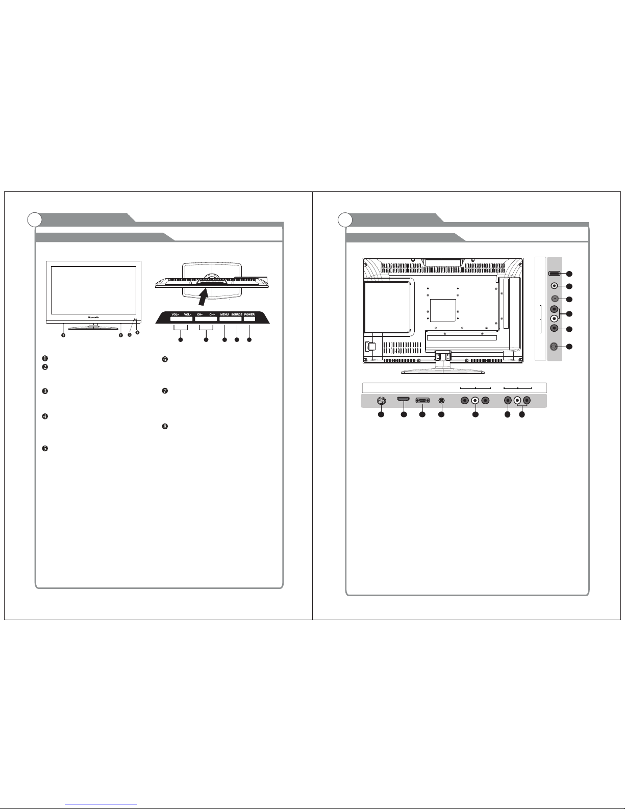
General Description
Overview of front and side panel
General Description
Overview of back panel
5
6
SPEAKER
REM OTE CON TRO L SEN SOR
If an o ption al remo te cont rol is al lowed ,
aim i t towar ds th is s pot o n the TV.
POWER INDICATOR
Green: In power on mode.
Red: In standby mode.
Toggles between all the available input
sources ( TV, AV, S-VIDEO, COMPONENT,
CH+/ Press to change channels.
In the on-screen menu, use the CH +/ buttons as up/down arrow buttons.
VOL+/ Press to increase or decrease the volume.
In the on-screen menu, use the VOL +/ buttons as left/right arrow buttons.
POWER
Press POWER button to toggle between
and standby mode.normal
MENU
Press to see an on-screen menu of your
TV's features.
SOU RCE
4
5
6
7
8
HDMI 1
IN
VGA
IN
PC
AUDIO
IN
DC 12V
IN
Pr
Pb
Y
IN
1 2
3
4
5
RF
IN
EARPH ONE
OUT
USB
R
L
COAXI AL
OUT
10
11
12
13
R
L
VIDEO
IN
9
6
7
8. S- VIDEO
Con nect an S -VIDE O signa l from a
cam corde r or VCR. ..
9. CO AXIAL
10.
11.R F
12. EARPH ONE
13. USB
USB i nput
Con nect to a D igita l Au di o dev ic es.
AUD IO OUT
Con nect to t he audi o outpu t jacks
on yo ur ampl ifier /home t heate r.
Con nect to a n anten na or cab le
NTS C & ATS C.
Con nect a se t of phon e for pri vate
lis tenin g
1. PO WER( ) inp ut
2. HD MI
3.
4. PC A UDI O
5.
6.
DC 12 V
Aud io inpu t for ext ernal d evice s
7. S- VIDEO
Con nect to t he HDMI j ack of a de vice
wit h an HDMI o utput .
VGA /PC IN
Con nect to t he vide o outpu t jack on
you r PC.
COM PONEN T
Con nect Co mpone nt vide o.
COM POSIT E VIDEO
Vid eo i npu t fo r ext er nal d ev ice s, s uch
as a ca mcord er or VCR .
COM POSIT E
COM PONEN T A UDI O
Aud io inpu ts for ex terna l devic es.
DVD, HDMI, VGA)
S-VID EO
IN
8
Page 7

7
8
New s,
Mus ic, Mov ie, Spo rts and C ustom .
Viv id, Sof t, Cust om.
Pre ss to tur n ON/Of f close d capti ons.
16: 9, Lett er Box, P anora ma, 4:3 .
Page 8

x x
Antenna connection
Antenna input impedance of this unit is 75ohm. VHF/UHF 75ohm coaxial cable can be
connected to the antenna jack directly, if the antenna cable is 300ohm parallel flat feeder
cable, you need to use the 300ohm/75ohm converter to connect the antenna cable to the
antenna jack. For details Please refer to the following drawing.
Use a 75ohm - 300ohm converter
300ohm coaxial cable
Antenna feeder
ANT IN
75ohm coaxial cable
Antenna cable
Antennas with 300 ohm flat twins Leads
Antennas with 75 Round Leadsohm
9
10
Page 9

RF
IN
EARPH ONE
OUT
USB
R
L
COAXI AL
OUT
S-VID EO
IN
HDMI 1
IN
VGA
IN
PC
AUDIO
IN
DC 12V
IN
Pr
Pb
Y
IN
R
L
VIDEO
IN
External Connection
Connecting VCR
External Connection
Connecting DVD Player/Set-Top Box
11
12
These instructions assume that you have already connected your TV to an antenna or a
cable TV system. Skip step 1 if you have not yet connected to an antenna or a cable
system.
Follow the instructions in Viewing a VCR or Camcorder Tape to view your VCR tape.
Each VCR has a different back panel configuration.
When connecting a VCR, match the color of the connection terminal to the cable.
We recommend the use of cables with a Ferrite Core.
1. Unplug the cable or antenna from the back of the TV.
2. Connect the cable or antenna to the ANT IN terminal on the back of the VCR.
3. Connect an RF Cable between the ANT OUT terminal on the VCR and the ANT IN
terminal on the TV.
4. Connect a Video Cable between the VIDEO OUT jack on the VCR and the VIDEO IN
jack on the TV.
5. Connect Audio Cables between the AUDIO OUT jacks on the VCR and the AUDIO L and
AUDIO R jacks on the TV.
If you have a mono (non-stereo) VCR, use a Y-connector (not supplied) to hook up to
the right and left audio input jacks of the TV. If your VCR is stereo, you must connect
two cables.
VCR Rear Panel
Audio Cable (Not supplied)
Video Cable (Not supplied)
RF Cable (Not supplied)
and the AUDIO OUT jacks on the DVD player.
the TV and the COMPONENT [Y, PB, PR] jacks on the DVD player.
The rear panel jacks on your TV make it easy to connect a DVD to your TV.
Component video separates the video into Y (Luminance (brightness)), Pb (Blue) and Pr
(Red) for enhanced video quality.
Be sure to match the component video and audio connections.
For example, if connecting the video cable to COMPONENT IN, connect the audio
cable to COMPONENT IN also.
Each DVD player/STB has a different back panel configuration.
When connecting a DVD player/STB, match the color of the connection terminal to the
cable.
We recommend the use of cables with a Ferrite Core.
1. Connect a Component Cable between the COMPONENT IN [Y, PB, PR] jacks on
2. Connect Audio Cables between the COMPONENT IN [R-AUDIO-L] jacks on the TV
Audio Cable (Not supplied)
Component Cable (Not supplied)
DVD Player/Set-Top Box
RF
IN
EARPH ONE
OUT
USB
R
L
COAXI AL
OUT
S-VID EO
IN
HDMI 1
IN
VGA
IN
PC
AUDIO
IN
DC 12V
IN
Pr
Pb
Y
IN
R
L
VIDEO
IN
Page 10

Digital Audio System
External Connection
13
14
Connecting Digital Audio System
The rear panel jacks on your TV make it easy to connect a Digital Audio System to your TV.
5.1 CH audio is possible when the TV is connected to an external device supporting 5.1
CH.
We recommend the use of cables with a Ferrite Core.
1. Connect an COAXIAL Cable between the SPDIF jacks on the TV and the Digital Audio
jacks on the Digital Audio System. When a Digital Audio System is connected to the Input
SPDIF terminal: Decrease the gain (volume) of the TV, and adjust the volume level with
the system's volume control.
COAXIAL Cable (Not supplied)
Digital Audio System
Audio Cable (Not supplied)
Each external input source device has a different back panel configuration.
When connecting an external device, match the color of the connection terminal to the
cable.
We recommend the use of cables with a Ferrite Core.
1. Connect Audio Cables between the AUDIO L and R OUT on the TV and AUDIO IN [R AUDIO-L]on the Amplifier/DVD Home Theater.
When an audio amplifier is connected to the AV OUT [R-AUDIO-L] terminals: Decrease
the gain (volume) of the TV, and adjust the volume level with the Amplifier's volume control.
External Connection
Connecting Amplifier/DVD Home Theater
RF
IN
EARPH ONE
OUT
USB
R
L
COAXI AL
OUT
S-VID EO
IN
HDMI 1
IN
VGA
IN
PC
AUDIO
IN
DC 12V
IN
Pr
Pb
Y
IN
R
L
VIDEO
IN
RF
IN
EARPH ONE
OUT
USB
R
L
COAXI AL
OUT
S-VID EO
IN
HDMI 1
IN
VGA
IN
PC
AUDIO
IN
DC 12V
IN
Pr
Pb
Y
IN
R
L
VIDEO
IN
Page 11

External Connection
Connecting DVD Player/Set-Top Box via HDMI
This connection can only be made if there is a HDMI Output connector on the external
device.
What is HDMI.
HDMI, or high-definition multimedia interface, is a next-generation interface that enables
the transmission of digital audio and video signals using a single cable without
compression.
Multimedia interface is a more accurate name for it especially because it allows multiple
channels of digital audio (5.1 channels).
The difference between HDMI and DVI is that the HDMI device is smaller in size, has the
HDCP(High Bandwidth Digital Copy Protection) coding feature installed, and supports
multi-channel digital audio.
Each DVD player/STB has a different back panel configuration.
We recommend the use of cables with a Ferrite Core.
1. Connect an HDMI Cable between the HDMI connector on the TV and the
HDMI connector on the DVD player/Set-Top Box.
HDMI Cable (Not supplied)
DVD Player/Set-Top Box
External Connection
Connecting PC
Each PC has a different back panel configuration.
The HDMI jacks do not support PC connection.
We recommend the use of cables with a Ferrite Core.
1. Connect a D-Sub Cable between RGB/PC IN connector on the TV and the PC output
connector on your computer.
D-Sub Cable (Not supplied)
PC
PC AUDIO Cable (Not supplied)
2. Connect the PC audio input jackc on the TV
15
16
RF
IN
EARPH ONE
OUT
USB
R
L
COAXI AL
OUT
S-VID EO
IN
HDMI 1
IN
VGA
IN
PC
AUDIO
IN
DC 12V
IN
Pr
Pb
Y
IN
R
L
VIDEO
IN
RF
IN
EARPH ONE
OUT
USB
R
L
COAXI AL
OUT
S-VID EO
IN
HDMI 1
IN
VGA
IN
PC
AUDIO
IN
DC 12V
IN
Pr
Pb
Y
IN
R
L
VIDEO
IN
Page 12

External Connection
136 0X768
192 0X108 0
Not e: only 2 2” can su pport t he reso lutio n of 1920 x1080
USB
DateTrave r
Headphone Cable
Connecting a Headphone
Supporting signals
External Connection
Connecting S-VIDEO
Con nect th e S-VID EO outp ut of the D VD or VCR t o the S-V IDEO in put on th e set.
The p ictur e quali ty is imp roved , compa red to co nnect ing a reg ular VC R to the
vid eo inpu t.
Con nect th e Au di o out pu t of th e DV D or VC R to t he Aud io i npu t ja cks o n th e set
usi ng the RC A ca bl e.
Sel ect S-V IDEO in put sou rce wit h using t he SOUR CE butt on on the r emote
con trol.
S-VIDEO
AV RL
DVD
17
18
RF
IN
EARPH ONE
OUT
USB
R
L
COAXI AL
OUT
S-VID EO
IN
HDMI 1
IN
VGA
IN
PC
AUDIO
IN
DC 12V
IN
Pr
Pb
Y
IN
R
L
VIDEO
IN
RF
IN
EARPH ONE
OUT
USB
R
L
COAXI AL
OUT
S-VID EO
IN
HDMI 1
IN
VGA
IN
PC
AUDIO
IN
DC 12V
IN
Pr
Pb
Y
IN
R
L
VIDEO
IN
Page 13

Turning the TV On and Off
Basic Operation
Pre ss SOUR CE butt on to dis play th e input s ource l ist;
Pre ss ▼ / ▲ butt on to sel ect the i nput so urce yo u want to w atch;
Pre ss ▶ butt on to ent er the in put sou rce;
Adjust the OSD Screen
OSD Menu Operations
2. Press
button on the LED TV.
3. Normal picture will be displayed on the screen after
6 seconds. If no signal input, "No Signal" will be
displayed on the screen.
4. If temporary POWER off is required, press
button on the LED TV.
5. If you want to completely switch off the power for this unit, unplug the power cord plug
for this unit.
6. After switching off the unit, you should turn on the TV again at least 5 seconds later.
Status indication lamp
Green: In power on mode.
Red: In standby mode.
Auto power off
If there is no signal input in any Mode, the TV will automatically accesses the standby
state in about 15 minutes.
Memory before turning TV off
The settings of picture and the preset channels will be memorized at turning off the unit.
When being started up again, the unit will work according to the mode set before being
turned off.
1. How to turn the TV on or off
19
20
1. After attaching cable to either an antenna or a cable service, insert the power cord plug
into a polarized AC outlet.
INPUT SOURCE
TV
AV
PC
HDMI
DVD
Component
S-VIDEO
BASI C OPERATIO N
L
Chan nel
Air/C able Ai r
Auto Sc an
Favor ite
Show/ Hide
Chann el No.
Chann el Labe l
DTV Sig nal Bad
Auto Scan
Digital channel only
Analog channel only
MENU
ENTER
Scan all channels
Press MENU button to display the main menu.
Press◄ / ► button to select CHANNEL in the main menu, it will highlight the first option.
Air /Cabl e
pre ss ENTE R butto ns to sel ect it Ca ble or Air.
AUTO S CAN
Aut o Tu ning ca n find ou t all effe ctive c hanne l autom atical ly.
Pre ss ▼/▲ to sele ct Auto Tu ning, t hen pre ss ENTE R to start
aut o search ing.
If yo u want to st op searc hing , press EX IT.
CHAN NEL
ENTER
Page 14

OSD Menu Operations OSD Menu Operations
21
22
Adjust the OSD Screen
L
Picture
Pictu re Mode S tanda rd
Color M ode Nor mal
Zoom Mo de Norm al
3DNR We ak
DLC On
PIC TURE ME NU
Pre ss MENU to d ispla y the mai n menu, a nd pres s ◄ /► to sele ct the Pi cture M enu.
Hig hligh t the item a nd pres s ▼/▲ to sele ct corre spond ing sub -menu .
Pic ture Mo de: Dyn amic/ Standa rd/So ft/ Pers onal.
Col or mode :This i tem can a djust th e satur ation of t he colo r based o n your ow n like.
Zoo m mode: Fo ur sele ctabl e Zoom Mo des, No rmal, Zo om, Cin ema, Wi de .
3DN R: Use d for the n oi se r educt io n ad justm en t to g et a b ett er i ma ge effe ct s.
DLC : Dyna mi c brigh tn es s co ntr ol
Press MENU button to display the main menu.
Press◄ / ► button to select PICTURE in the main menu, it will highlight the first option.
AUD IO MENU
Pre ss MENU to d ispla y the mai n menu, a nd pres s ◄ /► to sele ct the So und Men u.
Equ alizer : A djust a udio fr equen cy band .
MTS : Set the M TS (ATV mod e).
Dig ital Ou tput: P ress ▼ but ton to hi ghlig ht Digit al Outp ut. the n press t he enter b uton to
sel ect it .
Sur round : S urroun d effect o n or off.
Aud io Only : Audio O nly effe ct on or of f.
AVC: W hen set t he AVC on, q uick vol ume cha nge wil l be smoo thed.
PICT URE
AUDI O
Press MENU button to display the main menu.
Press◄ / ► button to select AUDIO in the main menu, it will highlight the first option.
L
Audio
Equal izer Pe rsona l
Digit al Outp ut PCM
Surro und Off
Audio O nly Off
AVC Off
MTS STE REO
TIME
Press MENU button to display the main menu.
Press◄ / ► button to select TIME in the main menu, it will highlight the first option.
L
Time
Sleep T imer Of f
Time Zo ne Atlan tic
DST Off
Time Fo rmat 24 -hour
Auto Sy nc On
Clock 2 012/1 /1 12:0
WakeU p 2012/ 1/1 12: 0
TIM E MENU
Pre ss MENU to d ispla y the mai n menu, a nd pres s ◄ /►
Sle ep Time r: Sele ct the ti me in min utes( 5min, 10min ,15min ,30mi n,60m in,90 min,1 20min ,
180 min,2 40min ,Perso nal) th at you wan t the TV to s hut off a utomat icall y after yo u set the
tim e. Canc el by sett ing it to O ff.
Tim e Zone: S et to choo se the ti me belt .
DST: Pr ess ENT ER to sel ect the D ST on or off.
Tim e Format : Set to ch oose ti me disp lay form at
Aut o Sync: Sy nchro nous au tomati c
Clo ck:Pr ess ENT ER to set ti me.
Wake Up : Endin g the sta te of slee p
to se lect th e Time Me nu.
SETU P
L
Setup
Menu La nguag e Engli sh
Transp arenc y 25%
Close d Capti on
Resto re Defa ult
Setup W izard
Blue Sc reen Of f
Press MENU button to display the main menu.
Press◄ / ► button to select SETUP in the main menu, it will highlight the first option.
SET UP MENU
Pre ss MENU to d ispla y the mai n menu , an d press ◄/► to se lect th e Set p Me nu.
Men u Langu age: Se t the OSD d isplay l angua ge. (En glish / Frenc h/ Span ish)
Trans paren cy: Set t ranspa rency o f OSD.
Clo sed Cap tion: S et to hid e the capt ion
Rest ore Defa ult: Re call th e defaul t settin g.
Set up Wizar d: Inst allati on guid e.
Blu e Scree n: Set the b ackgr ound co lor to bl ue or bla ck when n o input s ignal .
u
Page 15

OSD Menu Operations OSD Menu Operations
23
24
LOCK
Press MENU button to display the main menu.
Press◄ / ► button to select LOCK in the main menu, it will highlight the first option.
L
Lock
Paren tal Con trols ___
Pre ss MENU b utton to d ispla y the main m enu.
Pre ss butt on to sel ect Loc k in the ma in menu . It will h ighli ght the fi rst opt ion.
Ent er the cod e 0000 to e nter th e parent al menu ( see the p ictur e below) ,
or pr ess MEN U to cance l.
◄ / ►
L
Lock
Chang e Passw ord
Syste m Lock On
Input B lock
US
Canad a
RRT Set ting
Reset R RT
CHA NGE PASSW ORD
Press ENTE R but ton and enter a ne w 4 digit pas sword.
SYST EM LOCK
Pre ss ENTE R to selec t the sys tem lock o n or off.
Unrat ed Lock O ff
UNR AT ED LOCK
Pre ss ENTE R to selec t the Unr ated loc k on or off.
Enter Old Password
Clear Cancel
Enter New Password
Confirm Password
CAN ADA
Press ENTE R but ton for to ente r to CANA DA rat ings menu, which contain s two sub -menus:
Can ada Eng lish an d Canad a Frenc h.
Adjust the OSD Screen
US
Pre ss ENTE R button f or to ente r to US rati ngs men u, whic h contai ns two su b-men us:
MPAA Ra ting an d TV Rati ng.
INP UT BLOC K
HDM I PC )
pre ss◄/►
Pre ss ENTE R to displ ay the In put Blo ck , AVPres s ▼ / ▲ button t o selec t (TV、 、
Com ponen t、 、 、U SB
but ton to sel ect “Un Block ” or “Blo ck”.
MENU
ENTER
US
TV
MPAA
Block
TV RATING
TV-Y
TV-Y7
TV-G
TV-PG
TV-14
TV-MA
ALL
ALL
ALL
ALL
ALL
ALL
FV
V S L D
VVSSLLD
MENU
MPAA
G
PG
PG-13
R
N/A
NC-17
X Lock
MENU
Canada Eng
C
MENU
ENTER
Canada
Canada Eng
Canada Fre
MENU
Canada Fre
G
C8+
G
PG
14+
18+
EXEMPT
Lock
8 ans+
13 ans+
16 ans+
18 ans+
EXEMPT
Lock
Page 16

DVD OPERATION
Press button on the
panel or on the remote controller.
side
After placed a disc in the disc tray,
press button twice to pause.
press button to play the disc,and
DVD Suppo rt L is t:
- - Gene ral Set up Page - -
TV Dis play
OSD La ng
Capt ions
Last M emory
Sour ce
Wide
Eng
Off
Off
Disc
Wide
Eng
Off
Off
Disc
- - Gene ral Set up Page - -
- - Gene ral Set up Page - -
STRSTR
- - Gene ral Set up Page - -
Down mix
Go To Spe aker Se tup Pag eGo To Spe aker Se tup Pag e
- - Pref erenc e Page - -
NTSC
Eng
Eng
Eng
NTSC
Eng
Eng
Eng
- - Pref erenc e Page - -
TV Type
Audi o
Subt itle
Disc M enu
Pare ntal
Pass word
Defa ult
TV Type
Audi o
Subt itle
Disc M enu
Pare ntal
Pass word
Defa ult
5.S OURCE : Selec t to Disc , USB or Ca rd.
Go To Pre feren ce PageGo To Pre feren ce Page
Def ault Pa sswor d is 8888 .
5.
6.
7.
25
26
USB
Page 17

Troubleshooting
Picture defects and the reason
C
C
E
E
E
E
Dis conne ct the po wer cor d, wait 6 0 secon ds then
rec onnec t the pow er cord a nd rest art the T V.
No su pport f or this f uncti on.
Incre as e th e vo lume.
pleas e ch ec k so und setti ng s.
27
28
 Loading...