

Page 1

15.6”LCD HDTV/DVD COMBO
For Sales Information Please Contact
RoadTrucker Inc (www.RoadTrucker.com)
8312 Sidbury Rd. Wilmington, NC 28411
(800) 507-0482 / (910) 686-4281
USER’S MANUAL
USER’S MANUAL
SLC-1569A-3
Page 2

Important Safety Precautions
Important Safety Precautions
CAUTION
RISK OF ELECTRIC SHOCK
DO NOT OPEN
This symbol indicates that this product incorporates
double insulation between hazardous mains voltage
and user accessible parts.
When servicing use only identical replacement parts.
Caution: To reduce the risk of electric shock, do not remove cover (or back). No
user serviceable parts inside. Refer servicing to qualified service personnel.
This symbol indicates important
instructions accompanying the
product.
This symbol indicates "dangerous
voltage" inside the product that
presents a risk of electric shock
or personal injury.
WARNING
To reduce the risk of fire or electric shock, do not expose this product to rain or
moisture.
The apparatus must not be exposed to dripping or splashing. Objects filled with
liquids, such as vases or drinking glasses, must never be placed on the
apparatus.
IMPORTANT SAFETY INSTRUCTIONS
1. Read these instructions.
2. Keep these instructions.
3. Heed all warnings.
4. Follow all instructions.
5. Do not use this apparatus near water.
6. Clean only with dry cloth.
7. Do not block any ventilation openings. Install in accordance with the
manufacturer's instructions.
8. Do not install near any heat sources such as radiators, heat registers, stoves,
or other apparatus (including amplifiers) that produce heat.
9. Do not defeat the safety purpose of the polarized or grounding-type plug. A
polarized plug has two blades with one wider than the other. A grounding type
plug has two blades and a third grounding prong. The wide blade or the third
prong is provided for your safety. If the provided plug does not fit into your
outlet, consult an electrician for replacement of the obsolete outlet.
10. Protect the power cord from being walked on or pinched particularly at plugs,
convenience receptacles, and the point where they exit from the apparatus.
11. Only use attachments/accessories specified by the manufacturer.
1
12. Use only with the cart, stand, tripod, bracket, or table
specified by the manufacturer, or sold with the apparatus.
When a cart is used, use caution when moving the cart/
apparatus combination to avoid injury from tip-over.
13. Unplug this apparatus during lightning storms or when
unused for long periods of time.
14. Refer all servicing to qualified service personnel.
Servicing is required when the apparatus has been damaged in any way, such
as power-supply cord or plug is damaged, liquid has been spilled or objects
have fallen into the apparatus, the apparatus has been exposed to rain or
moisture, does not operate normally, or has been dropped.
15. If an outside antenna or cable system is connected to the product, be sure the
antenna or cable system is grounded so as to provide some protection
against voltage surges and built-up static charges. Section 810 of the National
Electrical Code, ANSI/NFPA No. 70-1984 (Section 54 of Canadian Electrical
Code, Part 1) provides information with respect to proper grounding of the
mast and supporting structure, grounding of the lead-in wire to an antenna-
discharge unit, size of grounding conductors, location of antenna-discharge
unit, connection to grounding electrode. See following example.
ANTENNA
LEAD IN
WIRE
ANTENNA
DISCHARGE UNINT
ELECTRIC
SERVICE
EQUIPMENT
NEC-NATIONAL ELECTRICALCODE
(NEC SECTION 810-21)
GROUNDING CONDUCTORS
(NEC SECTION 810-21)
GROUND CLAMPS
POWER SERVICE GROUNDING
ELECTRODE SYSTEM
(NEC ART 250 PART H)
16. Mains plug is used as the disconnect device. It shall remain readily operable
and should not be obstructed during intended use.
This apparatus shall be connected to a mains socket outlet with a protective
earthing connection.
2
Page 3
Table of Contents
Introduction
Features
Specifications
Accessories
General Description
Overview of front and side panel
Overview of back panel
Overview of remote control
Installing Batteries in the Remote Control
O
5
6
7
7
8
9
10
13
Table of Contents
Time
Setup
Lock
DVD Part-BASIC OPERATION
Troubleshooting
26
26
29
32
34
External Connection
Antenna connection
Connecting VCR
Connecting DVD Player/Set-Top Box
Connecting DVD Player/Set-Top Box via HDMI
Connnecting Digital Audio System
Connecting Amplifier/DVD Home Theater
Connecting PC
Supporting signals
Basic operation
Turning the TV On and Off
Input Setup
Channels Selection
Volume Adjustment and Mute Setup
EPG Menu
Menu system introduction
Picture
Sound
Channel
13
13
12
15
16
17
17
18
18
19
19
20
20
20
21
22
22
23
24
3
4
Page 4
Introduction
Introduction
Features
W arnings
l TV adopts 15.6" TFT LCD display screen
l HDTV Compatible(480i, 480p,720p, 1080i, 1080p)
l Support American TV Standard 8VSB/Free 64/256QAM,NTSC System, ATSC System
l Connect to computer directly to realize TV/monitor combo.
l Zero X radiation complies to green environment protection requirement
l Advanced Chroma Processing
l Closed captioning/PARENTAL LOCK
l SAP/STEREO/MONO; BTSC.
l HDMI v1.3a inputs
l Support COAXIAL ouput
Input terminals used for external equipment connection
One computer VGA/PC input One outputCOAXIAL
One COMPONENT inputs One HDMI inputs
One AV inputs One AUDIO output
One ANTENNA jack
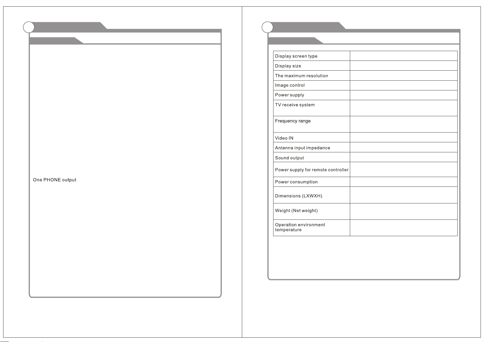
Specifications
W arnings
Color active matrix LCD display
15.6 inches diagonal (max.)
1366X768
Fine digital control
AC ~110v, 60Hz
NTSC System, ATSC System
Antenna: 2~69; Cable: 1~135 (Analog: 1-125,
Digital: 1-135)
NTSC3.58
75W (Unbalance)
2X2.5W
DC 3V (Two AAA size batteries)
38W
380 X mm150 mmX 328mm
3.4Kg
o
0C-40C
o
Note:
Design an d specificatio n modification m aybe made at any tim e without
prior not ice; all data and di mensions are app roximations.
5
6
Page 5
Accessories
General Description
Please make sure the following items are included with your LCD TV. If any items are
missing, contact your dealer.
Remote Control &
Batteries (AAAx 2)
Owner’s
Instructions
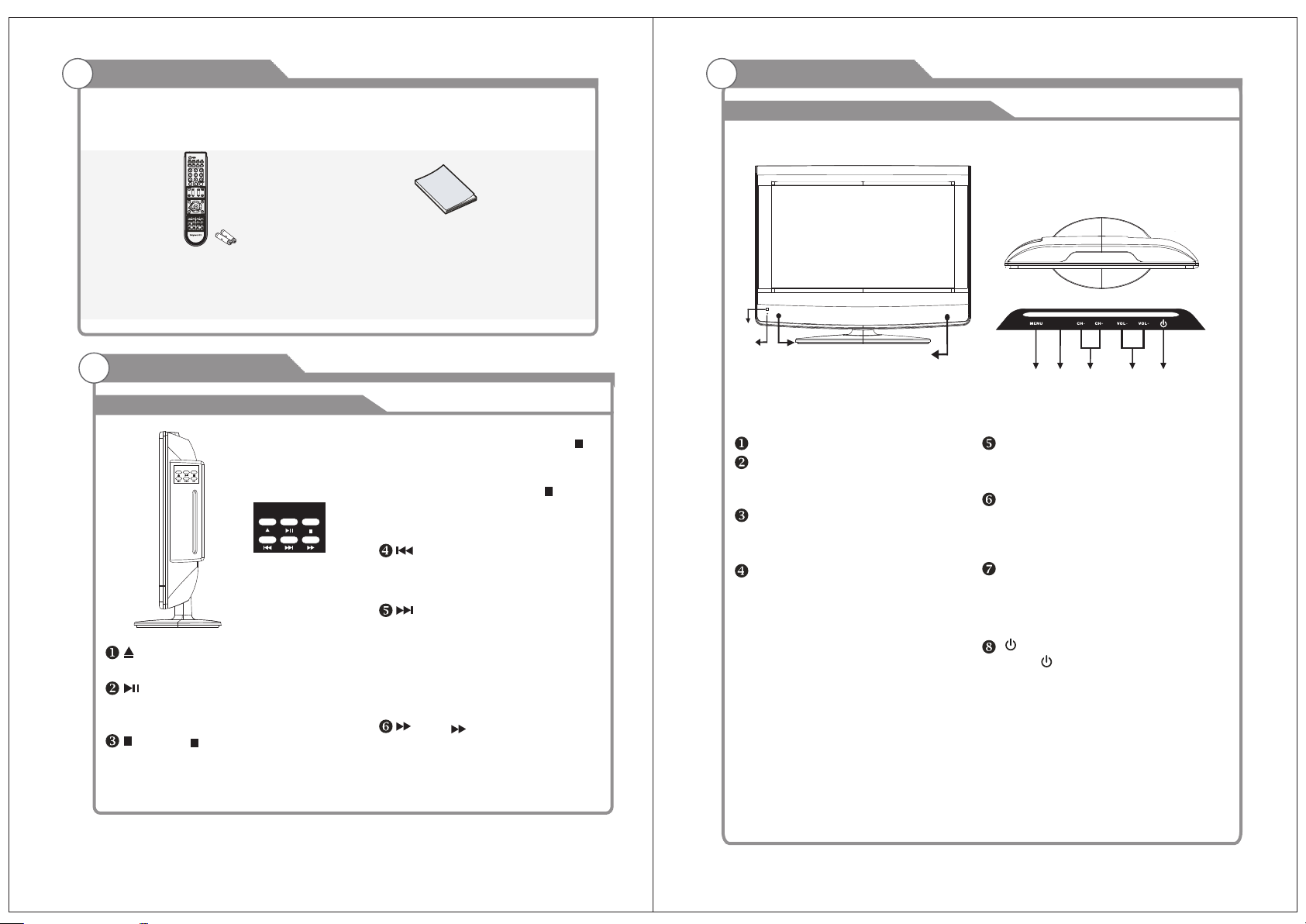
General Description
Overview of side the DVD panel
pr-essing button , press “ ”
button twice to complet-ely
stop disc,the osd shoe“stop”
and then press the“ ”button
to resume playing from the
beginni-ng of the disc
Press brtton to skip backward
DVD chapter or VCD program
or CD track
Prees button to skip advance
DVD chapter or VCD program or
Press open/closed button on the side
panel or on the remote controller
After placed a disc in the disc tray,
press button to play the disc,and
press button twice to pause
Press“ ” button to stop in two modes:
press the button once,STOP memorize
the interrupt position and the OSD
shows“pre-stop” resume play by
CD track Note:plyer will not skip
forward or backward during
“WARNING” section of a DVD
disc, single chapter DVD or
single track CD cannot skip
Press button fast forward
through the disc, repe-atedly
pressing the button, the player will
fast forw-ard playing as following
Overview of front and side panel
②
③
①
SPEAKER
REMOTE CONTROL SENSOR
Aim the remote control towards this
spot on the TV.
POWER INDICATOR
Green: In power on mode.
Red: In standby mode.
INPUT
Toggles between all the available input
sources ( TV,AV,COMPONENT,HDMI,
VGA)
①
INPUT
⑤ ④ ⑥ ⑦ ⑧
MENU
Press to see an on-screen menu of your
TV's features.
CH+/ Press to change channels.
In the on-screen menu, use the CHr/s
buttons as up/down arrow buttons.
VOL+/ Press to increase or decrease the volume.
In the on-screen menu, use the VOLv/w
buttons as left/right arrow buttons.
Standby button
Press button to toggle between normal
and standby mode.
7
8
Page 6
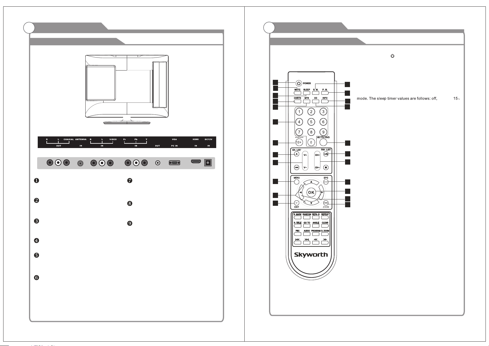
General Description
General Description
Overview of back panel
HDMI
Connect to the HDMI jack of a device
with an HDMI output.
VGA/PC IN
Connect to the video output jack on
your PC.
PC AUDIO IN
Audio input for external devices.
COMPONENT
Connect Component video.
COMPOSITE VIDEO
Video input for external devices, such
as a camcorder or VCR.
COMPOSITE COMPONENT AUDIO
Audio inputs for external devices.
PHON E
AUDIO OUT
Connect to the audio output jacks
on your amplifier/home theater.
COAXIAL
Connect to a Digital Audio devices.
ANT
Connect to an antenna or cable TV
system.
Overview of remote control
1
2
3
6
7
10
11
13
14
17
19
22
TV M ODE:
1.POWER Butto n( )
Press this button to tu rn the TV on or into standby mode.
2.MUTE Button
Press this button to mu te the sound and the sign of mute
will appear all the whil e if you do not press again.
But the sign of mute will dis appear if the CCD is display ed.
3.SLEEP Button
4
Press this button to se t the sleep timer. When the pre set
5
length of time has pass ed, the TV set enters standb y
9
8
12
16
15
18
21
20
23
45、3 0、
60、90、 120、180、240 minutes.
4.S.M. Button
Press this button to se lect desired sound mod e. Four
sound modes are avai lable including Sta ndard, Music,
Movie and Persona l.
5.P.M. Button
Press this button to se lect desired pictur e mode. Four
picture modes are av ailable includin g Standard, Soft,
Dynamic and Perso nal.
6.CHRTN Button
Press this button to wa tch the previously vie wed
channel for both ATV an d DTV.
7.MTS Button
When stereo progr am is received, press thi s button to
switch sound syst em between mono and ster eo. When
SAP program is receiv ed, press this button to swi tch
sound system betw een mono and SAP. When stere o
and SAP program is rece ived, press this butto n to switch
among mono, stere o and SAP.
8.CC Button
Press this button to se lect the CC Mode. Three CC Mode
are available inc luding On, CC on Mute and off.
9.INFO Button
Press this button to di splay the informati on on current
input.
10.NUMBER (0-9 )Buttons
Press these butto ns to enter digits. These bu ttons for
direct access to use a cha nnel to enter cha nnel number
for both ATV and DTV or enter pa ssword for V-C hip.
11.--/--- Button
In TV mode, pres s this but ton and input the channel
number whic h you want to select .
12.AV/TV/DVD But ton
Press this button to display th e input so urce such as
DTV, TV,AV, S-Video, DVD, YUV, HDMIa nd PC. Usi ng
UP/DOWN but ton select item and press RIGHT or
ENTER butto n to enter selected item.
13 CH. LIST Butt on
Press this button to display th e channel list in TV mo de.
14.VOLUME+/VOLUME- (V +/V-) Butt ons
Press these buttons to increase or decrease th e volume.
5、
10、
9
10
Page 7

General Description
General Description
Overview of remote control
15.CHANNEL+/CHANNEL- (CH+/ CH-) buttons
Press these buttons to select channe ls in asce nding
or des cendi ng order.
16.FAVORITE LIST (FAV. LIS T) Button
Press this button to display th e favorite prog ram list
17.MENU But ton
Press this button to enter the menu mode for various
optional ad justa ble settings or quit from current menu.
18.ELECTRONIC PR OGRAM GUIDE (EPG) Bu tton
Press this button to call up the Electron ic Program Guid e.
19.UP/DOWN ( ▲ / ) Buttons
Press these buttons to select the desired item s in the
menu.
20.LIFT/RIGHT ( / ) Buttons
Press these buttons to select the desired item s in the
menu, or enter the selected.
21.OK Butto n
Press this button to enter the selected item.
22.EXIT But ton
Press this button to escape fro m the curr ent operation.
23.ZOOM But ton
Press this button to select the screen si ze, such as Wide,
Zoom, Cinem a and Norm al.
Remark: If a universa l rem ote t o be us ed to c ont rol
this TV, pl eas e program the universa l rem ote w ith
Philips code.,
DVD Mode:
EJECT BUTTON( )
Press OPEN/CLOSE button to load disc on disc tray.
Hold the disc without touching either of its surfaces,
position it with the printed title side facing up, align it
with the guides, and place it in its proper position.
In case of interactive DVDs with playback control, a menu
appears on the TV screen.
PBC BUTTON
Press this button can return to the menu of the disc,
then play the disc from the first track.
AUDIO BUTTON
When play DVD, to press this button, you can change the
audio language from the one selected at the initial
settings to a different language, if available.
When play VCD, press this button consecutively and the
audio output will change as following:
LEFT MONO
▲
▲
▲
RIGHT MONO
MIX MONO
STEREO
REPEAT BUTTON(REP)
To press this button you can repeatedly play a chapter
(DVD) when " chapter " appears on TV screen ,You
can repeatedly play a title(DVD) when " title " appears
on TV screen ,You can also repeatedly play the whole
disc(DVD) when " All" appears on TV screen, and You
can cancel repeat function when no " " on TV screen.
A-B REPEAT BUTTON( A-B )
You can repeatedly play a given portion by operating as
following:
To press this button once to define the portion head.
To press this button again to define the portion toe.
Then the portion will be played repeatedly.To press this
button again to return to normal playback.
REP
RANDOM BUTTON(DVD only)
Random mode allows you to play tracks randomly by
pressing this button, pressing again will cancel
random playback.
S.TITLE BUTTON
To press this button, you can change the subtitle
language from the one selected at the initial settings
to a different language, if available.
B.MARK BUTTON:
When playing DVD disc, press this key to mark the
place where you want to replay again.
BOOK MARK
Press Enter key to mark /play;
Press clear key to clean.
You can use“ ” keys to select different content
to mark /play.
NUMERIC BUTTONS(0-9):
You can select desired titles(DVD) by pressing these
buttons directly only if the title or track number is less
than 10.
If the title or track number is over 10. For instance,
if "28" is wanted, press "10+" twice, and then press
the 2-digit number "8".
Overview of remote control
OSD BUTTON
Press this button once to show main playback in
formation on TV screen and press it again to show
playback time. Press this button at the fifth time, and
then the display will be cancelled.
DVD MENU BUTTON
If playing some DVD discs, press this button back to
root menu screen .
If playing DVDs you can use the functions of MENU,
PROGRAM and RANDOM.
OK BUTTON:
Press this button to confirm your selecting.
PROGRAM(PROG) BUTTON:
When you want to play only partial tracks/chapters of a
disc(DVDs) or to arrange the tracks/chapters playback
order, you need to program the following:
Press PROGRAM button. Then "PROGRAM" will appear
on TV screen.
Press the track number in the order you want. For example,
if the track numbers you want to
play are 1, 3 and 8, just input in the order of 1-3-8.
You can press CLEAR button to cancel and input again if
you miss input track numbers.
Now you can press " " and "OK" button to select
"START"option and enjoy the desired
tracks.
GO TO BUTTON
Press this button to go to desired position. The player
provides 3 search mode.
TITLE XX/XX CHAPTER [ ]/XXX
[DVD only]
CHAP TER XX/ XX TIME
[DVD only]
TRACK GOTO
[DVD only]
DISC GOTO
[CD]
T: XX
[CD]
When the above items are showed on LCD screen, you
can input numbers to locate desired sector, then press
PLAY to commence play.
The number you input is invalid if it is beyond the track's
capacity.
PLAY AND PAUSE BUTTON( )
Press this button to start playback. Press this button
again to pause playback.
STOP BUTTON( )
When this button is pressed once, the unit records the
stopped point, from where playback will resume
(resume function) if PLAY is pressed afterwards.
But if STOP button is pressed again instead of PLAY
button, there will be no resume function.
CLEAR BUTTON
Press this button, you can cancel the numbers you input,
just like a eraser.
SF BUTTON:
Press this button , you can play the disc slow Forward.
PREV/NEXT BUTTON( / )
Press these buttons to go to t he previous/next
chapter ( DVD ) When playing CD disc , press“ ”
button twice to select previous song.
FR/FF BUTTON( / )
These buttons allow skipping ahead/back at 5-level
speeds. Press PLAY button to return t o normal playback.
SETUP BUTTON
Press this button to get the setup menu. you can select
the setting as you like.
ANGLE BU TTO N
Some DVD c ont ain s several scen es ta ken a t the
same tim e in di ffe rent angles. P res s thi s key to
select a d iff ere nt angle (if the d isc s upp orts this
functi on. )
D.ZOOM BUTTON
Press this but ton during normal, zoom in or zoom
out playback mode. This player can magnify a
picture at 3 levels. Press this button to magnify
picture and use direction buttons to select
desired part of the zoomed picture.
“ ”
11
12
Page 8

SLEEP
P.MODE
S.MODE
LIST
1 2
3
SOURCE
+-./
ABC DEF
DTV
General Description
External Connection
Installing Batteries in the Remote Control
Installing BatteriesInstalling Batteries
Open the battery compartment
1
cover on the back side.
Insert two 1.5V AAA size batteries in
correct polarity. Don´t mix old or used
2
batteries with new ones.
Closed the cover.
3
Battery
Cover
2xsize AAA 1.5V
Battery
Cover
Point the remote towards the remote
control sensor of the wireless TV and
use it within 7 meters.
Put the used batteries into the recycling bin since it can negatively affect
the environment.
Connecting VCR
These instructions assume that you have already connected your TV to an antenna or a
cable TV system. Skip step 1 if you have not yet connected to an antenna or a cable
system.
TV Rear Panel
VCR Rear Panel
5
Audio Cable (Not supplied)
Video Cable (Not supplied)
4
RF Cable (Not supplied)
3
Follow the instructions in Viewing a VCR or Camcorder Tape to view your VCR tape.
Each VCR has a different back panel configuration.
When connecting a VCR, match the color of the connection terminal to the cable.
We recommend the use of cables with a Ferrite Core.
PHONE
Universal Remote Control operation please refer to Appendix 2.
1. Unplug the cable or antenna from the back of the TV.
2. Connect the cable or antenna to the ANT IN terminal on the back of the VCR.
External Connection
3. Connect an RF Cable between the ANT OUT terminal on the VCR and the ANT IN
terminal on the TV.
Antenna connection
4. Connect a Video Cable between the VIDEO OUT jack on the VCR and the VIDEO IN
jack on the TV.
Antenna input impedance of this unit is 75ohm. VHF/UHF 75ohm coaxial cable can be
connected to the antenna jack directly, if the antenna cable is 300ohm parallel flat feeder
cable, you need to use the 300ohm/75ohm converter to connect the antenna cable to the
antenna jack. For details Please refer to the following drawing.
Antennas with 300 W flat twins Leads
Use a 75ohm - 300ohm converter
ANT IN
300ohm coaxial cable
Antenna feeder
13
Antennas with 75 W Round Leads
75ohm coaxial cable
Antenna cable
5. Connect Audio Cables between the AUDIO OUT jacks on the VCR and the AUDIO L and
AUDIO R jacks on the TV.
If you have a mono (non-stereo) VCR, use a Y-connector (not supplied) to hook up to
the right and left audio input jacks of the TV. If your VCR is stereo, you must connect
two cables.
14
Page 9

External Connection
External Connection
Connecting DVD Player/Set-Top Box
The rear panel jacks on your TV make it easy to connect a DVD to your TV.
TV Rear Panel
DVD Player/Set-Top Box
Audio Cable (Not supplied)
2
1
Component Cable (Not supplied)
Component video separates the video into Y (Luminance (brightness)), Pb (Blue) and Pr
(Red) for enhanced video quality.
Be sure to match the component video and audio connections.
For example, if connecting the video cable to COMPONENT IN, connect the audio
cable to COMPONENT IN also.
Each DVD player/STB has a different back panel configuration.
When connecting a DVD player/STB, match the color of the connection terminal to the
cable.
We recommend the use of cables with a Ferrite Core.
1. Connect a Component Cable between the COMPONENT IN [Y, PB, PR] jacks on
the TV and the COMPONENT [Y, PB, PR] jacks on the DVD player.
2. Connect Audio Cables between the COMPONENT IN [RAUDIO-L] jacks on the TV
and the AUDIO OUT jacks on the DVD player.
PHONE
Connecting DVD Player/Set-Top Box via HDMI
This connection can only be made if there is a HDMI Output connector on the external
device.
TV Rear Panel
DVD Player/Set-Top Box
PHONE
HDMI Cable (Not supplied)
What is HDMI?
HDMI, or high-definition multimedia interface, is a next-generation interface that enables
the transmission of digital audio and video signals using a single cable without
compression.
Multimedia interface is a more accurate name for it especially because it allows multiple
channels of digital audio (5.1 channels).
The difference between HDMI and DVI is that the HDMI device is smaller in size, has the
HDCP(High Bandwidth Digital Copy Protection) coding feature installed, and supports
multi-channel digital audio.
Each DVD player/STB has a different back panel configuration.
We recommend the use of cables with a Ferrite Core.
1. Connect an HDMI Cable between the HDMI connector on the TV and the
HDMI connector on the DVD player/Set-Top Box.
15 16
Page 10

External Connection
External Connection
Connecting Digital Audio System
The rear panel jacks on your TV make it easy to connect a Digital Audio System to your TV.
Digital Audio System
COAXIAL Cable (Not supplied)
TV Rear Panel
PHONE
5.1 CH audio is possible when the TV is connected to an external device supporting 5.1
CH.
We recommend the use of cables with a Ferrite Core.
1. Connect an COAXIAL Cable between the SPDIF jacks on the TV and the Digital Audio Input
jacks on the Digital Audio System. When a Digital Audio System is connected to the
SPDIF terminal: Decrease the gain (volume) of the TV, and adjust the volume level with
the system's volume control.
Connecting Amplifier/DVD Home Theater
Amplifier/DVD Home Theater
Audio Cable (Not supplied)
Each external input source device has a different back panel configuration.
When connecting an external device, match the color of the connection terminal to the
cable.
We recommend the use of cables with a Ferrite Core.
1. Connect Audio Cables between the AUDIO L and R OUT on the TV and AUDIO IN [R AUDIO-L]on the Amplifier/DVD Home Theater.
When an audio amplifier is connected to the AV OUT [R-AUDIO-L] terminals: Decrease
the gain (volume) of the TV, and adjust the volume level with the Amplifier's volume control.
TV Rear Panel
PHONE
Connecting PC
PC
2 Pho ne Out
1
D-Sub Cable (Not supplied)
Each PC has a different back panel configuration.
The HDMI jacks do not support PC connection.
We recommend the use of cables with a Ferrite Core.
1. Connect a D-Sub Cable between RGB/PC IN connector on the TV and the PC output
connector on your computer.
2.Plu g PHONE out co nne ctor into PH ONE out jack o n the TV the TV spe aker will
be mute d.
TV Rear Panel
PHONE
Supporting signals
Input
Air
Cable
CVBS
Input
PC/VGA
PC/HDMI
Mode
8VSB
Free 64/256QAM
NTSC 3.58
Resolution
VGA
640x480
SVGA
800X600
1366X768
XGA
Input
Component
HDMI
Vertical Frequency
60Hz
60Hz
60Hz
Resolution
480i
480p
720p
1080i
1080p
480p
720p
1080i
1080p
Vertical Frequency
60Hz
60Hz
60Hz
60Hz
60Hz
60Hz
60Hz
60Hz
60Hz
17
18
Page 11

Basic Operation
Basic Operation
Turning the TV On and Off
How to turn the TV on or off
1
1. Insert the power cord plug into a polarized AC
outlet.
2. Press POWER button on the remote control or
button on the LCD TV.
3. Normal picture will be displayed on the screen after
6 seconds. If no signal input, "No Signal" will be
displayed on the screen.
4. If temporary POWER off is required, press POWER button on the remote control or
button on the LCD TV.
5. If you want to completely switch off the power for this unit, unplug the power cord plug
for this unit.
6. After switching off the unit, you should turn on the TV again at least 5 seconds later.
Status indication lamp
Green: In power on mode.
Red: In standby mode.
Auto power-off
If there is no signal input in any Mode, the TV will automatically accesses the standby
state in about 15 minutes.
Memory before turning TV off
The settings of picture and the preset channels will be memorized at turning off the unit.
When being started up again, the unit will work according to the mode set before being
turned off.
To use Car cord
Use the Car Cord provided for operation on 12V DC.
NOTE:
1.AC/ DC adaptor provided can be connected to
voltage (AC 110 volts 60HZ).
2.If the polarized AC cord does not fit into a non
attempt to file or cut
the blade. It is the user s responsibility
an electrician replace the obsolete outlet.
3.If you cause a static discharge when touching
unit fails to function, simply
minutes, and plug it back in. The unit should
a few
unplug the unit from
operation.
the specified
polarized AC outlet, do not
to have
the unit, and the
the AC outlet, wait
return to normal
NC
Menu operation
Input Setup
1
Press AV/TV/DVD key on the remote control to enter "INPUT
SOURCE" menu. There are five options for you to select: "DTV",
"TV", "DVD", "AV", "Component","HDMI",and "VGA”.
DVD
Use ▲/qkey to move the cursor to the input you desired and
press OK key to confirm.
Channels Selection
2
There are four ways to select channel:
1) Using 0~9, and OK keys on the remote control to select channel directly.
2). Using CHr/s key on the remote control or on your TV to select channel.
3) Press PRE.CH key to turn to previous channel, press it again to return to current
channel.
Note: PRE.CH is not activated if no channel has been changed after TV turning on.
4) Select channels from "All Channels List" or "Favorite Channels List".
Volume Adjustment and Mute Setup
3
Volume adjustment
Press VOLv/w key on the remote control or on the TV to display "Volume" menu,
adjust the volume of TV between 0 to 100 by using VOLv/w key:
( To increase the volume, press VOL w key;
( To decrease the volume, press VOLv key;
Mute
Press MUTE key on the remote control to display mute icon on the
left bottom of the screen, and the volume of TV will be turned off, press
MUTE key again to turn on the volume. Mute can be canceled by using
one of the methods below:
( Mute will be canceled if you press MUTE button again.
( Mute will be canceled if you press VOL w key.
Co mpo nen t
HD MI
VGA
TV
AV
19
20
Page 12

Basic Operation
Menu system instruction
Menu operation
Current Channel Information
4
Press INFO key on the remote control to display the following OSD, the indications of
items in this OSD are listed in the following table.
EPG Menu
5
Press EPG key to enter "EPG" menu, the first line displays current channel number
channel name, event title and current time.
The second line displays all programs which will be displayed in this channel, press
t/u key to select the program you desired, then press OK key to enter this program
to watch.
Picture
Picture
Press MENU key to display the main menu on the
screen, use t/u key to select "Picture" option,
then press OK or q key to enter "Picture"
submenu.
1. Picture mode
In "Picture" submenu, use p/q key to move the
cursor to "Picture Mode" option to set the mode
of video picture. Use t/u key to select one
picture mode from four modes: "Standard",
"Dynamic”, "Soft" and "Personal".
2. Contrast
In "Picture" submenu, use ▲/▼ key to move the cursor to "Contrast" option, then
press t/u key to adjust the value.
3. Brightness
In "Picture" submenu, use ▲/▼ key to move the cursor to "Brightness" option, then
press t/u key to adjust the value.
4. Color
In "Picture" submenu, use ▲/▼ key to move the cursor to "Color" option, then
press t/u key to adjust the value.
5. Tint
In "Picture" submenu, use ▲/▼ key to move the cursor to "Tint" option, then
press t/u key to adjust the value.
6. Sharpness
In "Picture" submenu, use ▲/▼ key to move the cursor to "Sharpness" option, then
press t/u key to adjust the value.
7. Color Mode
In "Picture" submenu, use ▲/▼ key to move the cursor to "Color Mode" option, then
press t/u key to select one color mode from:"Normal", "Warm", "Cool".
21
22
Page 13

Menu system instruction
Menu system instruction
Sound
Sound
Press MENU key to display the main menu on the
screen, use t/u key to select "Sound" option, then
press OK or ▼ key to enter "Sound" submenu.
1. Sound Mode
In "Sound" submenu, use ▲/▼ key to move the
cursor to the "Sound Mode" option, then use
t/u key to select one mode from following five
modes: "Standard", "Music", "Movie”
and "Personal".
2. Bass
In "Sound" submenu, use ▲/▼ key to move the cursor to the "Bass" option, then use
t/u key to adjust the value.
3. Treble
In "Sound" submenu, use ▲/▼ key to move the cursor to the "Treble" option, then use
t/u key to adjust the value.
4. Balance
In "Sound" submenu, use ▲/▼ key to move the cursor to the "Balance" option, then
use t/u key to adjust the value.
5. Surround
In "Sound" submenu, use ▲/▼ key to move the cursor to the "Surround" option,
then use t/u key to select "On" or "Off".
6. AVC
In "Sound" submenu, use ▲/▼ key to move the cursor to the "AVC" option, then use
t/u key to select "On" or "Off".
7. SPDIF Type
Only when the input source is DTV , the function of SPDIF Output is available.
In "Sound" submenu, use ▲/▼ key to select "SPDIF" option. There are two modes for
you to select:"RAW" and "PCM". Use t/u key to select the mode you desired.
Channel
Channel
Press MENU key to display the main menu on
the screen, uset/u key to select "Channel"
option, then press or ▼ key to enter ENTER
"Channel" submenu.
1. Antenna
In "Channel" submenu, use ▲/▼ key to move the cursor to "Antenna" option.
There are two options for you to select:"Cable" and "Air", press t/u key to
select the Antenna type you desired.
2. Auto Scan
In "Channel" submenu, use ▲/▼ key to
select "Auto Scan", then press or u ENTER
key to enter "Auto Scan" submenu.
1) Use ▲/▼ key to select "Cable System",
If you have selected "Cable" in "Antenna",
there are four options for you to select:
"AUTO", "STD", "HRC" and "IRC". Press
t/u key to select the option you desired.
2) Then use ▲/▼ key to select "Auto to Scan", press key or u key to start ENTER
searching. If you want to stop searching, just press EXIT key.
3. Favorite
In "Channel" submenu, use ▲/▼ key to select
"Favorite", then press key to enter ENTER
"Favorite" submenu. Use ▲/▼ key to select
your favorite channels and use key to markENTER
" " and the selected channel will be listed in
Favorite List.
8. Audio Language
In "Sound" submenu, use ▲/▼ key to move the cursor to the "Audio Language" option,
there are three options for you to select: "French", "Spanish" and "English". Press t/u
key to select the language you desired.
23
24
Page 14

Menu system instruction
Menu system instruction
Channel
4. Show/Hide
In "Channel" submenu, use ▲/▼ key to select
"Show/Hide", then press key to enter OK
"Show/Hide" submenu. Press ▲/▼ key to select the channel you want to hide or
show, then use key to mark or remove " " and the selected channel will be hiden OK
or shown.
5. Channel No.
In "Channel" submenu, use ▲/▼ key to select "Channel No.", then press t/u key to
adjust current channel, you can see the current channel number.
6. Channel Label
In "Channel" submenu, use ▲/▼ key to
select "Channel Label", then press to enter OK
"Channel Label" submenu. Use
t/u key to select and use ▲/▼ key to input
the character or digit you want, press key MENU
to confirm, then current channel is labeled.
Notes:
1. If the channel is audio program, an icon will be displayed in front of "Radio channel".
2. If a program has been added to "Hide" list, when you select program with CH△/
CH▽ key, this program will be directly jumped, but you can select the program by
using digital key on the remote control.
Time
Time
Press key to display the main menu on theMENU
screen, use t/u key to select "Time" option, then
press or ▼ key to enter "Time" submenu. OK
1. Sleep Timer
In "Time" submenu, use ▲/▼ key to move the
cursor to "Sleep Timer" option. There are eleven
options for you to select: "Off", "5 Min", "10 Min",
"15 Min", "30 Min", "45 Min", "60 Min", "90 Min",
"120 Min", "180 Min" and "240 Min", press t/u key to select "Sleep Time" you desired.
2. Time Zone
In "Time" submenu, use ▲/q key to move the cursor to "Time Zone" option. There
are six options for you to select: "Eastern", "Central", "Mountain", "Alaska",
"Pacific", "Hawaii". Press t/u key to select "Time Zone"
your desired.
3. Daylight Saving time
In "Time" submenu, use ▲/q key to move the cursor to "Daylight Saving Time" option.
You can press t/u key to select "On" or "Off".
4. Clock
Show the update time.
Setup
Setup
Press key to display the main menu on theENTER
screen, use t/u key to select "Setup" option, then
press or ▼ key to enter "Setup" submenu. OK
1. Menu Language
In "Setup" submenu, use ▲/q key to move the
cursor to select "Menu Language" option, there
are "English", and options "Français" “Español"
you can select. Press t/u key to select the
option you desired.
25
26
Page 15

Menu system instruction
Menu system instruction
Setup
2. Transparency
In "Setup" submenu, use ▲/q key to move the cursor to select "Transparency" option,
there are "On" or "Off" options you can select. Press t/u key to select the option you
desired.
3. Zoom Mode
In "Setup" submenu, use ▲/q key to move the cursor to select "Zoom Mode" option,
there are four options for you to select: "Zoom", "Cinema" and "Normal"."Wide",
Press t/u key to select zoom mode you desired.
No te :
In the VG A mode, yo u can o nly choose “N ormal” and “Wide”.
In the mo de of “Compon ent”a nd “HDMI”, you ca n only
choos e the “Wide”, “Cinema”a nd “Zoom”.
4. Noise Reduction
In "Setup" submenu, use ▲/q key to move the cursor to "Noise Reduction" option,
there are four options for you to select: "Off", "Weak", "Middle" and "Strong". Press
t/u key to select noise reduction you desired.
5. Advance
In "setup” submenu, use ▲/▼ key to move
the cursor to the "Advance" option, then use
t/u key to adjust the related value.
This function is only available for VGA.
1) H-POS
In "Advance” submenu, use ▲/q key to move the
cursor to the "H-POS” option, then press t/u key
2) V-POS
In "Advance” submenu, use ▲/q key to move the
then presst/u key
3) CLOCK
In "Advance” submenu, use ▲/q key to move the
then presst/u key
4) PHASE
In "Advance” submenu, use ▲/q key to move the
then presst/u key
5) AUTO
In "Advance” submenu, use ▲/q key to move the
then press u key this option will auto adjust the H-POS,V-POS,CLOCK and
PHASE of the VGA picture.
to adjust the value.
to adjust the value.
to adjust the value.
to adjust the value.
cursor to the “ ” option, V-POS
cursor to the “ ” option, CLOCK
cursor to the “ ” option, PHASE
cursor to the “ ” option, AUTO
Setup
6. Closed caption
In "Setup" submenu, use ▲/q key to move the
cursor to "Closed Caption" option, then press
or u key to enter "Closed Caption" submenu.then press ENTER
1) CC Mode
In "Setup" submenu, use ▲/q key to move
the cursor to "CC Mode" option, you can press
t/u key to select "On", "CC on mute" or "Off".
2) Basic Selection
In "Closed Caption" submenu, use ▲/q key to
move the cursor to "Basic Selection" option,
there are eight options for you to select: "CC1",
"CC2", "CC3", "CC4", "TEXT1", "TEXT2",
"TEXT3" and "TEXT4". Press t/u key to select services mode you desired.
3) Advanced Selection
In "Closed Caption" submenu, use ▲/q key to move the cursor to "Advanced
Selection" option, there are six options for you to select: "Servcice 1", "Servcice 2",
"Servcice 3", "Servcice 4", "Service 5" and "Service 6". Press t/u key to select
advanced mode you desired.
4) Option
In "Closed Caption" submenu, use ▲/q key to move the cursor to "Option", then
press or u key to enter "Option".OK
i) Mode
In "Option" submenu, use ▲/q key to move
the cursor to "Mode" option. You can press
t/u key to select "Custom" or "Default".
ii) Only when the "Mode" is "Custom", you can
press t/u key to move the cursor to "Font
Style", "Font Size", "Font Edge Style", "Font
Edge Color", "FG Color", "BG Color", "FG
Opacity", "BG Opacity", then use t/u key
to set them. Settings you can select is
27
28
Page 16

Menu system instruction
Menu system instruction
Setup
shown below:
Font Style : Default, Font0, Font1, Font2, Font3, Font4, Font5, Font6, Font7
Font Size : Default, normal, Large, Small
Font Edge Style: Default, None, Raised, Pepressed, Uniform, Left shadow, Right
shadow
Font Edge Color: Default, Black, White, Red, Green, Blue, Yellow, Magenta, Cyan
FG Color: Default, White, Black, Red, Green, Blue, Yellow, Magenta, Cyan
BG Color: Default, Black, White, Red, Green, Blue, Yellow, Magenta, Cyan
FG Opacity : Default, Solid, Flashing, Translucent, transparent
BG Opacity : Default,Solid,Flashing,Translucent,transparent
7. DLC(Dynamic Luminance Control)
In "Setup" submenu, use ▲/q key to move the cursor to select "DLC" option, then
press t or u key to select "On" or "Off".
8. Restore Default
In "Setup" submenu, use ▲/q key to move the cursor to select "Restore Default"
option, then press or u key to enter "Restore Default" submenu. Use t/u key to OK
select "Yes" or "No", then press “ ” to confirm. If you select "Yes", all settings will be OK
restored default settings.
Lock
Lock
1. Change Password
In “Lock” submenu, use ▲/▼ key to move the
cursor to select "Change Password" option,
then press 0-9 digital keys to enter "Change
Password" submenu. Use digital keys on the
remote to change the password. Only when
you input the same password twice, the
password is set successfully.
2. Rating Enable
In "Lock" submenu, use ▲/▼ key to move the
cursor to select “ ” option, then Rating Enable
use key to select "On" or "Off".t/u
Note: Only when the “ ” is "On", Rating Enable
you can use ▲/▼ key to move the
cursor to "US", "Canada" and "Reset
RRT".
Press MENU key to display the main menu on
the screen,use t/u key to select “Lock” option,
then press OK or u key to enter “Enter
Password”, input the password to enter “Lock”
submenu (the default and universal password
is 0000) .
29
3. US
In “Lock” submenu, use ▲/▼ key to move the
cursor to select "US" option, then press or ENTER
key to enter u "US" submenu.
30
Page 17

Menu system instruction
Lock
1) TV
In "US" submenu, use ▲/▼ key to move the cursor to select "TV" option, then
press or key to enter ENTER u
option you desired. Press key to lock the option.ENTER
2) MPAA
In "US" submenu, use ▲/▼ key to move the cursor to select
are seven options for you to select
press key to select the option you desired. t/u
4. Canada
In "Lock" submenu, use ▲/▼ key to move the cursor to select "Canada " option, then
press or key to enter ENTER u "Canada " submenu.
1) Canada English
In "Canada" submenu, use ▲/▼key to move the cursor to select "Canada
option. There are seven options for you to select: "C", "C8+", "G", "PG", "14+",
"18+" and "E". Press key to select the option you desired. t/u
2) Canada French
In "Canada" submenu, use ▲/▼ key to move the cursor to select "Canada
option. There are six options for you to select: "E", "G", "8ans+", "13ans+",
"16ans+" and "18ans+". Press key to select the option you desired.t/u
5. Reset RRT
In "Lock" submenu, use key to move the cursor to select▲/▼ "Reset RRT " option,
then press or OK u key to enter "Reset RRT "submenu. Use key to select "Yes" t/u
or "No", then press “ ” to confirm. If you select "Yes", all RRT settings will be OK
restored default settings.
"TV" submenu. Use▲/▼and key to select the t/u
" option. There
"MPAA
: "R", "NC-17", "X", "N/A", "G", "PG
"and"PG-13",
English
French
DVD OPERATION
Basic Operation
1. Turn On the TV and then press "AV/TV/DVD " button of the remote cont roller,
switch into DVDthe TV will mode.
2. Place a disc ho rizontally into the dis c slot, it will then be autom atically loaded into
the mechanism.
NOTE: Another di sc can not be loaded i f there is already o ne in mechan ism.
b. No disc in mechanism, i t will be initialized whe n the power turns on (autom atically
loads in about 7 secon ds).
c. When it ejects, th e disc will be automatica lly reload af ter about 10 seconds lat er if
not removed.
d. Compatible wit h both 12CM d isc.
a) Menu Play (compatible wi th DVD, SVCD, VCD2.0 dis cs)
I. Stop
1) When you press the Stop button for the f irst time, the player to pr e-stop mode.
2) In pre-stop mo de , the player remembers where you have stoppe d, when you start
"
"
playing the disc again, the DVD player wi ll pick up where y ou stopped.
b) Title Play (comp atible with DVD discs only ).
I. During DVD playb ack, p ress the Title button t o display the DVD title contents .
c) programme Play (com patible with DVD, SVCD, VCD, CD, HD-CD, JPEG discs)
The programme Playb ack option allows you to enter the o rder in which you want
chapters or track s to be played, a maxi mum of 16.
INITAL SETTING (DVD)
Setup Menu
31
32
Page 18

DVD remote control
1.
TV
2.
3.
4.
CLOSE D
5.
6.
Troubleshooting
MUTE
8
TV TYPE:Ac cording to t he CO LOR Type of the TV,y ou can choos e the TV Type
1.
accor ding to your TV.
NOTE: AUTO type is reco mme nded.
2.
3.
4.
DEFAULT: Back to the factory setting.
33
34
Page 19

Picture defects and the reason
35
Page 20

For Sales Information Please Contact
RoadTrucker Inc (www.RoadTrucker.com)
8312 Sidbury Rd. Wilmington, NC 28411
(800) 507-0482 / (910) 686-4281
MSD119
 Loading...