

Page 1

USER’S MANUAL
USER’S MANUAL
13"LCD HDTV/DVD COMBO
SLC-1369A-3
Page 2
1
IMPORTANT SAFETY INSTRUCTIONS
1. Read these instructions.
2. Keep these instructions.
3. Heed all warnings.
4. Follow all instructions.
5. Do not use this apparatus near water.
6. Clean only with dry cloth.
7. Do not block any ventilation openings. Install in accordance with the
manufacturer's instructions.
8. Do not install near any heat sources such as radiators, heat registers, stoves,
or other apparatus (including amplifiers) that produce heat.
9. Do not defeat the safety purpose of the polarized or grounding-type plug. A
polarized plug has two blades with one wider than the other. A grounding type
plug has two blades and a third grounding prong. The wide blade or the third
prong is provided for your safety. If the provided plug does not fit into your
outlet, consult an electrician for replacement of the obsolete outlet.
10. Protect the power cord from being walked on or pinched particularly at plugs,
convenience receptacles, and the point where they exit from the apparatus.
11. Only use attachments/accessories specified by the manufacturer.
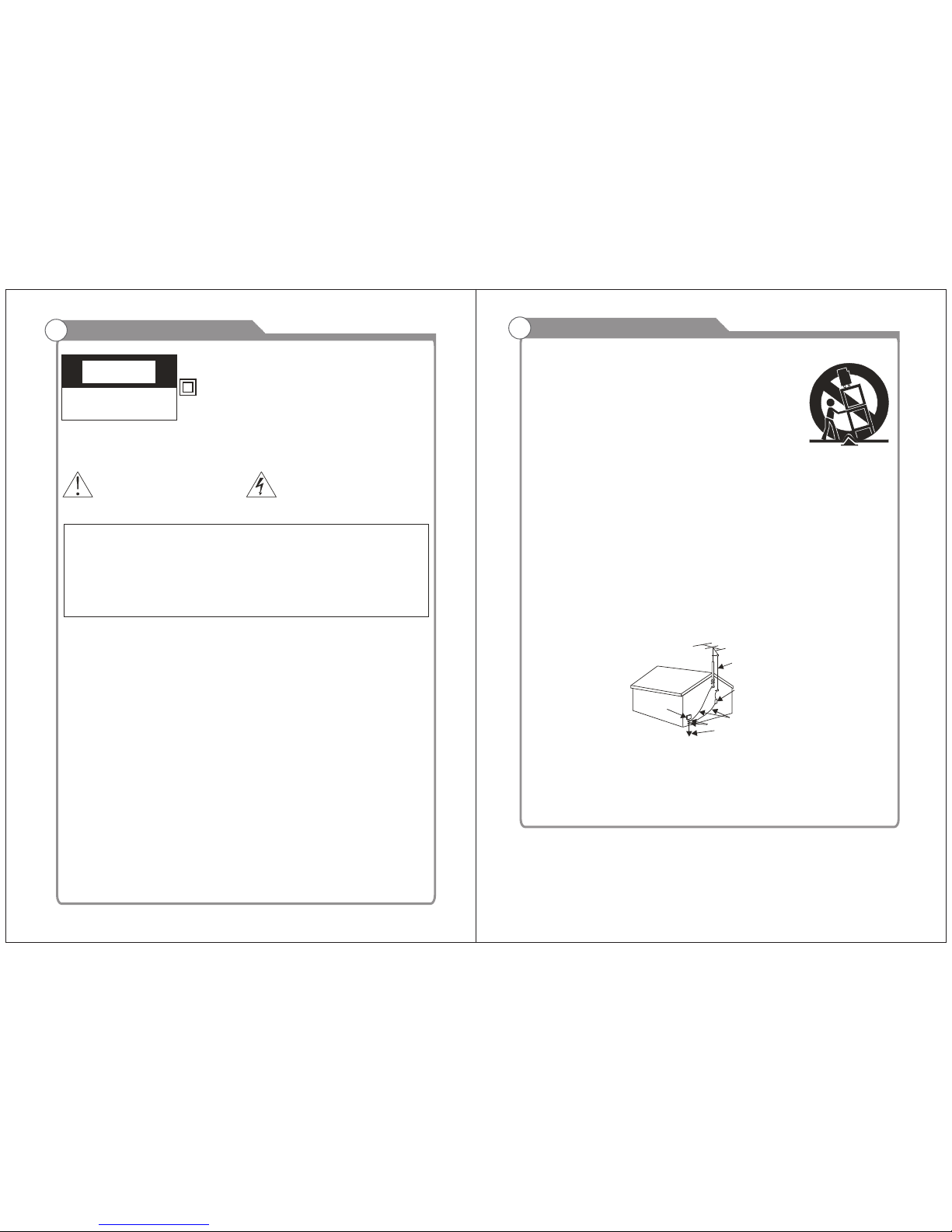
CAUTION
RISK OF ELECTRIC SHOCK
DO NOT OPEN
This symbol indicates that this product incorporates
double insulation between hazardous mains voltage
and user accessible parts.
When servicing use only identical replacement parts.
This symbol indicates important
instructions accompanying the
product.
WARNING
To reduce the risk of fire or electric shock, do not expose this product to rain or
moisture.
The apparatus must not be exposed to dripping or splashing. Objects filled with
liquids, such as vases or drinking glasses, must never be placed on the
apparatus.
This symbol indicates "dangerous
voltage" inside the product that
presents a risk of electric shock
or personal injury.
Caution: To reduce the risk of electric shock, do not remove cover (or back). No
user serviceable parts inside. Refer servicing to qualified service personnel.
Important Safety Precautions
2
12. Use only with the cart, stand, tripod, bracket, or table
specified by the manufacturer, or sold with the apparatus.
When a cart is used, use caution when moving the cart/
apparatus combination to avoid injury from tip-over.
13. Unplug this apparatus during lightning storms or when
unused for long periods of time.
14. Refer all servicing to qualified service personnel.
Servicing is required when the apparatus has been damaged in any way, such
as power-supply cord or plug is damaged, liquid has been spilled or objects
have fallen into the apparatus, the apparatus has been exposed to rain or
moisture, does not operate normally, or has been dropped.
15. If an outside antenna or cable system is connected to the product, be sure the
antenna or cable system is grounded so as to provide some protection
against voltage surges and built-up static charges. Section 810 of the National
Electrical Code, ANSI/NFPA No. 70-1984 (Section 54 of Canadian Electrical
Code, Part 1) provides information with respect to proper grounding of the
mast and supporting structure, grounding of the lead-in wire to an antenna-
discharge unit, size of grounding conductors, location of antenna-discharge
unit, connection to grounding electrode. See following example.
16. Mains plug is used as the disconnect device. It shall remain readily operable
and should not be obstructed during intended use.
This apparatus shall be connected to a mains socket outlet with a protective
earthing connection.
ELECTRIC
SERVICE
EQUIPMENT
NEC-NATIONAL ELECTRICALCODE
POWER SERVICE GROUNDING
ELECTRODE SYSTEM
(NEC ART 250 PART H)
GROUND CLAMPS
GROUNDING CONDUCTORS
(NEC SECTION 810-21)
ANTENNA
DISCHARGE UNINT
(NEC SECTION 810-21)
ANTENNA
LEAD IN
WIRE
Important Safety Precautions
Page 3
3
Table of Contents
4
Table of Contents
Time
Setup
Troubleshooting
26
26
32
30
Introduction
Features
Specifications
5
6
Accessories
General Description
Overview of front and side panel
Overview of back panel
Overview of remote control
Installing Batteries in the Remote Control
7
7
8
9
10
13
External Connection
Antenna connection
Connecting VCR
Connecting DVD Player/Set-Top Box
Connecting DVD Player/Set-Top Box via HDMI
Connnecting Digital Audio System
Connecting Amplifier/DVD Home Theater
Connecting PC
14
15
16
17
17
18
13
13
Menu system introduction
Picture
Sound
Channel
22
22
23
24
Input Setup
Supporting signals
Basic operation
Turning the TV On and Off
Channels Selection
Volume Adjustment and Mute Setup
EPG Menu
18
19
19
20
20
20
21
DVD Part-BASIC OPERATION
Lock
28
Current Channel in formation
21
Page 4
5
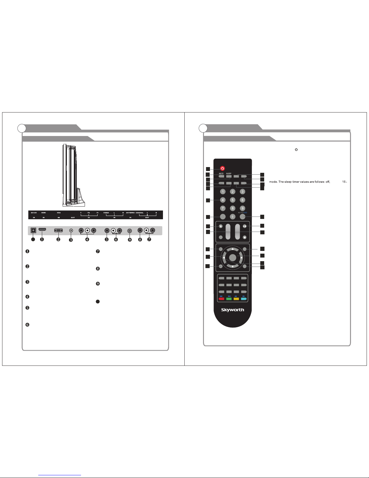
Input terminals used for external equipment connection
One ANTENNA jack
One computer VGA/PC input One outputCOAXIAL
One COMPONENT inputs One HDMI inputs
One AV inputs One AUDIO output
l TV adopts 13" LCD display screen
l HDTV Compatible( 480p,720p, 1080i, 1080p)
l Support American TV Standard 8VSB/Free 64/256QAM,NTSC System, ATSC System
l Connect to computer directly to realize TV/monitor combo.
l Zero X radiation complies to green environment protection requirement
l Advanced Chroma Processing
l Closed captioning/PARENTAL LOCK
l SAP/STEREO/MONO; BTSC.
l HDMI inputs
l Support COAXIAL ouput
W arnings
Features
Introduction
6
Note:
Introduction
W arnings
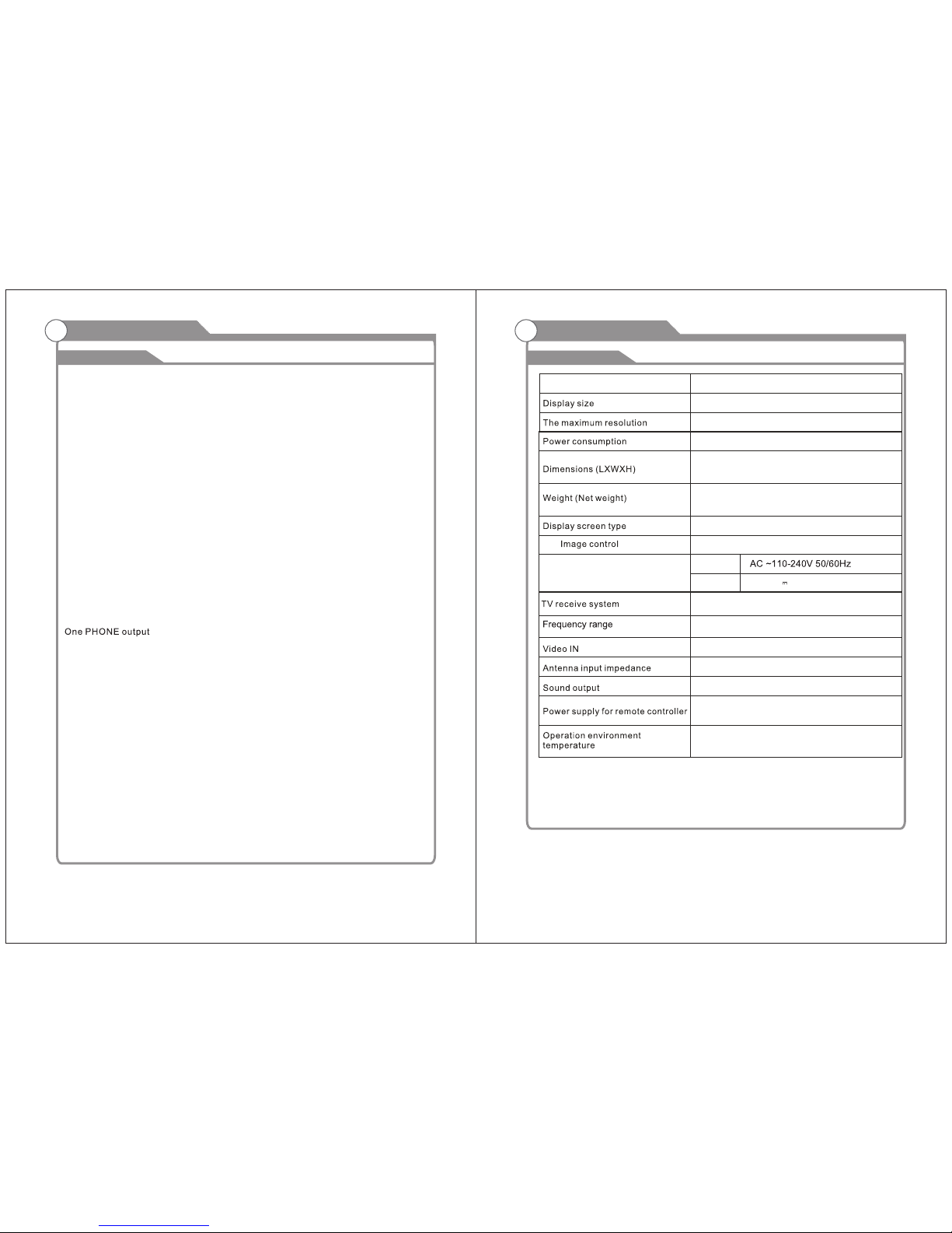
Specifications
Design and specification modification maybe made at any time without
prior notice; all data and dimensions are approximations.
mm
Fine digital control
NTSC3.58
75 (Unbalance)
5W x 2
25W
1280X800
SLC-1369A-3
Color active matrix LCD display
350mm X116mmX380mm
2.1Kg
NTSC System, ATSC System
Antenna: 2~69; Cable: 1~135 (Analog: 1-125,
Digital: 1-135)
DC 3V (Two AAA size batteries)
o
0C-40C
o
IN Put
Out Put
Ada pter re quire ment
DC 12V 3A:
MOD EL
13”
(Max)
Page 5
7
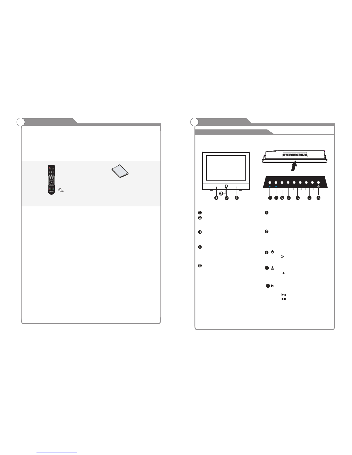
Remote Control &
Batteries (AAAx 2)
Please make sure the following items are included with your LCD TV. If any items are
missing, contact your dealer.
Owner’s
Instructions
Accessories
8
SPEAKER
REMOTE CONTROL SENSOR
Aim the remote control towards this
spot on the TV.
POWER INDICATOR
Green: In power on mode.
Red: In standby mode.
INPUT
Toggles between all the available input
sources ( TV,AV, DVD,COMPONENT,
HDMI, VGA)
MENU
Press to see an on-screen menu of your
TV's features.
CH+/ Press to change channels.
In the on-screen menu, use the CH +/ buttons as up/down arrow buttons.
VOL+/ Press to increase or decrease the volume.
In the on-screen menu, use the VOL +/ buttons as left/right arrow buttons.
Standby button
Press button to toggle between normal
and standby mode.
General Description
Overview of front and side panel
Press button on the side
panel or
After placed a disc in the disc tray,
press button to play the disc,and
press button twice to pause.
SOUND PICTURE
RECALL
DISPLAY
EJECT PAUSE/PLAY
OSD STOP
STEUP
SF
DVD MENU
B.MARKRANDOM
REPA-B
REPEAT
S.TITLE
GO TO
ANGLE CLEAR
PBC AUDIO
PROGRAM
D.ZOOM
ENTER
CH
+
CH
-
V+
V+
POWER
CH.LIST FAV.LIST
EPG
MENU
ZOOM
EXIT
/
---
MTS CC
HDMTV
VOL- VOL+CH- C H+
MENU I NPUT
/
9 1 0
on the remote controller.
9
10
Page 6
9
HDMI
Connect to the HDMI jack of a device
with an HDMI output.
VGA/PC IN
Connect to the video output jack on
your PC.
PHONE OUT
Connect a set of phone for private
COMPONENT
Connect Component video.
COMPOSITE VIDEO
Video input for external devices, such
as a camcorder or VCR.
General Description
Overview of back panel
COMPOSITE COMPONENT AUDIO
Audio inputs for external devices.
AUDIO OUT
Connect to the audio output jacks
on your amplifier/home theater.
COAXIAL
Connect to a Digital Audio devices.
ANT
Connect to an antenna or cable TV
system.
10
Overview of remote control
General Description
11."-/--, ." Button
In TV mode, press this button and input the channel
number which you want to select.
12.AV/TV/DVD Button
Press this button to display the input source such as
"TV”, "AV”, " ”, "Component" ,"HDMI" and "VGA"DVD
13. CH. LIST Button
Press this button to display the channel list in TV mode.
14.VOLUME+/VOLUME- (V+/V-) Buttons
Press these buttons to increase or decrease the volume.
TV MODE:
1.POWER Button( )
Press this button to turn the TV on or into standby mode.
2.MUTE Button
Press this button to mute the sound and the sign of mute
will appear all the while if you do not press again.
But the sign of mute will disappear if the CCD is displayed.
3.SLEEP Button
Press this button to set the sleep timer. When the preset
length of time has passed, the TV set enters standby
60、90 、 120、180 、240 minutes.
4.SOUND Button
Press this button to select desired sound mode. Four
sound modes are available including Standard, Music,
Movie and Personal.
5.PICTURE Button
Press this button to select desired picture mode. Four
picture modes are available including Standard, Soft,
Dynamic and Personal.
6.RECALL Button
This button is used to return to the previous channel
7.MTS Button
W hen stereo program is received, press this button to
switch sound system between mono and stereo. When
SAP program is received, press this button to switch
sound system between mono and SAP. When stereo
and SAP program is received, press this button to switch
among mono, stereo and SAP.
8.CC Button
9. ButtonDISPLAY
Press this button to display the information on current
input.
10.NUMBER (0-9)Buttons
Press these buttons to enter digits. These buttons for
direct access to use a channel to enter channel number
for both ATV and DTV or enter password for Parental lock.
1
3
6
10
11
5
9
4
8
2
7
12
16
18
23
22
13
14
15
17
19
20
21
5、
10、
45、30、
PHONE
10
listening
DC12V IN
Connect the supplied power
UP/DOWN button select item and press
Using
ENTER button to enter selected item.
or
RIGHT
This button doesn’t Look in this model
SOUND
PICTURE
RECALL
DISPLAY
EJECT
PAUSE/PLAY
OSD STOP
STEUP
SF
DVD MENU
B.MARK
RANDOM
REPA-B
REPEAT
S.TITLE
GO TO
ANGLE CLEAR
PBC
AUDIO
PROGRAM
D.ZOOM
ENTER
CH
+
CH
-
V+
V+
POWER
CH.LIST FAV.LIST
EPG
MENU
ZOOM
EXIT
/
-- -
MTS
CC
HDTV
.
10
Page 7

( / )
( / )
Page 8

SLEEP
P.MODE
S.MODE
LIST
1 2
3
SOURCE
+-./
ABC DEF
DTV
13
Installing Batteries in the Remote Control
Installing BatteriesInstalling Batteries
1
Open the battery compartment
cover on the back side.
2
Insert two 1.5V AAA size batteries in
correct polarity. Don´t mix old or used
batteries with new ones.
3
Closed the cover.
Point the remote towards the remote
control sensor of the wireless TV and
use it within 7 meters.
Put the used batteries into the recycling bin since it can negatively affect
the environment.
Universal Remote Control operation please refer to Appendix 2.
General Description
Battery
Cover
2xsize AAA 1.5V
Battery
Cover
Antenna connection
Antenna input impedance of this unit is 75ohm. VHF/UHF 75ohm coaxial cable can be
connected to the antenna jack directly, if the antenna cable is 300ohm parallel flat feeder
cable, you need to use the 300ohm/75ohm converter to connect the antenna cable to the
antenna jack. For details Please refer to the following drawing.
Use a 75ohm - 300ohm converter
300ohm coaxial cable
Antenna feeder
ANT IN
75ohm coaxial cable
Antenna cable
Antennas with 300 W flat twins Leads
Antennas with 75 W Round Leads
External Connection
External Connection
Connecting VCR
14
These instructions assume that you have already connected your TV to an antenna or a
cable TV system. Skip step 1 if you have not yet connected to an antenna or a cable
system.
5
VCR Rear Panel
4
3
Audio Cable (Not supplied)
Video Cable (Not supplied)
RF Cable (Not supplied)
Follow the instructions in Viewing a VCR or Camcorder Tape to view your VCR tape.
Each VCR has a different back panel configuration.
When connecting a VCR, match the color of the connection terminal to the cable.
We recommend the use of cables with a Ferrite Core.
1. Unplug the cable or antenna from the back of the TV.
2. Connect the cable or antenna to the ANT IN terminal on the back of the VCR.
3. Connect an RF Cable between the ANT OUT terminal on the VCR and the ANT IN
terminal on the TV.
4. Connect a Video Cable between the VIDEO OUT jack on the VCR and the VIDEO IN
jack on the TV.
5. Connect Audio Cables between the AUDIO OUT jacks on the VCR and the AUDIO L and
AUDIO R jacks on the TV.
If you have a mono (non-stereo) VCR, use a Y-connector (not supplied) to hook up to
the right and left audio input jacks of the TV. If your VCR is stereo, you must connect
two cables.
TV Rear Panel
PHONE
The batteries shall not be eposed to ecessive heat such as sunshine
fire of the like.
Page 9

and the AUDIO OUT jacks on the DVD player.
the TV and the COMPONENT [Y, PB, PR] jacks on the DVD player.
External Connection
Connecting DVD Player/Set-Top Box via HDMI
This connection can only be made if there is a HDMI Output connector on the external
device.
What is HDMI?
HDMI, or high-definition multimedia interface, is a next-generation interface that enables
the transmission of digital audio and video signals using a single cable without
compression.
Multimedia interface is a more accurate name for it especially because it allows multiple
channels of digital audio (5.1 channels).
The difference between HDMI and DVI is that the HDMI device is smaller in size, has the
HDCP(High Bandwidth Digital Copy Protection) coding feature installed, and supports
multi-channel digital audio.
Each DVD player/STB has a different back panel configuration.
We recommend the use of cables with a Ferrite Core.
1. Connect an HDMI Cable between the HDMI connector on the TV and the
HDMI connector on the DVD player/Set-Top Box.
TV Rear Panel
HDMI Cable (Not supplied)
DVD Player/Set-Top Box
Connecting DVD Player/Set-Top Box
The rear panel jacks on your TV make it easy to connect a DVD to your TV.
Component video separates the video into Y (Luminance (brightness)), Pb (Blue) and Pr
(Red) for enhanced video quality.
Be sure to match the component video and audio connections.
For example, if connecting the video cable to COMPONENT IN, connect the audio
cable to COMPONENT IN also.
Each DVD player/STB has a different back panel configuration.
When connecting a DVD player/STB, match the color of the connection terminal to the
cable.
We recommend the use of cables with a Ferrite Core.
1. Connect a Component Cable between the COMPONENT IN [Y, PB, PR] jacks on
2. Connect Audio Cables between the COMPONENT IN [RAUDIO-L] jacks on the TV
TV Rear Panel
Audio Cable (Not supplied)
2
Component Cable (Not supplied)
1
DVD Player/Set-Top Box
15 16
External Connection
PHONE
PHONE
Page 10

External Connection
Connecting Digital Audio System
The rear panel jacks on your TV make it easy to connect a Digital Audio System to your TV.
5.1 CH audio is possible when the TV is connected to an external device supporting 5.1
CH.
We recommend the use of cables with a Ferrite Core.
1. Connect an COAXIAL Cable between the SPDIF jacks on the TV and the Digital Audio
jacks on the Digital Audio System. When a Digital Audio System is connected to the Input
SPDIF terminal: Decrease the gain (volume) of the TV, and adjust the volume level with
the system's volume control.
TV Rear Panel
COAXIAL Cable (Not supplied)
Digital Audio System
Connecting Amplifier/DVD Home Theater
Each external input source device has a different back panel configuration.
When connecting an external device, match the color of the connection terminal to the
cable.
We recommend the use of cables with a Ferrite Core.
1. Connect Audio Cables between the AUDIO L and R OUT on the TV and AUDIO IN [R AUDIO-L]on the Amplifier/DVD Home Theater.
When an audio amplifier is connected to the AV OUT [R-AUDIO-L] terminals: Decrease
the gain (volume) of the TV, and adjust the volume level with the Amplifier's volume control.
TV Rear Panel
Audio Cable (Not supplied)
Amplifier/DVD Home Theater
Connecting PC
Each PC has a different back panel configuration.
The HDMI jacks do not support PC connection.
We recommend the use of cables with a Ferrite Core.
1. Connect a D-Sub Cable between RGB/PC IN connector on the TV and the PC output
connector on your computer.
TV Rear Panel
D-Sub Cable (Not supplied)
PC
1
External Connection
17
18
2.Plug PHONE out connector into PHONE out jack on the TV the TV speaker will
be muted.
2 Phone Out
Supporting signals
PHONE
PHONE
PHONE
102 4X768
Page 11

Menu operation
1
Input Setup
Press AV/TV/DVD key on the remote control to enter "INPUT
SOURCE" menu. There are five options for you to select:
Use ▲/qkey to move the cursor to the input you desired and
press ENTER key to confirm.
Channels Selection
There are four ways to select channel:
1) Using 0~9, and keys on the remote control to select channel directly.ENTER
2). Using CHr/s key on the remote control or on your TV to select channel.
3) Press PRE.CH key to turn to previous channel, press it again to return to current
channel.
Note: PRE.CH is not activated if no channel has been changed after TV turning on.
4) Select channels from "All Channels List" or "Favorite Channels List".
Volume Adjustment and Mute Setup
Volume adjustment
Press VOL +/- key on the remote control or on the TV to display "Volume" menu,
adjust the volume of TV between 0 to 100 by using VOL key:+/-
( To increase the volume, press VOL + key;
( To decrease the volume, press VOL - key;
Mute
Press MUTE key on the remote control to display mute icon on the
left bottom of the screen, and the volume of TV will be turned off, press
MUTE key again to turn on the volume. Mute can be canceled by using
one of the methods below:
( Mute will be canceled if you press MUTE button again.
( Mute will be canceled if you press VOL + key.
2
Basic Operation
3
19
20
Turning the TV On and Off
1. Insert the power cord plug into a polarized AC
outlet.
2. Press POWER button on the remote control or
button on the LCD TV.
3. Normal picture will be displayed on the screen after
6 seconds. If no signal input, "No Signal" will be
displayed on the screen.
4. If temporary POWER off is required, press POWER button on the remote control or
button on the LCD TV.
5. If you want to completely switch off the power for this unit, unplug the power cord plug
for this unit.
6. After switching off the unit, you should turn on the TV again at least 5 seconds later.
Status indication lamp
Green: In power on mode.
Red: In standby mode.
Auto power -off
If there is no signal input in any Mode, the TV will automatically accesses the standby
state in about 15 minutes.
Memory before turning TV off
The settings of picture and the preset channels will be memorized at turning off the unit.
When being started up again, the unit will work according to the mode set before being
turned off.
1
How to turn the TV on or off
Basic Operation
"TV", "DVD", "AV", "Component","HDMI",and "VGA”.
AV
Component
DVD
To use Car cord
Use the Car Cord provided for operation on 12V DC.
polarized AC outlet, do not
the blade. It is the user s responsibility
to have
an electrician replace the obsolete outlet.
3.If you cause a static discharge when touching
the unit, and the
unit fails to function, simply
unplug the unit from
the AC outlet, wait
a few
minutes, and plug it back in. The unit should
return to normal
NOTE:
1.AC/ DC adaptor provided can be connected to
the specified
2.If the polarized AC cord does not fit into a non
NC
voltage (AC 110 volts 60HZ).
attempt to file or cut
operation.
TV
HDMI
VGA
Page 12

Menu operation
Basic Operation
Current Channel Information
Press INFO key on the remote control to display the following OSD, the indications of
items in this OSD are listed in the following table.
EPG Menu
Press EPG key to enter "EPG" menu, the first line displays current channel number
channel name, event title and current time.
The second line displays all programs which will be displayed in this channel, press
t/u key to select the program you desired, then press key to enter this program ENTER
to watch.
4
5
Picture
Press MENU key to display the main menu on the
screen, use key to select "Picture" option, t/u
then press or q key to enter "Picture" ENTER
submenu.
1. Picture mode
In "Picture" submenu, use key to move the ▲/▼
cursor to "Picture Mode" option to set the mode
of video picture. Use key to select one t/u
picture mode from four modes: "Standard",
"Dynamic”, "Soft" and "Personal".
2. Contrast
In "Picture" submenu, use ▲/▼ key to move the cursor to "Contrast" option, then
press t/u key to adjust the value.
3. Brightness
In "Picture" submenu, use ▲/▼ key to move the cursor to "Brightness" option, then
press t/u key to adjust the value.
6. Sharpness
In "Picture" submenu, use ▲/▼ key to move the cursor to "Sharpness" option, then
press t/u key to adjust the value.
5. Tint
In "Picture" submenu, use ▲/▼ key to move the cursor to "Tint" option, then
press t/u key to adjust the value.
4. Color
In "Picture" submenu, use ▲/▼ key to move the cursor to "Color" option, then
press t/u key to adjust the value.
7. Color Mode
In "Picture" submenu, use ▲/▼ key to move the cursor to "Color Mode" option, then
press t/u key to select one color mode from:"Normal", "Warm", "Cool".
Picture
Menu system instruction
21
22
Page 13

Sound
Press MENU key to display the main menu on the
screen, use t/u key to select "Sound" option, then
press ENTER or ▼ key to enter "Sound" submenu.
1. Sound Mode
In "Sound" submenu, use ▲/▼ key to move the
cursor to the "Sound Mode" option, then use
t/u key to select one mode from following four
modes: "Standard", "Music", "Movie”
and "Personal".
2. Bass
In "Sound" submenu, use ▲/▼ key to move the cursor to the "Bass" option, then use
t/u key to adjust the value.
3. Treble
In "Sound" submenu, use ▲/▼ key to move the cursor to the "Treble" option, then use
t/u key to adjust the value.
4. Balance
In "Sound" submenu, use ▲/▼ key to move the cursor to the "Balance" option, then
use t/u key to adjust the value.
5. Surround
In "Sound" submenu, use ▲/▼ key to move the cursor to the "Surround" option,
then use t/u key to select "On" or "Off".
6. AVC
In "Sound" submenu, use ▲/▼ key to move the cursor to the "AVC" option, then use
t/u key to select "On" or "Off".
7. SPDIF Type
Only when the input source is DTV , the function of SPDIF Output is available.
In "Sound" submenu, use ▲/▼ key to select "SPDIF" option. There are two modes for
you to select:"RAW" and "PCM". Use t/u key to select the mode you desired.
8. Audio Language
In "Sound" submenu, use ▲/▼ key to move the cursor to the "Audio Language" option,
there are three options for you to select: "French", "Spanish" and "English". Press t/u
key to select the language you desired.
Sound
Menu system instruction
Channel
Channel
Press MENU key to display the main menu on
the screen, uset/u key to select "Channel"
option, then press or ▼ key to enter ENTER
"Channel" submenu.
1. Antenna
In "Channel" submenu, use ▲/▼ key to move the cursor to "Antenna" option.
There are two options for you to select:"Cable" and "Air", press t/u key to
select the Antenna type you desired.
2. Auto Scan
In "Channel" submenu, use ▲/▼ key to
select "Auto Scan", then press or u ENTER
key to enter "Auto Scan" submenu.
1) Use ▲/▼ key to select "Cable System",
If you have selected "Cable" in "Antenna",
there are four options for you to select:
"AUTO", "STD", "HRC" and "IRC". Press
t/u key to select the option you desired.
2) Then use ▲/▼ key to select "Auto to Scan", press key or u key to start ENTER
searching. If you want to stop searching, just press EXIT key.
4. Favorite
In "Channel" submenu, use ▲/▼ key to select
"Favorite", then press key to enter ENTER
"Favorite" submenu. Use ▲/▼ key to select
your favorite channels and use key toENTER
” " and the selected channel will be listed in mark
Favorite List.
Menu system instruction
23
24
3. Auto Scan add CH
In "Channel" submenu, use ▲/▼ key to
select “ ”, then press Auto Scan add CH or u ENTER
key to enter “ ” submenu.Auto Scan add CH
Page 14

5. Show/Hide
In "Channel" submenu, use ▲/▼ key to select
"Show/Hide", then press key to enter ENTER
"Show/Hide" submenu. Press ▲/▼ key to select the channel you want to hide or
show, then use key to mark or remove " " and the selected channel will be hiden ENTER
or shown.
6. Channel No.
In "Channel" submenu, use ▲/▼ key to select "Channel No.", then press t/u key to
adjust current channel, you can see the current channel number.
7. Channel Label
In "Channel" submenu, use ▲/▼ key to
select "Channel Label", then press to enter ENTER
"Channel Label" submenu. Use
t/u key to select and use ▲/▼ key to input
the character or digit you want, press key MENU
to confirm, then current channel is labeled.
Notes:
1. If the channel is audio program, an icon will be displayed in front of "Radio channel".
2. If a program has been added to "Hide" list, when you select program with CH△/
CH▽ key, this program will be directly jumped, but you can select the program by
using digital key on the remote control.
Channel
Menu system instruction
Time
Time
Press key to display the main menu on theMENU
screen, use t/u key to select "Time" option, then
press or ▼ key to enter "Time" submenu. ENTER
1. Sleep Timer
In "Time" submenu, use ▲/▼ key to move the
cursor to "Sleep Timer" option. There are eleven
options for you to select: "Off", "5 Min", "10 Min",
"15 Min", "30 Min", "45 Min", "60 Min", "90 Min",
"120 Min", "180 Min" and "240 Min", press t/u key to select "Sleep Time" you desired.
2. Time Zone
In "Time" submenu, use ▲/q key to move the cursor to "Time Zone" option. There
are six options for you to select: "Eastern", "Central", "Mountain", "Alaska",
"Pacific", "Hawaii". Press t/u key to select "Time Zone"
your desired.
3. Daylight Saving time
In "Time" submenu, use ▲/q key to move the cursor to "Daylight Saving Time" option.
You can press t/u key to select "On" or "Off".
4. Clock
Show the update time.
Setup
Press key to display the main menu on theMENU
screen, use t/u key to select "Setup" option, then
press or ▼ key to enter "Setup" submenu. ENTER
1. Menu Language
In "Setup" submenu, use ▲/q key to move the
cursor to select "Menu Language" option, there
are "English", and options "Français" “Español"
you can select. Press t/u key to select the
option you desired.
Setup
Menu system instruction
25
26
2. Transparency
desired.
In "Setup" submenu, use ▲/q key to move the cursor to select "Transparency" option,
there are "On" or "Off" options you can select. Press t/u key to select the option you
Page 15

Setup
3. Zoom Mode
In "Setup" submenu, use ▲/q key to move the cursor to select "Zoom Mode" option,
there are four options for you to select: "Zoom", "Cinema" and "Nor mal"."Wide",
Press t/u key to select zoom mode you desired.
4. Noise Reduction
In "Setup" submenu, use ▲/q key to move the cursor to "Noise Reduction" option,
there are four options for you to select: "Off", "Weak", "Middle" and "Strong". Press
t/u key to select noise reduction you desired.
5. Advance
In "setup” submenu, use ▲/▼ key to move
the cursor to the "Advance" option, then use
t/u key to adjust the related value.
This function is only available for VGA.
Menu system instruction
1) H-POS
In "Advance” submenu, use ▲/q key to move the
cursor to the "H-POS” option, then press t/u key
to adjust the value.
2) V-POS
In "Advance” submenu, use ▲/q key to move the
cursor to the “ ” option, V-POS
to adjust the value.
then presst/u key
3) CLOCK
In "Advance” submenu, use ▲/q key to move the
cursor to the “ ” option, CLOCK
to adjust the value.
then presst/u key
4) PHASE
In "Advance” submenu, use ▲/q key to move the
cursor to the “ ” option, PHASE
to adjust the value.
then presst/u key
5) AUTO
In "Advance” submenu, use ▲/q key to move the
cursor to the “ ” option, AUTO
then press u key this option will auto adjust the H-POS,V-POS,CLOCK and
PHASE of the VGA picture.
27
28
Note:
In the VGA mode, you can only choose “Normal” and “Wide”.
In the mode of “Component”and “HDMI”, you can only
choose the “Wide”, “Cinema”and “Zoom”.
6. DLC(Dynamic Luminance Control)
In "Setup" submenu, use ▲/q key to move the cursor to select "DLC" option, then
press t or u key to select "On" or "Off".
7. Restore Default
In "Setup" submenu, use ▲/q key to move the cursor to select "Restore Default"
option, then press or u key to enter "Restore Default" submenu. Use t/u key to ENTER
select "Yes" or "No", then press “ ” to confirm. If you select "Yes", all settings ENTER
restored default settings.will be
Lock
Press MENU key to display the main menu on
the screen, use key to select“Lock”option,
then press ENTER or u key to enter “Enter
Password”, input the password to enter “Lock”
submenu (the default and universal password
is 0000) .
Menu system instruction
1. Change Password
In “Lock” submenu, use ▲/▼ key to move the
cursor to select "Change Password" option,
then press 0-9 digital keys to enter "Change
Password" submenu. Use digital keys on the
remote to change the password. Only when
you input the same password twice, the
password is set successfully.
2. System Lock
In "Lock" submenu, use ▲/▼ key to move the
cursor to select “ ” option, then System Lock
use key to select "On" or "Off".t/u
Note: Only when the “ ” is "On", System Lock
you can use ▲/▼ key to move the
cursor to "US", "Canada" and "Reset
RRT".
3. US
In “Lock” submenu, use ▲/▼ key to move the
cursor to select "US" option, then press or ENTER
key to enter u "US" submenu.
Lock
t/u
Page 16

29
30
Lock
1) TV
In "US" submenu, use ▲/▼ key to move the cursor to select "TV" option, then
press ENTER or key to enter u
"TV" submenu. Use▲/▼and key to select the t/u
option you desired. Press key to lock the option.ENTER
2) MPAA
In "US" submenu, use ▲/▼ key to move the cursor to select
"MPAA
" option. There
are seven options for you to select
: "R", "NC-17", "X", "N/A", "G", "PG
"and"PG-13",
press key to select the option you desired. t/u
4. Canada
In "Lock" submenu, use ▲/▼ key to move the cursor to select "Canada " option, then
press or key to enter ENTER u "Canada " submenu.
1) Canada English
In "Canada" submenu, use ▲/▼key to move the cursor to select "Canada
"
option. There are seven options for you to select: "C", "C8+", "G", "PG", "14+",
"18+" and "E". Press key to select the option you desired. t/u
2) Canada French
In "Canada" submenu, use ▲/▼ key to move the cursor to select "Canada
"
option. There are six options for you to select: "E", "G", "8ans+", "13ans+",
"16ans+" and "18ans+". Press key to select the option you desired.t/u
5. Reset RRT
In "Lock" submenu, use key to move the cursor to select▲/▼ "Reset RRT " option,
then press ENTER or u key to enter "Reset RRT "submenu. Use key to select "Yes" t/u
or "No", then press “ ” to confirm. If you select "Yes", all RRT settings will be ENTER
restored default settings.
English
French
Menu system instruction
1. Turn On the TV and then press "AV/TV/DVD" button of the remote controller,
switch into DVDthe TV will mode.
2. Place a disc horizontally into the disc slot, it will then be automatically loaded into
the mechanism.
NOTE: Another disc can not be loaded if there is already one in mechanism.
b. No disc in mechanism, it will be initialized when the power turns on (automatically
loads in about 7 seconds).
c. When it ejects, the disc will be automatically reload after about 10 seconds later if
not removed.
d. Compatible with both 12CM disc.
a) Menu Play (compatible with DVD
VCD2.0 discs)
I. Stop
1) When you press the Stop button for the first time, the player to pre-stop mode.
2) In pre-stop mode , the player remembers where you have stopped, when you start
playing the disc again, the DVD player will pick up where you stopped.
b) Title Play (compatible with DVD discs only).
I. During DVD playback, press the Title button to display the DVD title contents.
c) programme Play (compatible with DVD, VCD, CD, JPEG discs)
The programme
Playback option allows you to enter the order in which you want
chapters or tracks to be played, a maximum of 16.
Basic Operation
INITAL SETTING(DVD)
Setup Menu
DVD OPERATION
Page 17

TV
CLOSED
TV TYPE:According to the COLOR Type of the TV,you can choose the TV Type
according to your TV.
NOTE:AUTO type is recommended.
1.
2.
3.
4.
5.
1.
2.
3.
4.
DEFAULT : Back to the factory setting.
DVD remote control
31
32
8
MUTE
Troubleshooting
Page 18

33
Picture defects and the reason
Page 19

MSD119
 Loading...