

Skyworks Solutions, Inc. • Phone [781] 376-3000 • Fax [781] 376-3100 • sales@skyworksinc.com • www.skyworksinc.com
200136 Rev. A • Skyworks Proprietary Information • Products and Product Information are Subject to Change Without Notice. • February 7, 2005 1
SC Series: MIS Chip Capacitors
DATA SHEET
Description
Skyworks MIS Chip Capacitors are available in a wide range of
sizes and capacitance values. They are frequently used in
applications requiring DC blocking, RF bypassing, or as a fixed
capacitance tuning element in filters, oscillators, and matching
networks. The devices have a dielectric composed of thermally
grown silicon dioxide over which a layer of silicon nitride is
deposited. This dielectric possesses a low temperature coefficient
of capacitance and very high insulation resistance. The devices
also exhibit excellent long term stability making them suitable for
high reliability applications. The capacitors have a high dielectric
breakdown which permits the use of thin dielectrics resulting in
large capacitance per unit area. The temperature coefficient is
less that 50 ppm/°C, and operation is suitable from -65 °C to
200 °C. Compared to ceramic capacitors, Skyworks MIS chip
capacitors offer higher Q, and a lower insertion loss of 0.04 dB,
in a 50 Ω accommodate high volume automated assembly
methods, wafers can be supplied on expanded film frame. To
reduce cost, chips can be supplied with only sample testing
packaged in vials. Packaging in waffle packs with 100% electrical test and visual inspection is always available if required.
Features
●
Readily available from stock
●
High reliability silicon oxide–nitride dielectric
●
Low loss — typically 0.04 dB in a 50 Ω system
●
Operation through 26 GHz
●
Wide temperature operation
Characteristic Value
Operating temperature range (TOP) -65 to +200 °C
Storage temperature range (T
STG
) -65 to +200 °C
Dielectric withstanding voltage 100 V
Absolute Maximum Ratings
Performance is guaranteed only under the conditions listed in the specifications table and is
not guaranteed under the full range(s) described by the Absolute Maximum specifications.
Exceeding any of the absolute maximum/minimum specifications may result in permanent
damage to the device and will void the warranty.
CAUTION: Although this device is designed to be as robust as
possible, Electrostatic Discharge (ESD) can damage
this device. This device must be protected at all times
from ESD. Static charges may easily produce potentials of several kilovolts on the human body or
equipment, which can discharge without detection.
Industry-standard ESD precautions must be employed
at all times.
Electrical Specifications
Capacitance range1:0.8 to 1000 pF
Temperature coefficient: 50 ppm/°C typical
Capacitance tolerance
2:
±20%
Operating temperature: -65 °C to 200 °C
Dielectric withstanding voltage: 100 V
Insulation resistance: 10
5
megohms typical
Leakage current: typ. < 1 nA
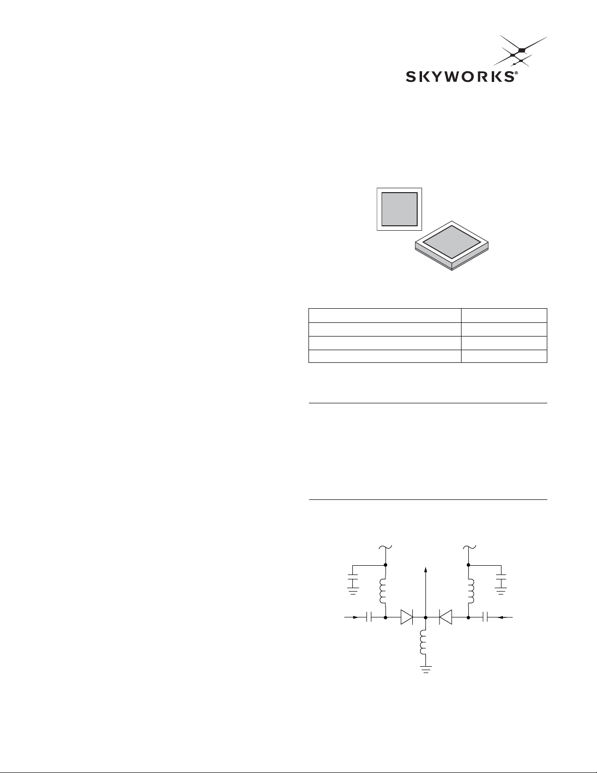
BIAS
BIAS
OUTPUT
INPUT 1 INPUT 2
C
1
D
1
D
2
C
2
C
4
C
3
Typical SPDT Switch
C2,C3— Chip MIS capacitor
C
1,C4
— Chip or beam — lead MIS capacitor
D
1,D2
DSG9500 beam — lead pIN diode
Skyworks Solutions, Inc. • Phone [781] 376-3000 • Fax [781] 376-3100 • sales@skyworksinc.com • www.skyworksinc.com
February 7, 2005 • Skyworks Proprietary Information • Products and Product Information are Subject to Change Without Notice. • 200136 Rev. A
DATA SHEET • SC SERIES
2
Electrical Specifications
Performance Data
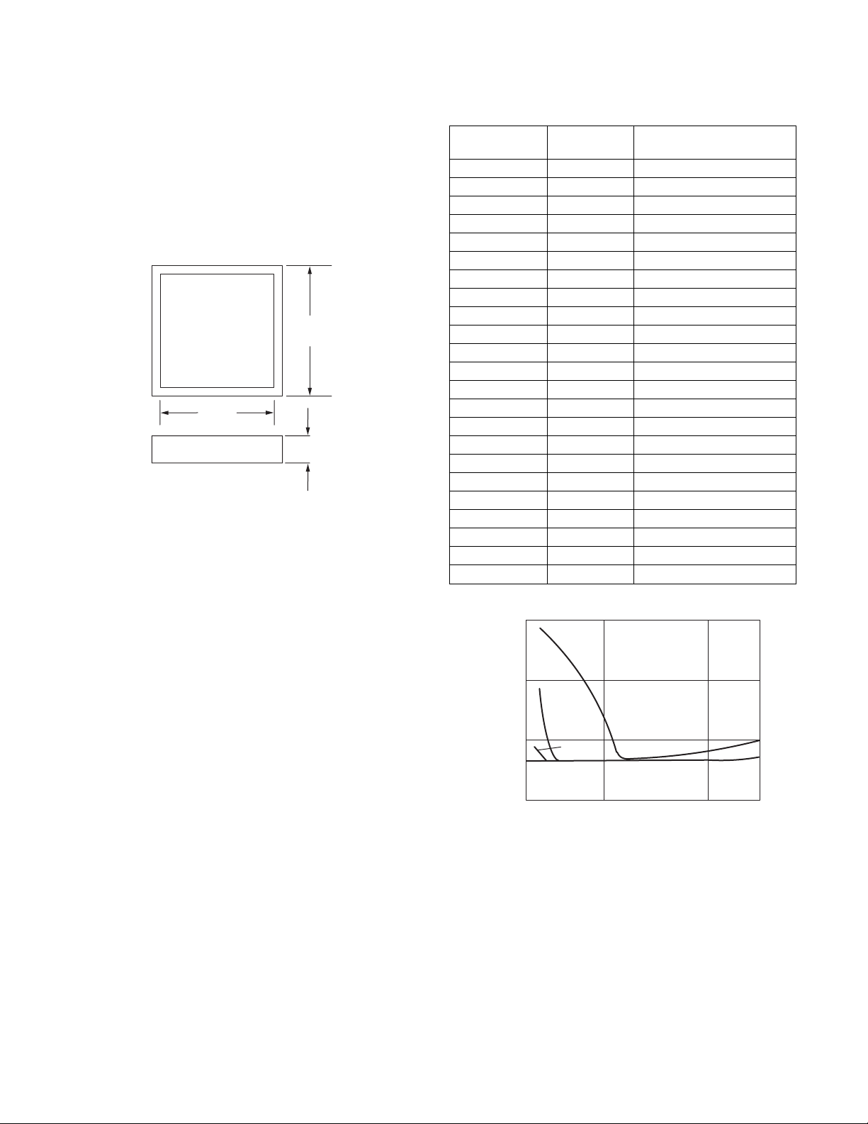
Tests on typical MIS capacitors at L and S band show insertion
loss to be 1/2 to 1/3 that of equivalent ceramic type capacitors,
without any of the associated resonance problems. Power tests
indicate that the only limitation is the actual breakdown voltage
of the device (see data section). A typical insertion loss versus
frequency graph is shown in Figure 1. This data is taken from an
actual tests circuit with series mounted beam-lead or chip
capacitors on a 50 Ω microstrip transmission line. The apparent
higher loss at lower frequencies on the lower capacitance units is
strictly due to the capacitive reactance of the capacitor.
Capacitance Chip Dimensions
Part Number (+ 20%) (+ 1 mil)
SC00080912 0.8 9 mil pad/12 mil chip
SC00120912 1.2 9 mil pad/12 mil chip
SC00180912 1.8 9 mil pad/12 mil chip
SC00260912 2.6 9 mil pad/12 mil chip
SC00380912 3.8 9 mil pad/12 mil chip
SC00560912 5.6 9 mil pad/12 mil chip
SC00680912 6.8 9 mil pad/12 mil chip
SC00820710 8.2 7 mil pad/10 mil chip
SC00821518 8.2 15 mil pad/18 mil chip
SC01000710 10 7 mil pad/10 mil chip
SC01000912 10 9 mil pad/12 mil chip
SC01001518 10 15 mil pad/18 mil chip
SC01500710 15 7 mil pad/10 mil chip
SC01500912 15 9 mil pad/12 mil chip
SC01501518 15 15 mil pad/18 mil chip
SC02201518 22 15 mil pad/18 mil chip
SC03301518 33 15 mil pad/18 mil chip
SC04701518 47 15 mil pad/18 mil chip
SC06801518 68 15 mil pad/18 mil chip
SC10002430 100 24 mil pad/30 mil chip
SC33303440 333 34 mil pad/40 mil chip
SC50004450 500 44 mil pad/50 mil chip
SC99906068 1000 60 mil pad/68 mil chip
Example
Part Number Structure — SCXXXXYYZZ
where:
SC = Silicon Capacitor
XXXX = Capacitance (pF)
YY = Square Contact Size (mils)
ZZ = Square Chip Size (mils)
ZZ
± 0.001˚
YY
± 0.001˚
Chip Thickness
0.005
± 0.001˚
10.0
1.0
0.10
Insertion Loss (dB)
1 pF
8.2 pF
47 pF
100 pF
100 pF
1–47 pF
0.01
2 6 10 14 18
Frequency (GHz)
Figure 1. Typical Insertion
Loss vs. Frequency (50 Ω System)

DATA SHEET • SC SERIES
Skyworks Solutions, Inc. • Phone [781] 376-3000 • Fax [781] 376-3100 • sales@skyworksinc.com • www.skyworksinc.com
200136 Rev. A • Skyworks Proprietary Information • Products and Product Information are Subject to Change Without Notice. • February 7, 2005 3
Copyright © 2002, 2003, 2004, 2005, Skyworks Solutions, Inc.All Rights Reserved.
Information in this document is provided in connection with Skyworks Solutions, Inc. (“Skyworks”) products.These materials are provided by Skyworks as a service to its customers and may be
used for informational purposes only by the customer. Skyworks assumes no responsibility for errors or omissions in these materials. Skyworks may make changes to its documentation, products,
specifications and product descriptions at any time, without notice. Skyworks makes no commitment to update the information and shall have no responsibility whatsoever for conflicts,
incompatibilities, or other difficulties arising from future changes to its documentation, products, specifications and product descriptions.
No license, express or implied, by estoppel or otherwise, to any intellectual property rights is granted by or under this document. Except as may be provided in Skyworks Terms and Conditions of
Sale for such products, Skyworks assumes no liability whatsoever in association with its documentation, products, specifications and product descriptions.
THESE MATERIALS ARE PROVIDED “AS IS” WITHOUT WARRANTY OF ANY KIND, EITHER EXPRESS OR IMPLIED OR OTHERWISE, RELATING TO SALE AND/OR USE OF SKYWORKS PRODUCTS INCLUDING
WARRANTIES RELATING TO FITNESS FOR A PARTICULAR PURPOSE, MERCHANTABILITY, PERFORMANCE, QUALITY OR NON-INFRINGEMENT OF ANY PATENT, COPYRIGHT OR OTHER INTELLECTUAL
PROPERTY RIGHT. SKYWORKS FURTHER DOES NOT WARRANT THE ACCURACY OR COMPLETENESS OF THE INFORMATION, TEXT, GRAPHICS OR OTHER ITEMS CONTAINED WITHIN THESE MATERIALS.
SKYWORKS SHALL NOT BE LIABLE FOR ANY DAMAGES, INCLUDING SPECIAL, INDIRECT, INCIDENTAL, OR CONSEQUENTIAL DAMAGES,INCLUDING WITHOUT LIMITATION, LOST REVENUES OR LOST
PROFITS THAT MAY RESULT FROM THE USE OF THESE MATERIALS WHETHER OR NOT THE RECIPIENT OF MATERIALS HAS BEEN ADVISED OF THE POSSIBILITY OF SUCH DAMAGE.
Skyworks products are not intended for use in medical, lifesaving or life-sustaining applications. Skyworks customers using or selling Skyworks products for use in such applications do so at their
own risk and agree to fully indemnify Skyworks for any damages resulting from such improper use or sale.
The following are trademarks of Skyworks Solutions, Inc.: Skyworks
®
, the Skyworks logo, and Breakthrough Simplicity®. Product names or services listed in this publication are for identification
purposes only, and may be trademarks of Skyworks or other third parties.Third-party brands and names are the property of their respective owners. Additional information, posted at
www.skyworksinc.com, is incorporated by reference.
 Loading...