

Page 1
INSTRUCTION MANUAL
Copyright © Sky-Watcher
SL26032014 V1
Star Discovery Mount
Page 2

CONTENT
Part I: Introduction
A simple mount, yet efficient .............................................................................................. 2
Part II: Getting Started
Parts description ................................................................................................................ 3
Installing the Star Discovery mount for an observation ....................................................... 3
Preparing the telescope for an observation ........................................................................ 5
Aligning the finder scope .................................................................................................... 7
Part III: Astronomy with the Hand Control
Initial setup ........................................................................................................................ 8
Quick Setup ....................................................................................................................... 9
Using the Hand Controller for Astronomy ..........................................................................10
Part IV: Terrestrial Photography
Installing the Mounting Bracket .........................................................................................11
General Operations ..........................................................................................................12
Setting and retrieving preset positions ..............................................................................12
Camera Cruising Function ................................................................................................13
Video Cruising and Time-Lapse Photography Function ....................................................13
Panoramic/Matrix Photography .........................................................................................14
Part V: Astronomy with the SynScan Version 4
Moving the mount around .................................................................................................16
Initial setup .......................................................................................................................17
Aligning the Star Discovery Mount ....................................................................................18
The Brightest Star Alignment Method ...............................................................................18
The 2-Star Alignment Method ...........................................................................................20
Locating Objects ...............................................................................................................21
Identifying Objects ............................................................................................................24
The SynScan Version 4 menu tree ...................................................................................25
Appendix: Tips for observing the sky
Page 3
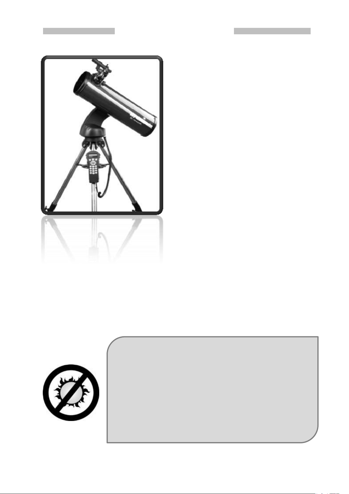
A simple mount, yet efficient
When designing the Star Discovery mount,
Sky-Watcher engineers kept these words in
mind. A simple mount that can really do
astronomy, helps beginners to discover the
night sky efficiently and will become a tool
that can fulfill your passion.
The Star Discovery mount is not only
designed to drive a telescope, but is also a
multi-role platform for cameras and video
recorders. Perfect for lightweight
astrophotography, time lapse photography,
wide view and panorama photography, video
panning and so many more activities.
With motors on both axes the Star Discovery
mount can be driven from one point to
another accurately in no time and can
pinpoint any object. Any night sky object will
be in the center of the field of view in no
time, or your camera will frame that scene
exactly as you like it.
The Star Discovery mount even includes
digital encoders and the patented “Freedom
Find TM” technology like the biggest SkyWatcher mounts. After moving to a new
object the telescope will automatically begin
to track the new object accurately. No resetup is required in one observing session.
NEVER USE YOUR TELESCOPE TO LOOK DIRECTLY AT THE
SUN. PERMANENT EYE DAMAGE WILL RESULT.
NEVER USE AN EYEPIECE-TYPE SOLAR FILTER.
NEVER USE YOUR TELESCOPE TO PROJECT SUNLIGHT ONTO
ANOTHER SURFACE; THE INTERNAL HEAT BUILD-UP WILL
DAMAGE THE TELESCOPE OPTICAL ELEMENTS.
USE A PROPER SOLAR FILTER FIRMLY MOUNTED ON THE
FRONT OF THE TELESCOPE FOR VIEWING THE SUN.
WHEN OBSERVING THE SUN, PLACE A DUST CAP OVER
YOUR FINDERSCOPE OR REMOVE IT TO PROTECT YOU
FROM ACCIDENTAL EXPOSURE.
NEVER LET A TELESCOPE POINTING THE SUN UNATTENDED.
Part I : Introduction
Part I: Introduction
If not enough the Star Discovery mount can host the SynScan Version 4, the latest SynScan
GO-TO handset. This handset can drive the Sky Discovery mount to any object selected
from its huge 42000+ object database, including objects from Messier, IC, NGC and Caldwell
catalogs, the planets, named stars, double stars, variable stars and even user-defined
objects like new comets.
Part II: Getting Started
2
Page 4
Part II: Getting Started
Star Discovery SD-Track bundle
Star Discovery SD-GoTo bundle
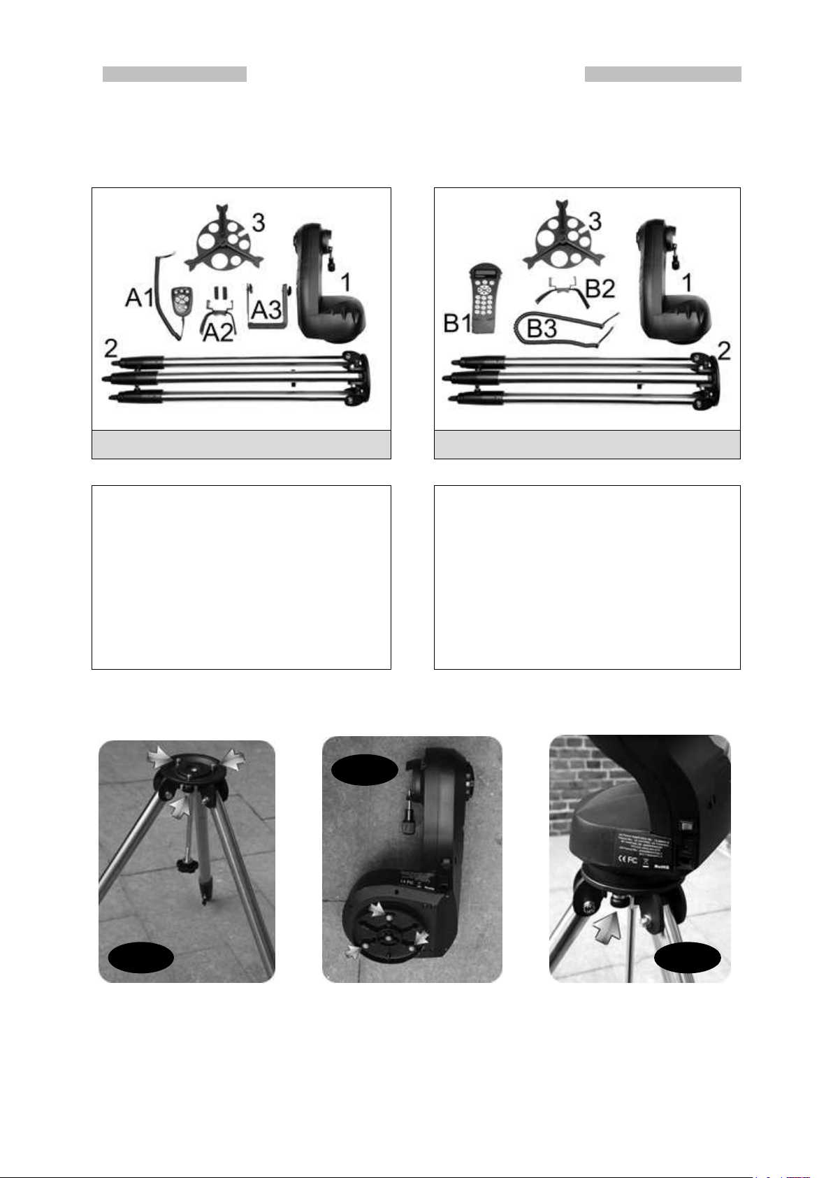
Common Parts:
1. The Star Discovery mount
2. The tripod with adjustable legs
3. The accessory tray
Specific Parts to SD-Track
A1 Hand Controller
A2 Leg support for Hand Controller
A3 Mounting bracket assembly
Common Parts:
1. The Star Discovery mount
2. The tripod with adjustable legs
3. The accessory tray
Specific Parts to SD-GoTo
B1 SynScan version 4 hand controller
B2 Leg support for SynScan
B3 Connection cable for SynScan
Fig. 1
Fig. 2
Fig. 3
Parts description
When unpacking the mount box, depending on your controller model, you will find the
following parts enclosed:
Installing the Star Discovery mount for an observation
Install the base on the observation point. Extend the legs at desired height and level the base
(Fig. 1). You don’t have to align a leg to a specific direction. Please note the three screws
position on the base.
3
Page 5
Part II: Getting Started
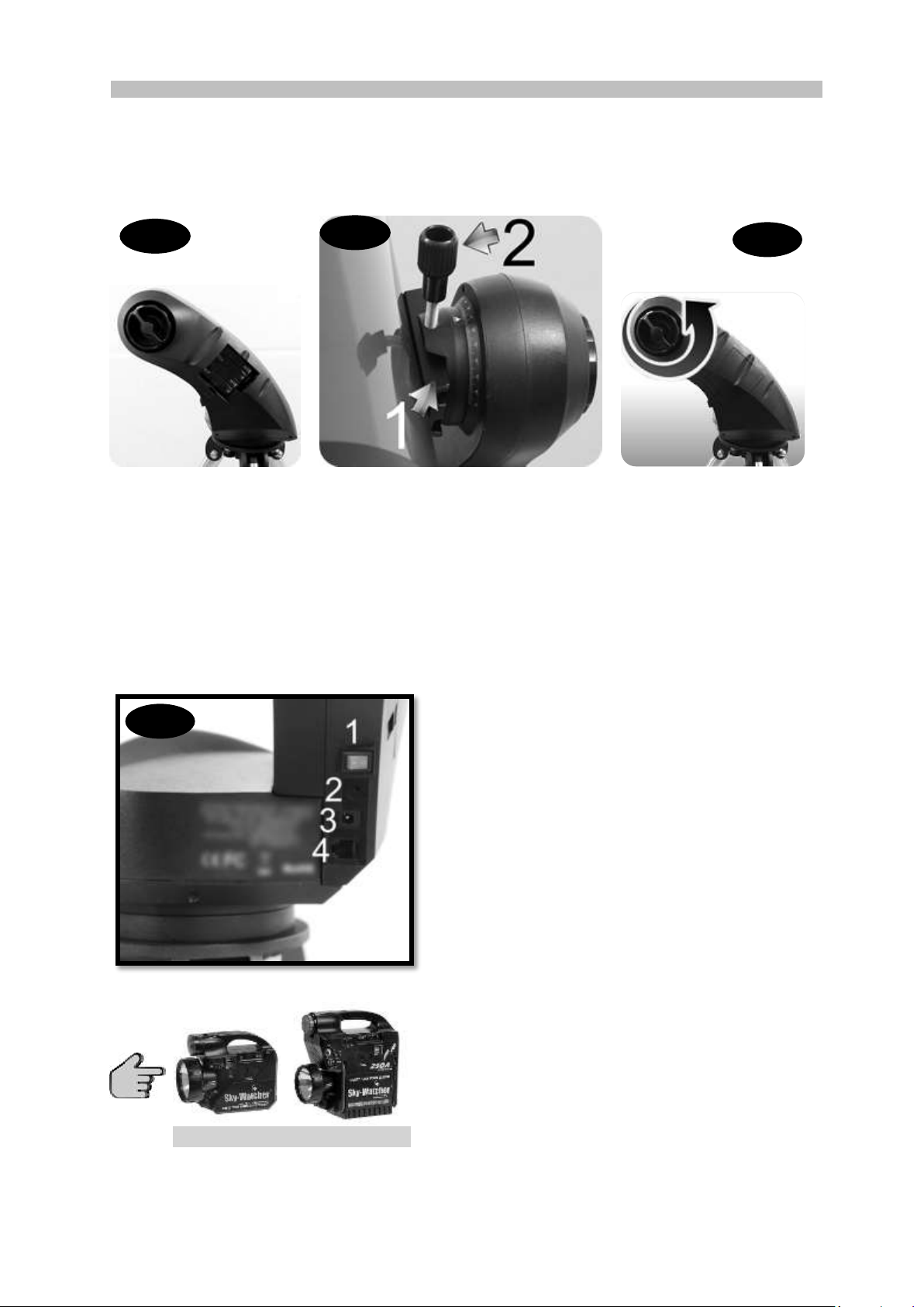
Optional 7 AH and 17 AH batteries
If you often use your Star Discovery mount it
may be useful to use a Sky-Watcher
rechargeable battery (7AH or 17AH) that can be
directly connected on the external power outlet
of the Star Discovery mount (Fig. 7.3).
These batteries are designed to provide a long
lasting and stable power to your mount.
Fig. 4
Fig. 5
Fig. 6
Fig. 7
Install the mount’s head on the base so the three threads [shown by arrows in (Fig. 2)] are
aligned with the three screws on the base [shown by arrows in (Fig. 1)].
Tight the three screws from the base onto the head threads [shown by an arrow in (Fig. 3)].
Be sure the head is secure onto the base.
If not done yet, please install 8xAA cells inside the box located on the external side of the
mount’s arm. To open the box, gently lift the panel with one finger. Please note the cell
holder gets place for 4xAA cells on one side, and 4xAA more on the other side. Please insert
the cells with wright polarity. When done close the panel (Fig. 4).
To install a telescope, loosen the handle screw (Fig. 5.2) until you can slide the telescope
dovetail bar (Fig. 5.1) inside the bracket. Once inserted, tighten the handle screw (Fig. 5.2)
until the dovetail bar on the telescope tube is securely fastened on the mount. Adjust the
clutch knob (Fig. 6) to obtain a locking force enabling the main tube to be pushed manually
while staying steady once released.
The final step is to connect the controller to the
mount. On the arm side, in position 4 (Fig. 7.4) a
RJ12 connector (which looks like a wall phone
connector but with 6 contacts instead of 4) is
present.
Please check that the power button on position 1
(Fig. 7.1) is OFF, like shown on the picture.
If you have the hand controller (SD-Track model)
please plug it inside the connector on position 4.
If you have the SynScan Version 4 (SD-GoTo
model) please first connect the larger connector
with 8 contacts (RJ45 model) inside the
corresponding slot on the SynScan Version 4,
then the 6 contacts connector to the slot on
position 4.
4
Page 6
Part II: Getting Started
TELESCOPE
D=130mm F=650mm
Coated Optics
We need to know the focal length of the telescope. This
length is always written on the sticker as F= xxx mm, by
example F=650mm. To calculate the magnification with the
23mm eyepiece we use the formula:
Magnification = 650/23 = 28.26x, so 28x.
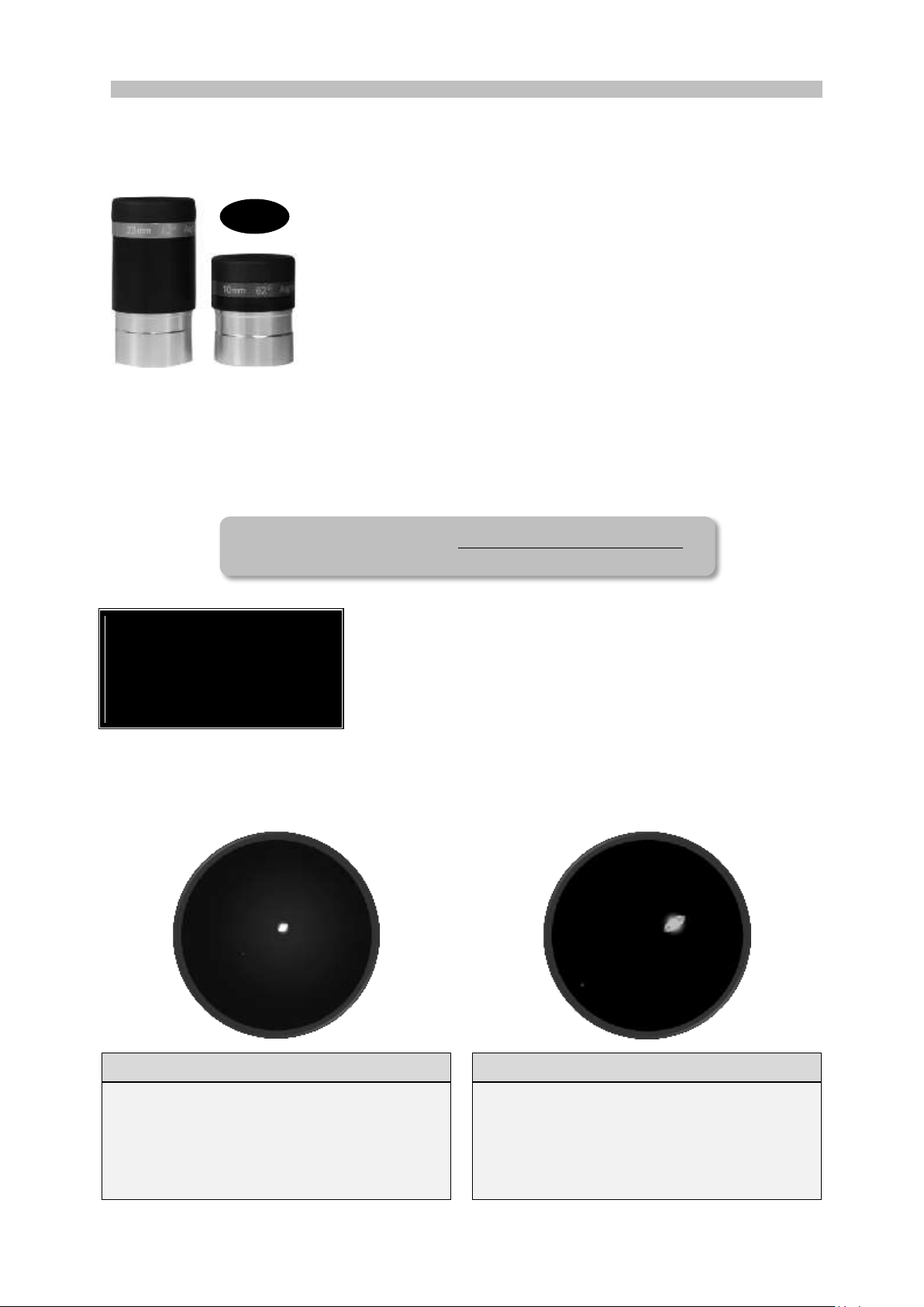
Illustration of Saturn with the 23mm EP
Illustration of Saturn with the 10mm EP
On this graphical representation of the field
of view of the 23mm eyepiece Saturn is
very bright but quite small in size. The rings
are barely visible but Saturn’s moons will be
visible in the field of view.
On this graphical representation of the field
of view of the 10mm eyepiece Saturn is
less bright but have an interesting size. The
rings are well visible but most Saturn’s
moons are outside the field of view.
Fig. 8
Preparing the telescope for an observation
If you already know how to use a telescope you may skip this section, otherwise this section
will help you to understand the basics you need to make an observation.
Inside the instrument box you will find two eyepieces, one with a
gold band written “23mm 60° Aspheric” and a shorter one with a
blue band noted “10mm 60° Aspheric” (Fig. 8).
The eyepiece is a special magnifying glass that enlarges the
image the telescope provides at the focal point. Without the
eyepiece our eye will not be able to bring the image of the
telescope in focus, in other words we cannot see directly the
image.
For information these eyepieces are called “1’
metallic nozzle at the end of the eyepiece. Any eyepiece having this 1
be used on your telescope. This size, 1
1/4
The other information written on the eyepiece is its focal length, expressed in mm. It is
important because the enlargement provided by the eyepiece is directly linked to its focal
length. Here is the formula to calculate the enlargement provided by an eyepiece:
1/4
inches eyepieces” due to the diameter of the
inches is standard.
1/4
inches nozzle can
The 23mm eyepiece will provide less magnification than the 10mm eyepiece, but will provide
a more luminous image and a larger field of view.
5
Page 7
Part II: Getting Started
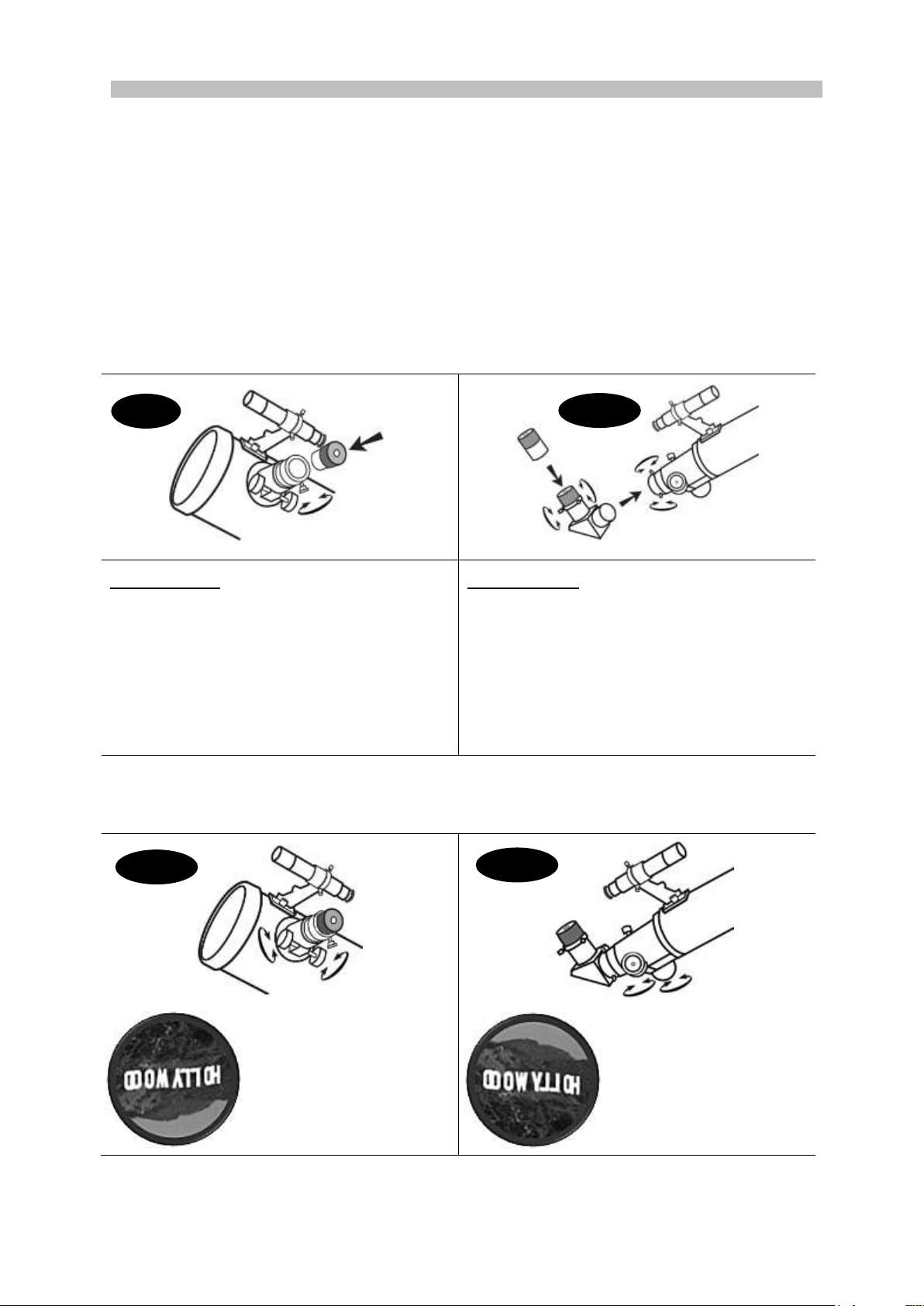
For reflectors (Fig. 9):
Unscrew the thumbscrews on the end of the
focus tube, then insert the desired eyepiece
and re-tighten the thumb screws to hold the
eyepiece in place.
For refractors (Fig. 10):
Unscrew the thumbscrews on the end of the
focus tube to insert the diagonal and retighten thumbscrews to secure the diagonal
in place.
Loosen the thumbscrews on the diagonal to
insert the desired eyepiece into diagonal and
secure it by re-tightening the thumb screws.
Once the eyepiece is installed, slowly turn the focus knobs (Fig. 11), one way or the other,
until the image in the eyepiece is sharp. The image usually has to be finely refocused over
time, due to small variations caused by temperature changes or other factors.
Inside reflectors the
image is upside-down.
It is normal and has no
effects on observations
Inside refractors with the
star diagonal the image
is inverted left-to-right
like in a mirror.
It is normal and has no
effects on observations
Fig. 9
Fig. 10
Fig. 11
Fig. 11
The 23mm eyepiece delivers a larger view of objects with fewer enlargement, as if “seen
from a further distance” than with the 10mm. When observing it is advisable to first use the
23mm to center the object inside the field of view to get an “overview” of the surroundings,
then use the 10mm to get “closer” and discern more details. Needless to say the graphical
representation is just for understanding. The real view inside your telescope will be more
detailed, crisper and will deliver faint details.
To understand how to use an eyepiece with your telescope it is better to experiment in bright
daylight when it is easy to locate and manipulate the different parts. The first step is to install
your mount and telescope outside, as explained in the previous chapter. As you can freely
move the telescope by hand you can let the mount power OFF for now.
Please remove the dust caps on the telescope and eyepieces and store them in a convenient
place. Please install the eyepiece as follow:
After experimenting with eyepiece you can take advantage to have your telescope set up and
proceeds to next chapter: “aligning the finder scope”
6
Page 8
Part II: Getting Started
NEVER LOOK DIRECTLY AT THE SUN WITH
THE FINDER SCOPE. IT COULD IMPAIR
DEFINITIVELY YOUR VISION.
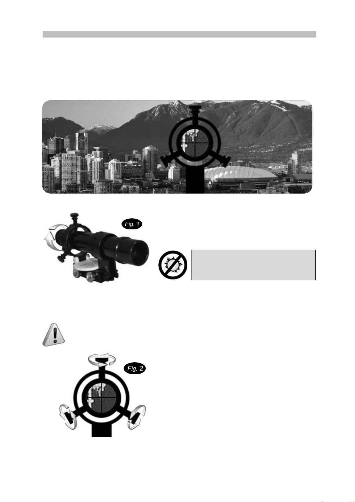
Aligning the finder scope
The 6x24 finder scope is a small fixed magnification scope mounted on the optical tube.
When it is correctly aligned with the telescope, objects can be quickly located and brought to
the center of the field.
The alignment should be done at first use and over time if the alignment is no more accurate.
Alignment is best done outdoors in day light when it's easier to locate objects
If it is necessary to refocus your finder scope sight
on an object that is at least 500 meters (or yards)
away, then turn the knurled ring at the end of the
finder scope until the image is in focus (Fig. 1).
Choose a distant object that is at least 500 meters (or yards) away and point the main
telescope at the object. Adjust the telescope so that the object is in the center of the view in
your eyepiece.
The image in the finder scope is upside-down. This is normal and has no incidence
on observations.
Check the finder scope to see if the object, centered
in the main telescope view, is centered on the
crosshairs. If not adjust the three small screws to
center the finder scope, as shown in (Fig. 2).
Do not over tighten the screws when aligning the
finder scope.
7
Page 9
Part III: Astronomy with the Hand Control
1
Part III: Astronomy with the Hand Control
If you are using the SynScan version 4 (different hand controller from the
one pictured below) please refer to page 16 for proper setup instructions.
In order to allow the celestial object tracking function to work properly, the
Star Discovery mount needs the input of the local latitude. Without this
information the mount will not be able to track objects in the sky.
How finding your local latitude? The easiest way is to use a GPS (maybe one
is embedded on your smartphone), or by using Google Earth. It is best to get
the local latitude in decimal notation (like 44.504 °) instead of the “ddmmss”
format (like 44°30’20”). It will be easier to use decimal format1.
Please note down the value, it will be used while setting up the mount.
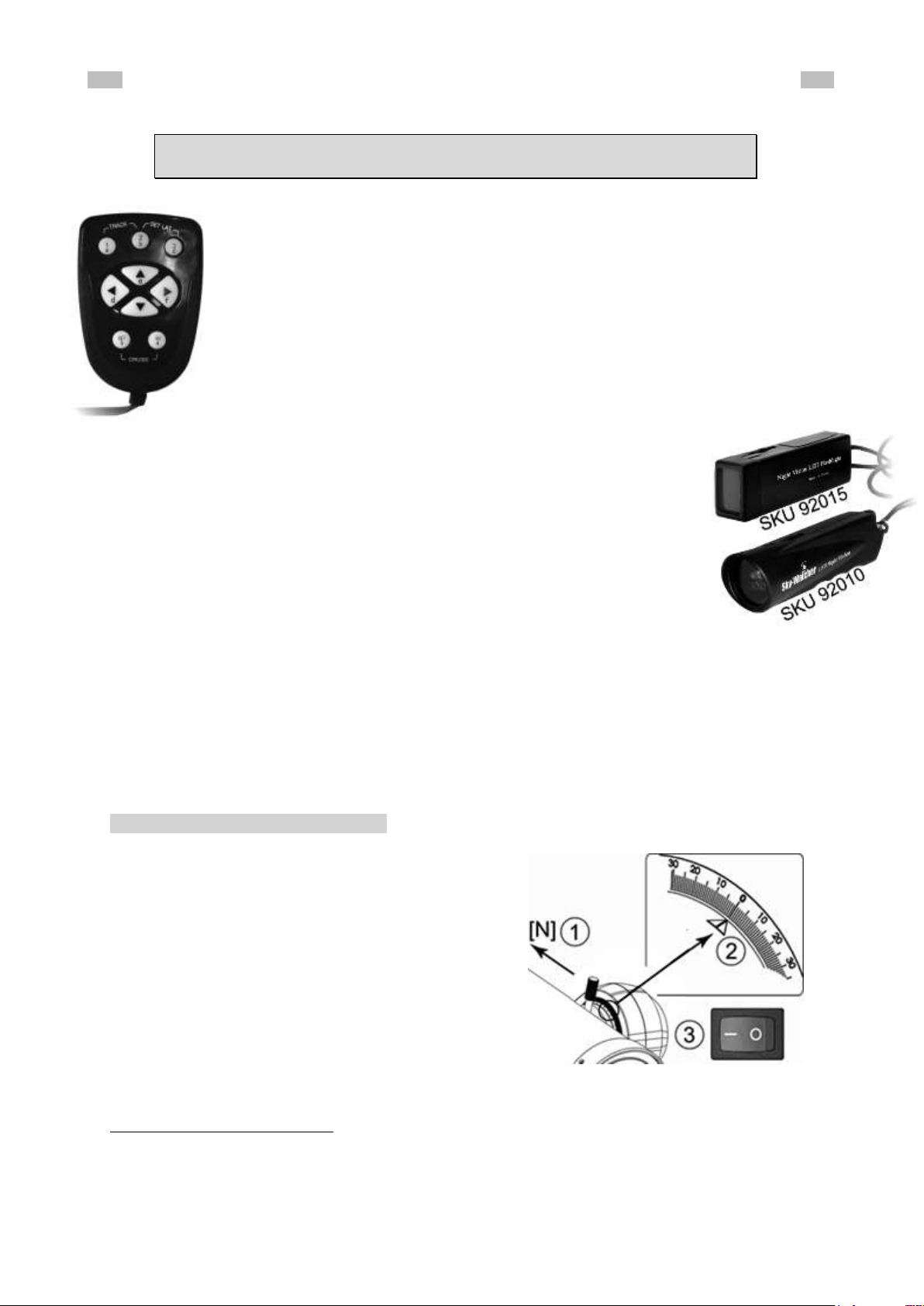
The next tools needed are a flashlight and a good compass. Maybe your
smartphone has a digital compass? It will do nicely. Otherwise any “old
fashioned” compass will do the job.
Don’t take a high power flashlight, a strong light beam will bedazzle you and
you will not see clearly the stars for a while. Seasoned astronomers use a
dim red light to protect their night vision. Sky-Watcher proposes two red light
models: SKU-92015: a voltage regulated LED flashlight that emits soft red
light to assist telescope operation with adjustable brightness and SKU-92010:
a multipurpose flashlight with adjustable brightness that can be switched back
and forth between red light for night vision and regular white light. Please ask
your reseller for availability.
Please setup your mount and connect all accessories as explained on page 3 and 4. Also
please check your mount is not powered, the power button is OFF.
When using the mount for the first time or at different latitudes please set or reset the initial
position. (If at the same latitude, you may setup the mount by following the instructions on
next page, last paragraph)
Initial setup
For users in Northern Hemisphere
For the initial setup we need to “tell” to the Star
Discovery mount how it is oriented. Level the tripod
top by adjusting the tripod leg. At this point the
compass will come handy to find the north.
1. Aim the main tube at North horizontally
2. Rotate the altitude axis until the altitude scale
reads 0 (according to the enlarged view to the
right)
3. Restart power.
The mount is now ready to receive the northern
latitude input. (Continued next page)…
To convert sexagesimal (ddmmss) format to decimal degrees use the following formula :
Decimal degrees = dd+mm/60+ss/3600
By example 23°24’36” = 23+24/60+36/3600 = 23+0.4+0.01 = 23.41°
8
Page 10

(Continued) To set the northern latitude:
4. Rotate the altitude axis to enable the altitude
scale to read local latitude (according to the
enlarged view to the right – set to 21° on
image as example).
5. By pressing the handset button 2 and 3
simultaneously, the Star Discovery Mount will
recognize the local latitude.
Aim the telescope towards the object under
observation: the mount will begin auto tracking.
For users in Southern Hemisphere
For the initial setup we need to “tell” to the Star
Discovery mount how it is oriented. Level the
tripod top by adjusting the tripod leg. At this
point the compass will come handy to find the
north.
1. Aim the main tube at North (even if we are in
the Southern Hemisphere it should be oriented
North)
2. Rotate the altitude axis to enable the altitude
scale to read local latitude (according to the
enlarged view to the right – set to 21° on
image as example).
3. Restart power.
The mount is now ready to receive the southern
latitude input.
To set the southern latitude:
4. Rotate the altitude axis until the altitude scale
reads 0 (according to the enlarged view to the
right)
5. By pressing the handset button 2 and 3
simultaneously, the Star Discovery Mount will
recognize the local southern latitude.
Aim the telescope towards the object under
observation: the mount will begin auto tracking.
Part III: Astronomy with the Hand Control
Quick Setup
If using the mount in the same latitude location (mainly
at the same place the initial setup took place), you can
do a quick setup.
1. Aim the main tube at North horizontally (even
if you are in the southern hemisphere).
2. Restart the power.
The mount will begin auto tracking.
9
Page 11

Part III: Astronomy with the Hand Control
Tracking accuracy depends on multiple factors, such as: level of the base,
accuracy of pointing to true North before turning power on, accuracy of setting
local latitude, celestial object types: Sun, Moon, planet or stars or the position of
the target in the sky. It is normal to find that the celestial object still drifts slowly in
the eyepiece of the telescope during tracking; however the drift will be much
slower compared to a telescope without tracking function.
Using the Hand Controller for Astronomy
The basic movements of the Star Discovery mount are directional movement, slewing, and
tracking. The tracking rate is sidereal rate. Sidereal rate means the Star Discovery mount will
move automatically on both vertical and horizontal axis to keep a sky object centered on the
field of view.
The directional keys (Fig.1) are used to move the mount. The four
direction buttons are used to rotate the mount horizontally and
vertically. If two opposite buttons are pressed at the same time, only
the button first pressed will respond. AZ (azimuth) and ALT (altitude)
axis can be adjusted at the same time.
The slewing speeds (Fig.2) allow the user to choose from 5 rotating
speeds by pressing any of the 5 other buttons. Speed 1 is the slowest
and Speed 5 is the fastest.
Speed 1 and Speed 2 are for centering an object in the eyepiece of
the telescope.
Speed 3 and 4 are for centering an object in the red dot finder of
the telescope.
Speed 5 is for rotating the mount at full speed.
Other function:
The celestial object tracking function can be switched on/off by
simultaneously pressing the buttons 1 and 2. While tracking, the
backlight of the button representing the current selected speed will
flash. If tracking is off, the backlight will be continuously lit.
Equatorial Mode Tracking
The hand control can also control a mount tracking under equatorial mode for short focal
length astrophotography.
1. Polar-align the mount (Set up the mount with its vertical axis pointing to the celestial
pole using a strong ball head or with an equatorial wedge.)
2. Press and hold the SET button on the keypad and then turn on power. Now the
azimuth axis will start rotate at sidereal rate to compensate sky drift caused by the
earth’s rotation.
3. The tracking direction is opposite in Northern hemisphere and Southern hemisphere,
thus user should set the local latitude correctly before turning on the equatorial mode
tracking.
10
Page 12

Part IV: Terrestrial Photography
IMPORTANT NOTE:
PLEASE CHECK CAREFULLY THAT YOU HAVE INSERTED THE
MOUNTING BRACKET WITH THE METAL PLATE FACING THE
BLOCKING SCREW.
INSERTING THE MOUNTING BRACKET ON THE WRONG SIDE
MAY BREAK THE MOUNTING BRACKET WHILE TIGHTENING
THE BLOCKING SCREW OR MAY SUDDENLY FALL OFF WITH
ACCESSORIES LOADED DURING OPERATIONS.
Part IV: Terrestrial Photography
The Star Discovery mount is also perfectly suited to
shoot amazing panoramic images or do video cruising
automatically. But not only… It is also perfect for
lightweight astrophotography, time lapse photography,
wide view and panorama photography, video panning
and so many more activities.
The Star Discovery mount is capable of automatically
moving to various preprogrammed positions and
controls the camera shutter to take a picture at each
position automatically, taking the complexity out of
producing panoramic video or photographs.
The Star Discovery mount also supports Sky-Watcher
latest patented Freedom Find (dual-encoder)
technology. With two encoders the mount will keep
track of stored position even if the mount has been
manually rotated. A feature many nature photographers
awaited for so long.
Installing the Mounting Bracket
Before installing the mounting bracket please note the bracket has a
metal plate reinforcement on one side, as shown in (Fig.1). This
metal plate should face the blocking screw on the vertical axe.
Gently slide the mounting bracket inside the EQ5 style dovetail
support, roughly to the middle or the height of the mounting bracket.
Secure the mounting brackets in place by tighten the blocking
screw.
You can assemble on the mounting bracket any device having a
standard photo thread (1’ ¼ 20TPI), like a camera, a camcorder
or a spotting scope.
To assemble and secure a camera body on the mounting bracket
you need to align the thread inside the camera body with the
screw (step 1), then tighten the screw until the camera is tight
(step 2).
Don’t over tight the screw; you may damage the camera
body’s thread and/or the mounting bracket screw.
11
Page 13

Part IV: Terrestrial Photography
The secondary plate is designed to support light accessories (< 400g).
Please do not install a digital single lens reflex camera (DSLR) or a spotting scope
on the secondary accessory plate. The mounting bracket may break, or the
secondary accessory plate may bend over the accessory installed below.
It is also possible to attach two devices on the mounting
bracket by using the secondary accessory plate. You will
find the secondary accessory plate and two screws inside
the box.
To mount the secondary accessory plate: locate two
threads on the internal side of the mounting bracket (part
1) and use the two screws (part 2) to assemble the
secondary accessory plate (part 3) on the mounting
bracket (part 1). Take care to mount the secondary
accessory plate with it screw on the same side as the
screw of the mounting bracket.
General Operations
The hand control always activates the celestial object tracking
function after power is turned on. For terrestrial application, user
could press buttons "1" and "2" simultaneously to turn off the
tracking function to prevent the mount moving automatically.
Please setup your mount and connect all accessories as explained on page 3 and 4 before
using your mount for terrestrial photography or videoing.
Setting and retrieving preset positions
The hand control can store 6 preset positions and retrieve these positions when required.
Point the mount (with spotting scope, camera etc.) to a spot of interest, and then press
button (SET) plus one of the buttons (a) to (f). The current position of the mount will be
stored and represented with that button (a to f).
Press button (GO) plus one of the buttons (a) to (f) and the mount will slew to the preset
position represented by that button (a to f).
To ensure the best accuracy for your position choices, it is important that you use
the "up" and "right" direction buttons as the final keys before you actually set your
position.
12
Page 14

Part IV: Terrestrial Photography
If one of (a) to (f) preset position is stored with the position which is the same
its previous one, then it will be skipped during the cruising. For example, if (b),
(c) and (d) are preset with the same position which is different from (a) and (e)
then the cruise sequence will be a->b->e positions while c and d positions are
skipped.
A position which is not set after turning on power will also be skipped during
cruising.
AP-R3C(CANON C3)
3.04.002.0074
AP-R1N(NIKON N1)
3.04.002.0075
AP-R3N(NIKON N3)
3.04.002.0077
AP-R3L(OLYMPUS OP12)
3.04.002.0078
AP-R1S(SONY S1)
3.04.002.0079
AP-R2N(NIKON N2)
3.04.002.0076
Camera Cruising Function
The hand control can control a camera to take pictures at up
to 6 preset positions (a to f) using the SNAP interface of the
Star Discovery mount. The camera used for this application
should have an external shutter control port which can
connect to the mount's SNAP port with a proper cable. The
SNAP port is a 2.5 mm 3-segment stereo jack and the trigger
signal connects to the tip and base segments.
You can order an optional cable for your
camera from your local reseller. The list shows
some available optional cables.
Before using the camera cruising function you have to select at least two preset positions as
explained in the previous chapter “Setting and retrieving preset positions”
Press one of the buttons 1-5 to choose a slewing speed, 1 is very slow, 5 is very fast. Slow
speeds are recommended with heavy loads, like a camera with a long focal-objective.
1. Press buttons (GO) and (SET) simultaneously to start the Camera Cruising. The
mount will slew to and stop at the pre-stored positions one by one from (a) to (f).
When the mount stops, it will send a signal to trigger the attached camera to take a
picture.
2. The mount will stop at the last position for about 1 minute before it re-starts the
cruising again. This function can be turn on/off by pressing (GO) buttons when the
mount is in Camera Cruising operation.
3. By default, when the mount stops at a pre-stored position, the active time of the
shutter triggering signal is 3 seconds. User can press button (a) to (f) and button
(DOWN) to change the time to 1, 2, 3, 4, 5, 7 and 10 seconds during the cruising. The
proper time depends on how long the camera takes to finish one exposure.
4. During the cruising, user can press the (SET) button to pause/resume.
5. Press buttons (DOWN) and (RIGHT) simultaneously to stop the cruising.
Video Cruising and Time-Lapse Photography Function
The hand control can also control the mount to cruise through up to 6 pre-stored positions
without full stop at the spots. This is for using a camcorder to record a continuous video or
taking time-lapse photography (video).
13
Page 15

Part IV: Terrestrial Photography
If one of (a) to (f) preset position is stored with the position which is the same its
previous one, then it will be skipped during the cruising. For example, if (b), (c)
and (d) are preset with the same position which is different from (a) and (e) then
the cruise sequence will be a->b->e positions while c and d positions are
skipped.
A position which is not set after turning on power will also be skipped during
cruising.
If both axes positions are changed between two preset points, the axis with
shorter slewing distance will slew at lower speed; both axes will stop at
approximate the same time.
1. Press one of the buttons 1-5 to choose a slewing speed. Speed 1, 2, 3 are for time-lapse
photography, speed 4, 5 are for normal video recording. Here is the speed table:
• Speed 1: 1 rotation per 24 hours.
• Speed 2: 1 rotation per 6 hours.
• Speed 3: 1 rotation per 3 hours.
• Speed 4: 1 rotation per 1.5hours.
• Speed 5: Approximate 2.5 degree/second
2. Press buttons (GO) and (DOWN) to activate the Video Cruising function. During the
cruising, the mount will send shutter release signal periodically.
3. During the cruising, user can press the (SET ) button to pause/resume the mount.
4. By default, when the mount sends shutter release signal from the SNAP port every 3
seconds for time-lapse photography. User can press button (a) to (f) and button (DOWN)
to change the interval to 1,2, 3, 4, 10, 40 and 60 seconds during the cruising.
5. Press buttons (DOWN) and (RIGHT) to stop the cruising.
Panoramic/Matrix Photography
The hand control can control a camera to take panoramic photos with the SNAP interface.
The camera must have an external shutter control port (see Camera Cruising Function
paragraph about SNAP interface), and a proper bracket should be used to attach the camera
on the mount (see Assembling and Installing the Mounting Bracket paragraph about
using the mounting bracket).
1. Set the camera’s field of view
• Level the camera on the mount. Turn off the power of the mount and then turn it on
again.
• Look through the viewfinder window of the camera or look at the life view LCD
display of the camera. As shown in the following figure, remember the object at the
corner of the view finder, and then rotate the azimuth and altitude axes of the mount
with the hand control to move the center of the view finder onto that object. Press
buttons (SET) and (a) to save the position. The Star Discovery mount will double the
movement to get the full field of view.
When taking panoramic pictures, the
mount will apply 30% overlap between the
pictures, as represented in the picture.
14
Page 16

Part IV: Terrestrial Photography
The field of view and altitude limits are saved in the hand control even after the
power is turned off. For the next panoramic photography session, the user does
not need to repeat the setting if these parameters do not change. User can
simply level the tripod and camera, turn on power and press button (a) and (c) to
start taking panoramic pictures. As the hand control always takes panoramic
photography after each power-on; it is required to set left/right limits of azimuth
for matrix photography.
2. Set the lowest altitude angle of photography: look through the view finder of the camera
and use the (DOWN)/(UP) buttons to slew the altitude axis to the desired lowest point of
photography, and then press button (SET) and button (DOWN) to save the position.
3. Set the highest altitude angle of photography: look through the view finder of the camera
and use the (DOWN)/(UP) buttons to slew the altitude axis to the desired highest point of
photography, and then press button (SET) and button (UP) to save the position.
4. Set the azimuth range of photography: look through the view finder of the camera and
use the Right/Left buttons to slew the azimuth axis to the desired left most point of
photography, and then press buttons (SET) and (LEFT) to save the position. Then use
Right/Left buttons to slew the azimuth axis to the desired right most point and press
(SET) and (RIGHT) buttons to save the position.
To take a 360 degree panoramic picture, it is just needed to save the same
position to (LEFT) and (RIGHT).
We recommend using the power-on position as the left limit of azimuth because
the mount will always return to the power-on position after it finishes the
photography.
5. Start panoramic photography.
• Press buttons (a) and (c) simultaneously to start taking panoramic pictures.
• The mount will start taking pictures from the preset lowest altitude angle, first move in
azimuth direction, then increase altitude angle gradually.
• After all pictures are taken, the mount will return to the original position (Power-on
Position).
• During taking pictures, user can press the (SET) button to pause. Release the (SET)
button will resume the operation.
• By default, when the mount stops to take a picture, the active time of the shutter
triggering signal is 3 seconds. User can press button (a) to (f) and button (DOWN) to
change the time to 1, 2, 3, 4, 5, 7 and 10 seconds during the cruising. The proper
time depends on how long the camera takes to finish an exposure.
• Press buttons (DOWN) and (RIGHT) to suspend the operation.
15
Page 17

Part V: Astronomy with the SynScan Version 4
If the (ENTER) button is not pressed, it is possible continuing to change the
speed while using the direction keys to slew the mount.
If there is no keypad operation in 5 seconds, the most recent speed will be kept
and the LCD display will return to the previous ones.
Part V: Astronomy with the SynScan Version 4
Do you know that the SynScan Version 4 hand controller is
able to fully drive the huge EQ8 mount?
“The EQ8 High Precision EQ mount is pier tripod - based. It
comes with a SynScan Version 4 hand controller, […]. The
patented Freedom Find (dual-encoder) technology allows the
telescope to be moved manually whenever the user wishes but with no need for re-alignment!”
The very same SynScan Version 4 hand controller is used on
the Star Discovery mount. The SynScan Version 4 handset
can drive the Sky Discovery mount to any object selected
from its huge 42000+ object database, including objects from
Messier, IC, NGC and Caldwell catalogs, the planets, named
stars, double stars, variable stars and even user-defined
objects like new comets.
The Star Discovery mount includes digital encoders and the
patented “Freedom Find
Watcher EQ8 mount. After moving to a new object the
telescope will automatically begin to track the new object
accurately. No re-setup is required in one observing session.
TM
” technology like the big Sky-
Moving the mount around
In many situations, like aligning the Star Discovery mount on bright stars, it will be needed to
move the mount at different speeds with the directional keys. Here is how to perform this
operation:
The left and right keys are used to control the movements of the
azimuth axis (The mount will move left or right) and the up and down
keys are used to control the movements of the altitude axis (The mount
will move up or down)
Pressing the (RATE/2) key will display the menu for choosing a slewing speed:
The LCD screen displays “Set Speed”, followed by the current speed as “Rate = *x”’.
Press a number between (0) and (9) to select a new speed.
Press the (ENTER) key to return to the previous display.
16
Page 18

Part V: Astronomy with the SynScan Version 4
Key
Speed
Usage
0
0.5X
One turn in 48h: very slow speed to accurately center objects inside a high
magnification eyepiece field of view.
1
1X
One turn in 24h: quite slow speed to center objects inside an eyepiece field
of view.
2
8X
One turn in 3h: slow speed to quickly re-center objects.
3
16X
One turn in 1.5h: medium-slow speed to quickly re-center objects on an
eyepiece field of view or accurately centering object in the finder.
4
32X
One turn in 45 min: medium speed to very quickly re-center objects on an
eyepiece field of view or centering object in the finder.
5
64X
One turn in 22.5min: high - medium speed to quickly re-center objects in the
finder.
6
128X
One turn in 675s: high speed to quickly re-center objects in the finder.
7
400X
One turn in 216s: high speed to move the mount to a given position.
8
600X
One turn in 144s: very high speed to move the mount to a given position.
9
MAX
Ultimate high speed of the mount to move the mount to a given position.
The following table lists the available speeds:
Initial setup
1. Once the mount has been leveled and powered (please see …), the SynScan Version 4
will start the initialization process by displaying the Firmware Version. Press (ENTER) to
proceed to the next step of the initialization.
User can slew the mount with direction keys in this step.
2. Warning Message Confirmation: The hand control will display a warning message
about the dangers of viewing the sun with a telescope.
• Press (ENTER) to confirm you have read the warning message and proceed to the
next step.
• Press (ESC) to return to the previous step (firmware version display).
User can slew the mount with direction keys in this step.
3. Setting Information of the Observing Site: The LCD screen will display “Set Longitude”
then “Set Latitude” in the first line, and display longitude then latitude in the second line.
• Press the numeric keys at the cursor position to fill the longitude or latitude digits.
• Use the scroll keys to change east/west longitude or north/south latitude when the
cursor blinks on the corresponding characters (E/W for longitude, N/S for latitude).
• Use the Left and Right direction keys to move the cursor.
• Press the (ENTER) key to confirm the input and proceed to the next step.
• Press the (ESC) key to return to the previous step (Warning Message Confirmation).
17
Page 19

Part V: Astronomy with the SynScan Version 4
4. Time Zone: The LCD screen will display “Set Time Zone” in the first line, and display the
current time zone in the second line.
• Use the scroll keys to change the leading “+” or “-” sign when the cursor is on it. The
“+” sign is used for time zones in the Eastern Hemisphere (Europe, Africa, Asia,
Oceania), while the “-” sign is used for time zones in the Western Hemisphere (North
and South America).
• Press the numeric keys at the cursor position to fill the time zone digits.
• Press the (ENTER) key to confirm the input and proceed to the next step.
• Press the (ESC) key to return to the previous step (Setting Information of the
Observing Site).
5. Date, Time and Daylight Saving Time:
• When “Date: mm/dd/yyyy” is displayed, enter the current date in the indicated
mm/dd/yyyy format (i.e. 10/24/2012 for Oct.24, 2012); press the (ENTER) key to
confirm and proceed to the next step. Press the (ESC) key to return to the previous
step.
• When “Enter Time” is displayed, enter the current local time in 24-hour format. (i.e.
18:30:00 for 6:30 pm). Press the (ENTER) key to display the entered time in 12-hour
format. Press the (ENTER) key again to confirm and proceed to the next step. Press
the (ESC) key to return to the previous step.
• When “Daylight Saving?” is displayed, use the scroll keys to select “Yes” or “No”.
“YES” indicates the time entered in the previous step is daylight saving time, while
“NO” indicates the time entered is in standard time. Press the (ENTER) key to
confirm and proceed to the next step. Press the (ESC) key to return to the previous
step.
6. Starting Mount Alignment: this is the last step in the hand control’s initialization
process. The screen will display “Begin Alignment? 1) YES 2) NO” to ask the user to
make a choice:
• Press (1) to start the alignment process.
• Press (2) to skip the alignment process.
Aligning the Star Discovery Mount
The menu offers two alignment methods: Brightest Star Alignment Method and 2-Star
Alignment Method. The difference between these two methods is that for the Brightest Star
Alignment Method the SynScan Version 4 proposes you two bright stars where in the 2-Star
Alignment Method you choose two alignment stars from a list.
The Brightest Star Alignment Method is best suited for beginners while the 2-Star Alignment
Method is recommended for users who can locate named stars on the sky.
The Brightest Star Alignment Method
Aligning the 1st Star:
1. Find the brightest stars in the current sky with
naked eyes, and estimate its horizontal region
(orientation).
2. The hand control displays “Select Region”. Use
the scroll keys to pick one of the eight regions
shown in the left picture, which matches the
horizontal region of the brightest star. Press
(ENTER) to confirm selection and proceed to the
next step.
18
Page 20

Part V: Astronomy with the SynScan Version 4
During this step the mount will select a medium speed allowing centering the star
in the finder field of view easily. If the mount is moving too slowly to the selected
region you can move the mount manually. If the proposed speed is inadequate
you can change it like explained in chapter Moving the mount around.
During this step the mount will select a slow speed allowing centering the star in
the eyepiece field of view easily. Don’t move the mount manually, otherwise you
will “overshoot” the star position and lost it. If the proposed speed is inadequate
you can change it like explained in chapter Moving the mount around.
During this step the mount will select a slow speed allowing centering the star in
the finder field of view easily. If the proposed speed is inadequate you can
change it like explained in chapter Moving the mount around.
If the 1st alignment star is a planet, the SynScan hand control will display
“Choose 2nd Star”. Repeat from Step 2 to complete the alignment process.
3. The hand control will generate a list of the
brightest stars within the selected horizontal
region. The list is sorted by the brightness of
the star and with the brightest stars at the
top of the list. Users can use the scroll keys
to browse the list. An example of the screen
display is shown in the left picture.
Note: the selected object can also be a
bright planet.
4. The screen will display “Point scope to “RR ZZ.Z’ TT.T’ ”, which means point the
telescope to RR region, the exact azimuth is ZZ.Z degree and the exact altitude is TT.T
degree. Use the direction keys on the SynScan hand control to move the mount until the
1st alignment star selected is in the center of the finder field of view, thus inside the
eyepiece field of view if the finder is accurately aligned. Press (ENTER) key to proceed to
the next step.
5. Now the screen will display “Ctr. to eyepiece” and the name of the selected 1st alignment
star. The star should be inside the eyepiece field of view. User can use the direction keys
to center it in the eyepiece and then press the (ENTER) key to proceed to the next step.
Aligning the 2nd Star:
1. If the 1st alignment star is not a planet, the LCD screen will display “Choose 2nd Star”;
otherwise, it will display “Choose 1st Star”. Use the scrolling keys to browse through a list
of star names and press (ENTER) key to pick the one on the screen as the 2nd alignment
star. The mount will then automatically slew and point the telescope towards the
2nd alignment star in the sky.
2. After the mount stops, the hand control will give a long beep and will display the name of
the selected 1st star on line 1 and “Ctr. to eyepiece” on line 2. Now the telescope should
point rather closely to the 2nd alignment star (generally, in the field of view of the finder
scope).
3. Use the direction keys to move the telescope to the 2nd alignment star. That is, center
the 2nd alignment star in the field of view of the finder scope, and then center it in the
field of view of the telescope’s eyepiece. Press (ENTER) key to confirm the centering of
the star and proceed to the next step.
19
Page 21

Part V: Astronomy with the SynScan Version 4
The mount can be manually moved to the star’s position, then direction keys
used on the SynScan hand control to move the mount to center the star in the
field of view of the finder scope. By default the SynScan hand control will select a
medium speed. Please see also chapter “Moving the mount around” to select
any other usable slewing speed.
During this step the mount will select a slow speed allowing centering the star in
the eyepiece field of view easily. Don’t move the mount manually, otherwise you
will “overshoot” the star position and lost it. If the proposed speed is inadequate
you can change it like explained in chapter Moving the mount around.
After pressing (ENTER) to complete the alignment process the SynScan hand
control will display the alignment menu again. Press the button (ESC) twice until
the SynScan hand control displays « CHOOSE MENU »
During this step the mount will select a slow speed allowing centering the star in
the finder field of view easily. If the proposed speed is inadequate you can
change it like explained in chapter Moving the mount around.
4. If the 1st alignment star is not a planet, the SynScan hand control will now display
“Alignment Successful”. Press (ENTER) to complete the alignment process.
The 2-Star Alignment Method
Aligning the 1st Star:
1. The LCD screen displays “Choose 1st Star” in the first line. Use the scrolling keys to
browse through a list of star names and Press (ENTER) key to pick the one on the
screen as the 1st alignment star.
2. Now the screen will display “Point scope to ZZZ zz.z’ TT tt.t’ ”, which means point the
telescope to the direction whose azimuth is ZZZ degree, zz.z minutes and whose altitude
is TT degree, tt.t minutes. This is also the direction of the selected 1st alignment star.
3. Press ENTER key to proceed to the next step.
4. Now the screen will display “Ctr. to eyepiece” and the name of the selected 1st alignment
star. The star should be visible in the field of view of the telescope’s eyepiece if the finder
is correctly aligned. Use the direction keys to center the star in the eyepiece and then
press the (ENTER) key to proceed to the next step.
Aligning the 2nd Star:
1. The LCD screen displays “Choose 2nd Star”. Use the scrolling keys to browse through a
list of star names and Press (ENTER) key to pick the one on the screen as the 2nd
alignment star. The mount will then automatically slew and point the telescope
towards the 2nd alignment star in the sky.
2. After the mount stops, the hand control will display “Ctr. to eyepiece” and the name of the
selected 2nd alignment star. The telescope should point rather closely to the 2nd
alignment star (generally, in the field of view of the finder scope.)
3. Use the direction keys to move the telescope to align with the 2nd alignment star. To
align, center the 2nd alignment star in the field of view of the finder scope, and then
center it in the field of view of the telescope’s eyepiece. Press (ENTER) key to confirm
centering of the star and proceed to the next step.
20
Page 22

Part V: Astronomy with the SynScan Version 4
Locating Messier Objects
Press the (M/4) shortcut key on the SynScan hand control. The
screen will display “Messier Catalog / Messier =” to wait for input of
the 3 digits Messier index number which is between 1 and 110.
Use the number keys on the keypad to enter a number at the
cursor position.
Use the left or right direction keys to move the cursor.
A 3-digit number starting with a 0 is acceptable. Ex. 001 = 01 = 1
Press (ENTER) key to proceed to the next step (continued on p24).
Locating NGC Objects
Press the (NGC/5) shortcut key to access the NGC catalog. The
screen will display “NGC Catalog / NGC =”. The NGC catalog index
number ranges from 1 to 7840.
Use the number keys on the keypad to enter a number at the
cursor position.
Use the left or right direction keys to move the cursor.
A 4-digit number starting with a 0 is acceptable. Ex. 0022 = 022 = 22
Press (ENTER) key to proceed to the next step (continued on p24).
Locating IC Objects
Press the (IC/6) shortcut key to access the IC catalog. The screen will
display “IC Catalog / IC=”. The IC catalog index number ranges from 1 to
5386.
Use the number keys on the keypad to enter a number at the
cursor position.
Use the left or right direction keys to move the cursor.
A 4-digit number starting with a 0 is acceptable. Ex. 0033 = 033 = 33
Press (ENTER) key to proceed to the next step (continued on p24).
After pressing (ENTER) to complete the alignment process the SynScan hand
control will display the alignment menu again. Press the button (ESC) twice until
the SynScan hand control displays « CHOOSE MENU »
4. The SynScan hand control will now display “Alignment Successful”. Press (ENTER) to
complete the alignment process.
Locating Objects
Once properly aligned (see previous chapter) the SynScan Version 4 can automatically point
any object from its huge 42000+ entries in its database, including all popular celestial object
catalogs and planets positions.
1. Selecting an object
21
Page 23

Part V: Astronomy with the SynScan Version 4
Locating Planets and the Moon
Press the (PLANET/7) shortcut key. The screen will display
“SOLAR SYSTEM” in the top row.
Use the two scrolling keys to select the planet through a list in the
bottom row, which includes: Mercury, Venus, Mars, Jupiter, Saturn,
Uranus, Neptune, Pluto, and the Moon.
Press (ENTER) key to proceed to the next step (continued on p24).
The Object Menu
Press the (OBJECT/8) key. The screen will display “OBJECT LIST”
in the top row and “Named Star” in the second row.
Use the two scrolling keys to select a menu from the list below:
a) Named stars (please see below)
b) Solar System (same as PLANET/7 button menu)
c) NGC Catalog (same as NGC/5 button menu)
d) IC Catalog (same as IC/6 button menu)
e) MESSIER Catalog (same as M/4 button menu)
f) Caldwell Catalog (please see below)
g) SAO Catalog (please see below)
h) Double stars (please see below)
i) Variable stars (please see below)
j) Deep Sky Tour(same as TOUR/1 button menu)
k) User Objects (same as USER/9 button menu)
Press (ENTER) key to select the desired menu.
The Named Stars (a), Double Stars (h) and Variable Stars (i) submenus
Once inside, use the two scroll keys to go through and find the
desired object in the list of star names.
Press the (ENTER) key to confirm the selection (continued on p22).
The Caldwell Catalog (f) submenu
Once inside, the screen will display “Caldwell Catalog / Cald. #=”
for a 3-digit Caldwell index number between 1 and 109 to be
entered in.
Press the (ENTER) key to confirm the selection (continued on p22).
The SAO Catalog (g) submenu
Once inside, the screen will display “SAO Catalog / SAO 0000xx”
to wait for input of the 4 left-most digits of the 6 digits SAO index
number (i.e. “SAO 0238xx”).
Press the (ENTER) key to confirm the selection and then the hand
control will find the first SAO number in the database that matches
the 4 left-most digits entered (i.e. “SAO 023801”)
(continued on p24)
22
Page 24

Part V: Astronomy with the SynScan Version 4
The User Defined Objects menu (up to 25 objects can be defined)
Defining New Objects:
Press the (USER/9) shortcut key. The screen will display “USER
OBJECT”. Press the scroll keys until “New Object” is displayed on
the screen, then press the (ENTER) key.
The screen displays “New Object 1)RA-Dec 2)Mount”. Press “1” to
enter R.A./Dec. coordinates for a celestial object; press “2” to enter
coordinates for a land object.
If the “R.A.-Dec.” coordinates is chosen, the screen displays the
coordinates to which the telescope is pointing to. If the “Mount”
coordinates is chosen, the screen will display the coordinates of the
mount’s two axes. The first number is the coordinates of the
azimuth axis, while the second number is the coordinates of the
altitude axis.
Use the left and right direction keys to move the cursor and the
numeric keys to edit the coordinates. The scroll keys can be used
to change the sign of the declination coordinates or the altitude
coordinates. Press the (ENTER) key after editing.
The screen will display “Save?”
Press the (ENTER) key again to start saving the coordinates.
Users should use the scroll keys to select a storage space index
number between 1 and 25 and press the (ENTER) key to save the
new coordinates.
Press the (ESC) key to proceed to the next step without saving the
coordinates.
The screen will now display “View Object?”
Press (ENTER) to slew the mount towards the coordinates entered.
Press (ESC) to exit without moving the mount.
Recalling Objects:
Press the (USER/9) shortcut key. The screen will display “USER
OBJECTS / Recall Object”.
Press the (ENTER) key.
Use the scroll keys to browse through a pre-defined objects list
which is indexed from 1 to 25, and then press (ENTER).
If the selected object has not been defined before, the SynScan hand
control will stay at this step for the choosing of another object; otherwise, it
will proceed to the next step.
The screen will display the coordinates of the selected object.
Press the (ENTER) key again to proceed.
The screen will now display “View Object?”
Press (ENTER) to have the mount start slewing towards the
selected object. If the object is a celestial object, the mount will
start tracking the object automatically after it finishes slewing.
Press (ESC) to exit.
23
Page 25

Part V: Astronomy with the SynScan Version 4
The Tour menu
The SynScan hand control can generate a list of the most famous deep
sky objects which appear in the current sky. Any proposed object can be
selected and the SynScan hand control can point the telescope toward it
automatically. This is the “Deep Sky Tour” function.
Press the (TOUR/1) shortcut key.
The screen will display “Deep Sky Tour” in the top row.
Use the two scroll keys to browse through a list of the common
names of the deep sky objects
Press (ENTER) key to select the current entry (continued below).
If the selected object is below the horizon at this time, the SynScan hand control
will display “Below horizon” for 2 seconds; otherwise, it will display the object’s
current azimuth and altitude.
2. An object has been selected:
By using the scroll keys, users can browse the following information of the object:
Current celestial coordinates, J2000 celestial coordinates, magnitude (MAG = ), rising
time (Rise :), transit time (Transit :), setting time (Set :), size (Size = ), associated
constellation (Constellation: ) and common name of For named stars, Distance to
Earth in light years(DIST.), Spectral type, Bayer Designated name, catalog(SAO, HIP,
HD) number are provided. For double stars, the separation angle (Separation: ) and
the position angle (Position Angle) are provided.
Press (ENTER) key to proceed to the next step.
3. Go to the selected object
The screen will display “View Object?”
Press the (ENTER) key to have the mount slew towards the target. When the mount
stops, the SynScan hand control will return to the previous step. The mount will also
automatically start tracking the object.
Press the (ESC) key to return to the previous step.
Users can press the (ESC) key to stop the mount. The screen will display “MOUNT
STOPPED!! Press any key…”. Users can press any key to return to the previous step.
Identifying Objects
1. Center the object to be identified in the telescope’s eyepiece.
2. Press the (INFO/0) shortcut key. The screen will display “Identify:
Searching…”. The SynScan hand control will look up the named
stars, planets, Messier objects, NGC objects, and IC objects within
a 5 degrees range centered by the object in the eyepiece.
3. The screen will display “No object found” if the SynScan hand
control cannot identify the object.
4. If an object is found within the 5 degree range, then the screen will
display the object’s name in the top row, and the deviation from
the object to the center of the eyepiece.
5. If multiple objects are found, use the scroll keys to browse through
the list of identified objects.
24
Page 26

Part V: Astronomy with the SynScan Version 4
6. Press the (ENTER) key to select an identified object and then use the scroll keys to read
its data, such as the J2000 celestial coordinates, magnitude (MAG=), rising time (Rise: ),
transit time (Transit: ), setting time (Set: ), size (Size=) and associated constellation
(Constellation: ), etc.
7. Press the (ESC) key to exit
The SynScan Version 4 menu tree
The SynScan Version 4 menu tree is a useful reference to the menus that the controller will
display when connected to the Star Discovery Mount. In this manual only the most important
functions were explained in detail to help the user to start observing with Star Discovery.
For further information you can download the latest version of the technical manual for the
SynScan version 4 on the Sky-Watcher websites:
http://www.skywatcher.com/downloads.php
http://ca.skywatcher.com/_english/05_service/01_download.php?cid=2
25
Page 27

Appendix: Tips for observing the sky
Appendix: Tips for observing the sky
Sky conditions
Sky conditions are usually defined by two atmospheric characteristics, seeing, or the
steadiness of the air, and transparency, light scattering due to the amount of water vapor and
particulate material in the air. When you observe the Moon and the planets, and they appear
as though water is running over them, you probably have bad "seeing" because you are
observing through turbulent air. In conditions of good "seeing", the stars appear steady,
without twinkling, when you look at them with unassisted eyes (without a telescope). Ideal
"transparency" is when the sky is inky black and the air is unpolluted.
Selecting an observing site
Travel to the best site that is reasonably accessible. It should be away from city lights, and
upwind from any source of air pollution. Always choose as high an elevation as possible; this
will get you above some of the lights and pollution and will ensure that you aren't in any
ground fog. Sometimes low fog banks help to block light pollution if you get above them. Try
to have a dark, unobstructed view of the horizon, especially the southern horizon if you are in
the Northern Hemisphere and vice versa. However, remember that the darkest sky is usually
at the "Zenith", directly above your head. It is the shortest path through the atmosphere. Do
not try to observe any object when the light path passes near any protrusion on the ground.
Even extremely light winds can cause major air turbulence as they flow over the top of a
building or wall.
Observing through a window is not recommended because the window glass will distort
images considerably. And an open window can be even worse, because warmer indoor air
will escape out the window, causing turbulence which also affects images. Astronomy is an
outdoor activity.
Choosing the best time to observe
The best conditions will have still air, and obviously, a clear view of the sky. It is not
necessary that the sky be cloud-free. Often broken cloud conditions provide excellent seeing.
Do not view immediately after sunset. After the sun goes down, the Earth is still cooling,
causing air turbulence. As the night goes on, not only will seeing improve, but air pollution
and ground lights will often diminish. Some of the best observing time is often in the early
morning hours. Objects are best observed as they cross the meridian, which is an imaginary
line that runs through the Zenith, due North-South. This is the point at which objects reach
their highest points in the sky. Observing at this time reduces bad atmospheric effects. When
observing near the horizon, you look through lots of atmosphere, complete with turbulence,
dust particles and increased light pollution.
Cooling the telescope
Telescopes require time to cool down to outside air temperature. This may take longer if
there is a big difference between the temperature of the telescope and the outside air. This
minimizes heat wave distortion inside telescope tube (tube currents). A rule of thumb is to
allow 5 minutes per inch of aperture. For example, your telescope would require at least 30
minutes cooling off to outside conditions. Tip: use this time for polar alignment.
Adapting your eyes
Do not expose your eyes to anything except red light for 30 minutes prior to observing. This
allows your pupils to expand to their maximum diameter and build up the levels of optical
pigments, which are rapidly lost if exposed to bright light. It is important to observe with both
eyes open. This avoids fatigue at the eyepiece. If you find this too distracting, cover the nonused eye with your hand or an eye patch. Use averted vision on faint objects: The center of
your eye is the least sensitive to low light levels. When viewing a faint object, don't look
directly at it. Instead, look slightly to the side, and the object will appear brighter.
26
Page 28

We want to ensure that your experience with a SkyWatcher product is the best it can be. To make that
happen we have a comprehensive technical and
customer support available, alongside with the list of
distributors and dealers worldwide, on our worldwide
internet site:
http://www.skywatcher.com
Sky-Watcher offers this product with the best available quality in
accordance with the legislation of the local market, and reserves
the right to modify or discontinue, without prior notice to you,
any model or style telescope.
27
 Loading...