

Page 1
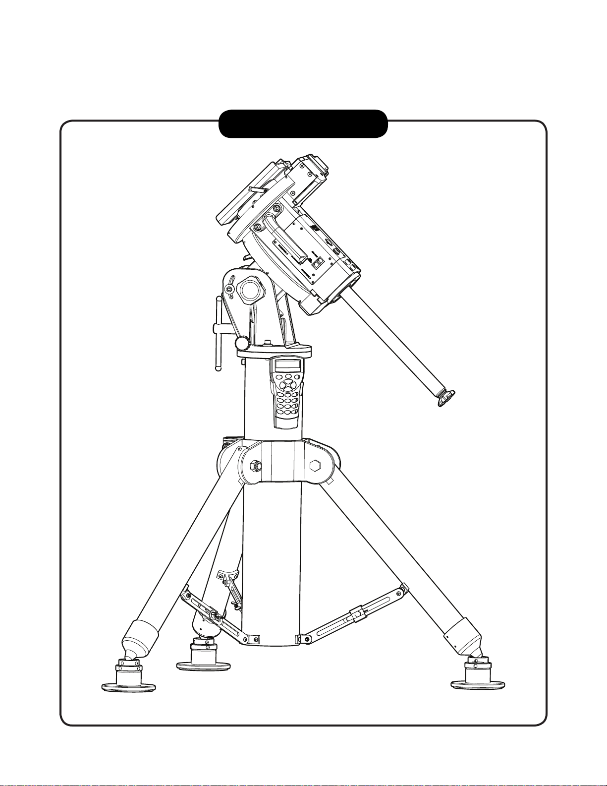
INSTRUCTION MANUAL
EQ8 Mount
Copyright © Sky-Watcher
100113V1
Page 2

CONTENT
PART I : SETTING UP THE EQ8 MOUNT
1.1 Setting Up the Tripod ...............................................................................................3
1.2 Putting On the EQ8 Mount .......................................................................................5
1.3 Installing the Counterweights ..................................................................................6
1.4 Installing the Telescope ...........................................................................................6
1.5 Balancing the Mount Load .......................................................................................7
PART II : POLAR ALIGNMENT
2.1 Prepare the Mount for Polar Alignment ................................................................. 8
2.2 Polar Alignment Using the SynScan Hand Controller ............................................ 9
2.3 Polar Alignment with the Optional Polar Scope .................................................... 9
2.4 The Orientation of the Polaris in Polar Scope .......................................................11
2.5 Align the Polar Scope ...........................................................................................12
PART III : ELECTRONIC CONTROL INTERFACE
3.1 Control Panel ........................................................................................................14
3.2 Panel Interface Components ................................................................................14
3.3 Pinout of the Interfaces .........................................................................................15
3.4 Power Supply Requirements .................................................................................15
PART IV : OTHER FEATURES OF THE EQ8 MOUNT
4.1 Freedom Find Function .........................................................................................16
4.2 Permanent Periodic Error Correction ....................................................................16
4.3 Batch Exposures Function ....................................................................................16
4.4 Auto-Home Function ............................................................................................16
APPENDIX I : SPECIFICATIONS
Dimensions ..................................................................................................................17
Specications ...............................................................................................................18
2
Page 3
PART I : SETTING UP THE EQ8 MOUNT
1.1 Setting Up the Tripod
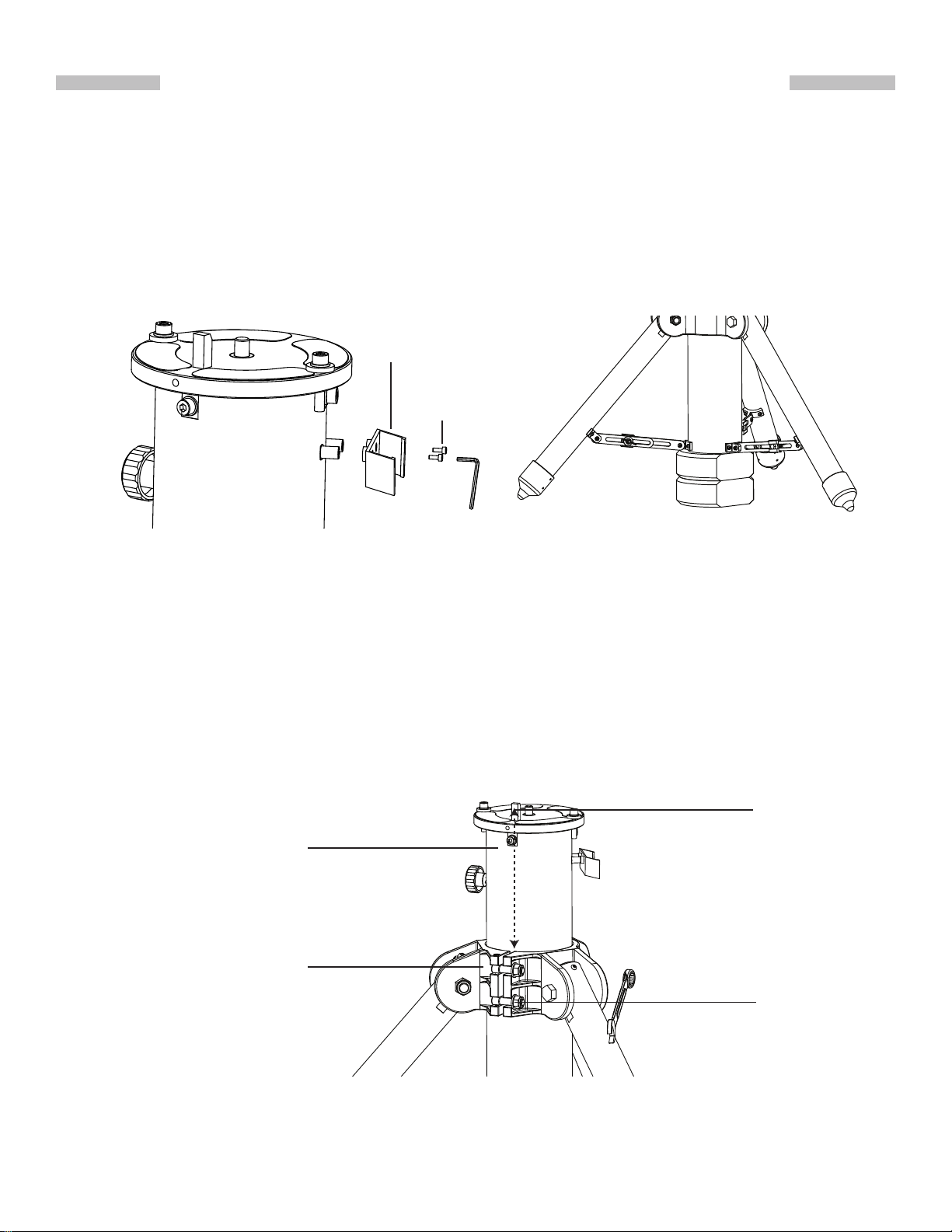
1. Fully expand the tripod legs on level ground.
2. Install the hand control bracket on the tripod. (Fig 1.1a)
3. Place one or two counterweight(s) just between the bottom of the central post and the
ground if there is enough space between them. This is a critical safety effort because the
counter weight(s) will prevent users from putting their feet under the central post uncon-
sciously. (Fig. 1.1b)
Hand Control
Bracket
M3X10
Screws
Fig. 1.1bFig. 1.1a
3. Fully release the clamp of the central post by loosening the two hex nuts on it with a 19mm
hex wrench (Fig 1.1c).
• The central post might fall freely when the two nuts are loosened. The counterweight(s),
which is (are) placed between the bottom of the central post and the ground earlier, will
support the central post and prevent any potential damages in such case.
• While loosening the two clamp nuts, to reduce the possible impact of the falling of the
central post, it is recommended to hold the tripod top, or to ll the gap between the top
of the counter weight and the bottom of central post with some soft material.
• User should loosen the two hex nuts alternately to make sure both of them are fully
loosened.
Dowel
Central Post
Align
Clamp
Nuts
Fig. 1.1c
4. After the clamp is fully released, rotate the central post in the clamp to roughly align the
dowel on the tripod top with the gap of the clamp. (Fig 1.1c)
3
Page 4
PART I: SETTING UP THE EQ8 MOUNT
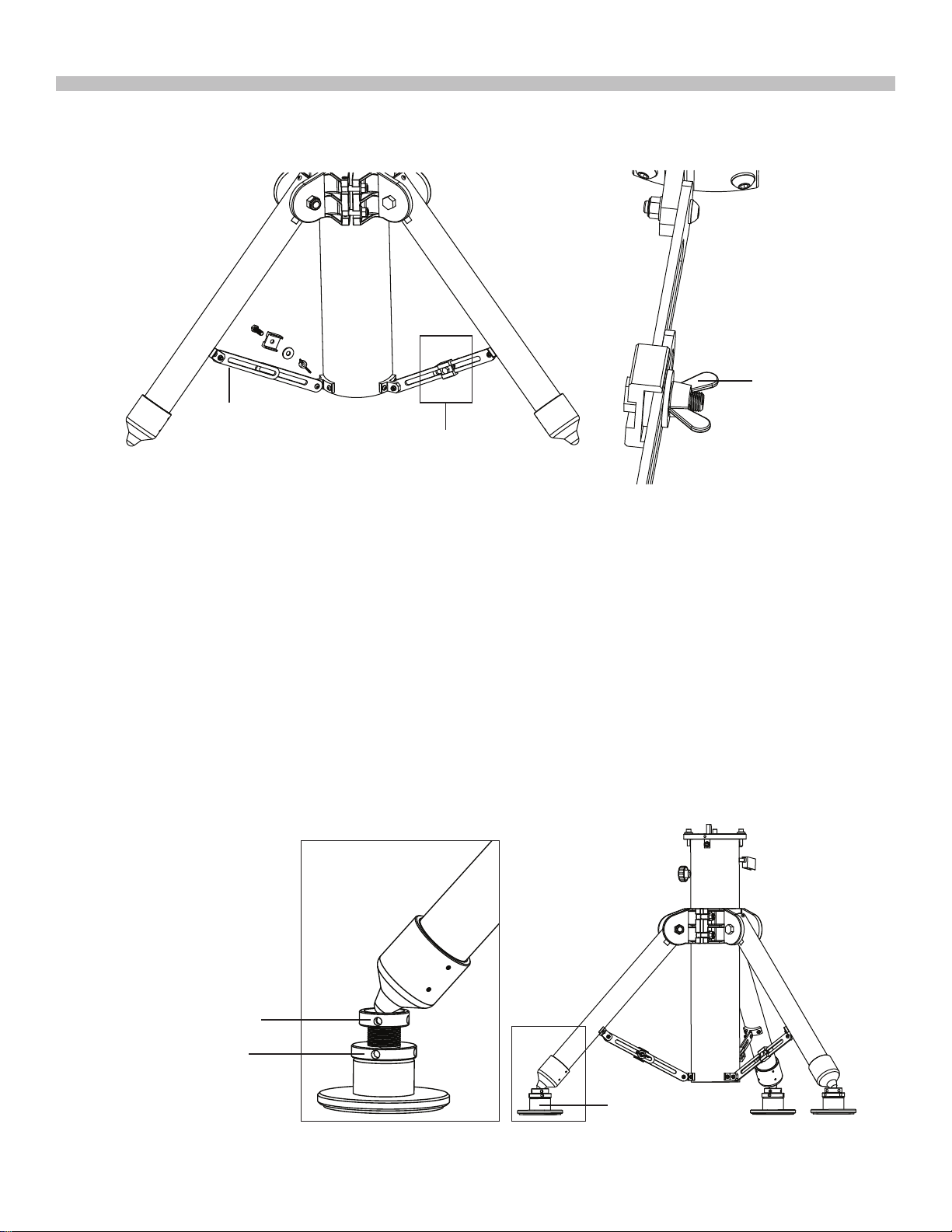
5. Assemble the 3 adjustable spider trusses as shown in F ig 1.1d and F ig 1.1e. Do not tighten
the thumb screws at this moment.
Thumb Screw
Spider Truss
See Fig. 1.4
Fig. 1.1d
Fig. 1.1e
6. Slide the central post up/down in the clamp (F ig . 1.1c) to the proper height and then tighten
the 3 thumb screws on the spider trusses to prevent the central post from falling.
7. Tighten both hex nuts on the clamp to secure the central post in the clamp. The two nuts
MUST be tightened in an alternate manner to avoid damage to the clamp. Do not over
tighten the two nuts.
8. The tripod can be placed directly on a level ground, or it can be placed on the 3 adjustable
stands as shown in Fig 1.1f.
• Put the tips of the tripod on the three adjustable stands.
• Turn the leveling screw to raise/lower a leg.
• Tighten the locking ring when the tripod top is leveled. (Fig. 1.1d).
• The small holes at the side of the leveling screw and the locking ring can accept a metal
bar for turning the screw and the ring.
Leveling Screw
Locking Ring
Adjustable Stands
Fig. 1.1f
4
Page 5
PART I: SETTING UP THE EQ8 MOUNT
1.2 Putting On the EQ8 Mount
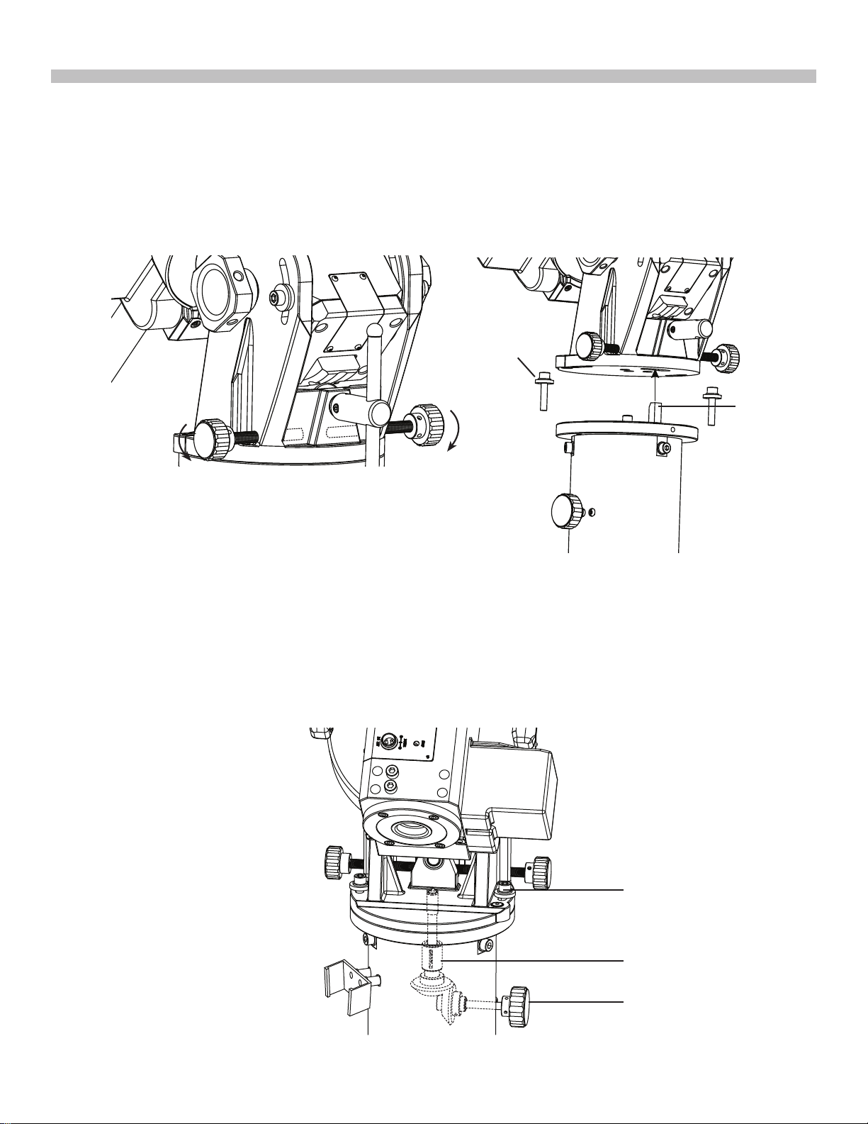
1. Loosen the two azimuth adjustment knobs on the EQ8 mount until there is sufcient space
between the two knob screws (Fig. 1.2a). Remove the two azimuth locking screws and
washers on the tripod top.
2. Align the metal dowel on the tripod top with the gap between the two azimuth adjustment
knobs; and then put the mount on the tripod top. (Fig 1.2b)
Azimuth
Locking
Screw
*
Dowel
*
Loosen
Azimuth Adjustment Knobs
Loosen
Fig. 1.2a
*
Fig. 1.2b
3. Apply the two azimuth locking screws with washers to slightly x the mount on the tripod
top. (Fig. 1.2c). Do not tighten these screws yet.
4. Turn the primary locking knob in clockwise direction to engage the primary locking shaft to
the threaded hole at the center of the mount’s bottom. Turn the knob until it is tightened.
(Fig 1.2c)
Azimuth Locking Screw
Primary Locking shaft
Primary Locking Knob
Fig. 1.2c
5
Page 6
PART I: SETTING UP THE EQ8 MOUNT
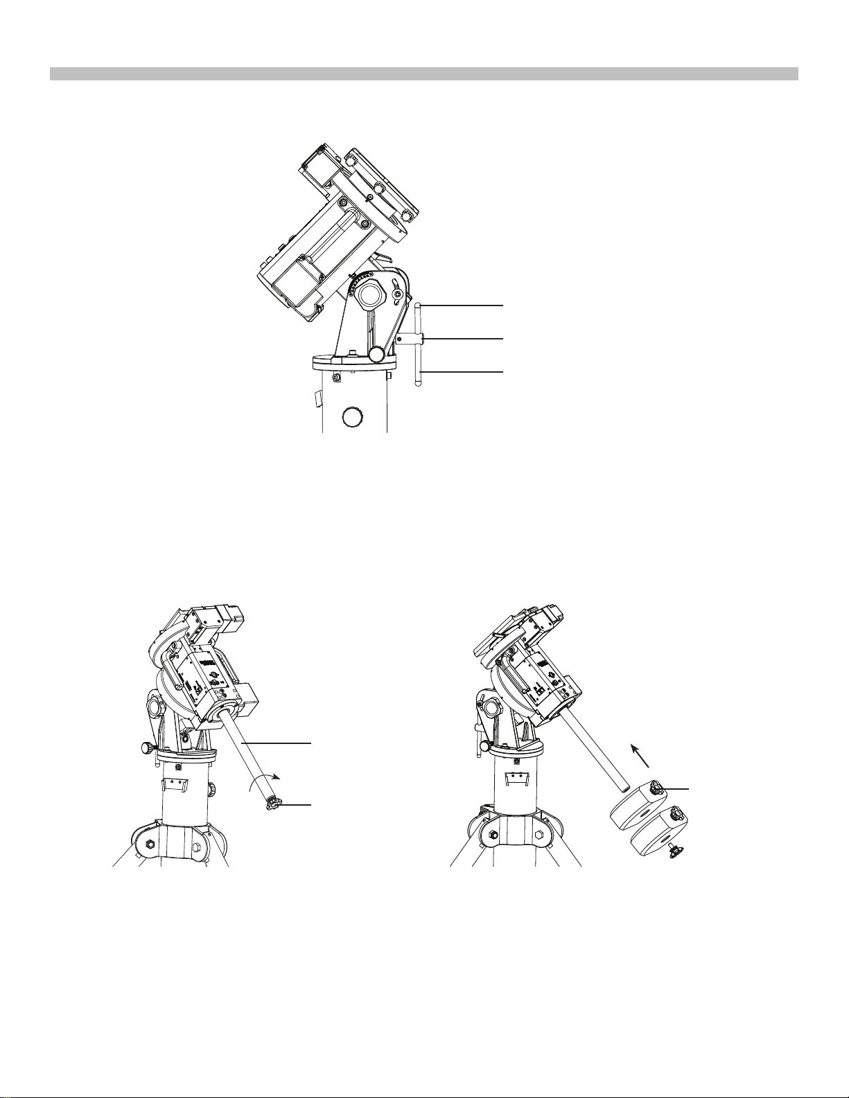
6. Slide the jackscrew handle in the hole at the end of the jackscrew shaft. Apply two ball
head screws on the handle. (Fig. 1.2d)
Ball-head Screw
Jackscrew Shaft
Counterweight Shaft
Fig. 1.2d
1.3 Installing the Counterweights
1. Screw the counterweight rod into the mount as shown in Fig. 1.3a.
2. Remove the stopper cap at the end of the counterweight rod.
3. Loosen the counterweight’s thumb screw and slide the counterweight onto the counter-
weight rod. Retighten the thumb screw to secure the counterweight on the rod. (Fig. 1.3b)
4. Replace the stopper cap to the end of the counterweight rod.
Counterweight
Rod
Lock
Stopper Cap
Fig. 1.3a
Thumb Screw
Fig. 1.3b
1.4 Installing the Telescope
1. Before installing a telescope, ensure:
• The counterweight rod is pointing towards the ground.
• All counterweights have been moved to the end of the counterweight rod.
• The R.A. Axis is secured by tightening the R.A. Clutch. (Fig. 1.4)
6
Page 7

PART I: SETTING UP THE EQ8 MOUNT
2. Release the Dec. clutch knob (Fig 1.4) and rotate the Dec. axis until the three knobs on
the saddle are facing upward and the dovetail groove is leveled (Fig 1.4). Tighten the
Dec. clutch again.
Arrow Sign
Saddle
Dec. Clutch
R.A. Clutch
Fig. 1.4
3. Loosen the three knobs on the saddle alternately until the width of groove is slightly wider
than the width of the dovetail bar on the telescope.
4. While holding the telescope horizontally, seat or slide the dovetail bar of the telescope to
the groove of the saddle. The pointing direction of the telescope should match the arrow
sign on the saddle (Fig 1.4).
5. Tighten the three knobs alternately to secure the dovetail bar in the groove.
Warning: Keep supporting the telescope until you are sure that it has been rmly at-
tached to the saddle.
1.5 Balancing the Mount
Once the counterweight and the telescope have been installed, the mount should be balanced
to reduce stress on the motor drive system, as well as to ensure smooth and accurate operation.
1. Loosen the R.A. clutch and rotate the R.A. axis until the counterweight rod is parallel to the
ground. Tighten the R.A. clutch.
2. Loosen the Dec. clutch and rotate the Dec. axis until the telescope is parallel to the ground.
Tighten the Dec. clutch.
3. Loosen the thumb screws on the counterweights.
4. Hold the counterweight rod with one hand, release the R.A. clutch and adjust the counter-
weights along the rod until the mount is able to remain stationary without support. Tighten
the thumb screws on the counterweights again.
5. Rotate the R.A. axis; the mount should remain relatively balanced along different angles.
Once this is conrmed, return the mount to its original position described in Step 1 and
tighten the R.A. clutch again.
6. Hold the telescope with one hand and release the Dec. clutch.
7. Slowly let go of the telescope and check for any rotational movements. If there is a
movement, slide the dovetail bar in the saddle to nd a balancing position at which the
telescope can remain stationary without support.
7
Page 8
PART II : POLAR ALIGNMENT
Prior to operating the EQ8 mount, it must be polar-aligned.
2.1 Prepare the Mount for Polar Alignment
1. Set up the EQ8 mount, counterweights, and telescope as described in PART I. It is recom-
mended to polar-align the EQ8 mount with all equipments installed.
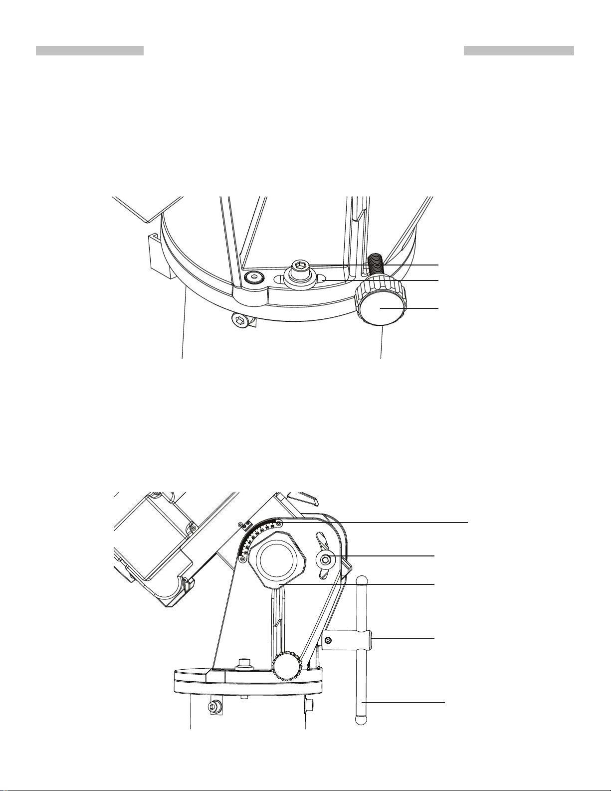
2. Loosen the primary locking knob and both azimuth locking screws; and then use the az-
imuth adjustment knobs to put the azimuth locking screws to the middle of the slots (Fig
2.1a). Tighten the azimuth locking screws slightly.
Azimuth locking screw
Slot
Azimuth adjustment
knob
Fig. 2.1a
3. Loosen the fork gripping knobs and screws (Fig 2.1b) on both sides of the EQ8 mount, and
then tighten them slightly.
4. Tighten the primary locking knob and then release it for 1/4 turn.
5. Move the tripod to align the R.A. axis to true north or south (for observing in southern hemi-
sphere) roughly.
6. Install the handle on the jackscrew and use the altitude jackscrew to set the latitude dial
reading local latitude (Fig 2.1b).
Latitude Dial
Fork Gripping Screw
Fork Gripping Knob
Latitude Jackscrew
Jackscrew Handle
Fig. 2.1b
8
Page 9

PART II: POLAR ALIGNMENT
2.2 Polar Alignment Using the SynScan Hand Controller
1. Choose 2-Star alignment or 3-Star alignment to align the mount, and then perform the po-
lar-alignment routine. Repeat these operations several times until the SynScan hand controller reports small polar alignment error after the 2-Star alignment or 3-Star alignment.
Refer to SynScan hand controller’s manual for detail operation instruction.
2. At the end of the polar-alignment routine, tighten the primary locking knob, and then tight-
en the azimuth locking screws, the fork gripping knobs and screws. User should observe
the alignment star in the eyepiece while alternately tightening these symmetric knobs and
screws; try to minimize the movement of the alignment star in the eyepiece.
3. It is recommended to remove the jackscrew handle after the polar-alignment has nished.
It can prevent unexpected changes to the polar-alignment.
2.3 Polar Alignment with the Optional Polar Scope
1. Install the polar scope assembly on the EQ8 mount as shown in Fig 2.3a.
Large knurled
ring
Fig. 2.3a
2. Verify whether the polar scope is aligned with the R.A. Axis. (Refer to the upcoming sec-
tion “Align the Polar Scope”).
3. Find the orientation of Polaris in Polar Scope. (Refer to the upcoming section “Orientation
of Polaris in Polar Scope”).
4. Use the latitude jackscrew and the azimuth adjustment knobs to polar-align the mount:
• Fig 2.3b shows the pattern in the eld of view (FOV) of the polar scope. If the image
appears blurred, rotate the knurled ring of the polar scope’s eyepiece to focus.
9
Page 10

PART II: POLAR ALIGNMENT
• For observing in Northern Hemisphere: Find the Polaris (The brightest star near the
North Celestial Pole) in the polar scope; then use the jackscrew and the two azimuth
adjustment knobs to move the Polaris to the proper position in the FOV of the polar
scope. (Refer to the upcoming section “The Orientation of Polaris in Polar Scope”).
Fig. 2.3b
• For observing in Southern Hemisphere: In the FOV of the polar scope, locate the 4
dim stars (Around Magnitude 5 to 6) which form the pattern like the “Octans” drawing
in the polar scope (refer to Fig. 2.3b). Rotate the large knurled ring of the polar scope
assembly to align the orientation of the “Octans” drawing to the 4 stars. Then use the
jack screw and the azimuth adjustment knobs to move the 4 stars to the 4 small circles
of the “Octans” drawing.
5. Tighten the primary locking knob, and then tighten the azimuth locking screws, the fork
gripping knobs and screws.
6. It is recommended to remove the jackscrew handle after the polar-alignment has nished.
It can prevent unexpected changes to the polar-alignment.
10
Page 11

PART II: POLAR ALIGNMENT
2.4 The Orientation of the Polaris in Polar Scope
As the Polaris is not located exactly at the North Celestial Pole, we can see it orbits the North
Celestial Pole in a polar scope. The large circle seen in the center of the pattern in Fig . 2.3b is
a representation of the Polaris’ orbit around the North Celestial Pole. When performing the polar alignment process, it is necessary to determine the orientation of the Polaris on the circle.
We can use the following 3 methods to get the orientation:
1. Locate Ursa Major (Big Dipper) in the sky, or alternatively Cassiopeia. Tighten the R.A.
clutch again. Rotate the large knurled ring of the polar scope assembly until either the Big
Dipper or Cassiopeia is aligned with their pattern in the FOV of the polar scope. At this
point, the location of the small circle on the large central circle of the pattern represents the
orientation of the Polaris in the polar scope. Put the Polaris to the center of the small circle
to nish the polar alignment.
2. Locate both the Polaris and the Kochab in the sky near the North Celestial Pole. The di-
rection from the Polaris to the Kochab can be used as proximity of the orientation of the
Polaris in the polar scope. Put the Polaris to the same direction on the large central circle
in the polar scope to nish the polar alignment.
3. At the end of the initialization of the SynScan hand control, after entering the proper local
longitude, latitude, date, time, and daylight-saving time, the SynScan hand controller will
display the message: “Polaris Position in P.Scope=HH:MM”. Imagine the larger circle in Fig.
2.3b as a clock’s face with 12:00 at the top, with the current time pointing to the “HH:MM”. The
orientation of the hour hand of the clock represents the orientation of the Polaris in the polar
scope. Put the Polaris to the same orientation on the large circle to nish the polar alignment.
Tips: To nd the top of the large circle in FOV of the polar scope, use the latitude jackscrew to
move the Polaris close to the top of the circle, and then use the azimuth adjustment knobs to move
the Polaris in the FOV horizontally. The middle point of the arc which was cut by the horizontal track
of the Polaris is the top of the large circle (Fig 2.4).
Top Point
Arc
Horizontal track of the Polaris
Fig. 2.4
Out of the three methods above, the rst two methods are somewhat less accurate, while the
orientation given by the SynScan hand controller is the most accurate.
11
Page 12

PART II: POLAR ALIGNMENT
2.5 Align the Polar Scope
Before using the polar scope for polar alignment, the polar scope itself must be calibrated to
ensure the pattern in the polar scope is aligned to the mount’s R.A. axis. This includes two
calibration routines:
Routine 1 - Align the pattern plate to the rotating axis of the polar scope
1. Choose a xed object (the Polaris at night, or a faraway object in daytime); put the reticle
in the FOV of the polar scope on the object by adjusting the two azimuth adjustment knobs
and the latitude jackscrew of the EQ8 mount. Tighten the R.A. axis.
2. Rotate the large knurled ring on the polar scope for exactly half a turn (Fig 2.5a).
Large knurled
ring
Fig. 2.5a
3. If the object remains at the center of the reticle in the polar scope after the rotation, then it
means the polar scope’s pattern plate has been aligned to the polar scope’s rotating axis
and no calibration is needed.
4. If the object deviates from the reticle, then use a 1.5mm Allen wrench to adjust the three
small Allen screws on the polar scope (Fig. 2.5b) to eliminate the deviation to HALF. (Fig.
2.5c)
Fig. 2.5b Fig. 2.5c
6. Repeat steps 1-4 a few times until the object keeps at the center of the reticle when rotat-
ing the mount in R.A. axis
12
Page 13

PART II: POLAR ALIGNMENT
Note:
• When adjusting the Allen screws, loosen one screw only ¼ of a turn, and then tighten the
other two.
• Do not over tighten the Allen screws; it might damage the pattern plate in the polar scope.
• Do not loosen one screw completely or loosen more than one screw at a time; otherwise,
the pattern plate in the polar scope will be disengaged and further adjustment is impossible.
• If the pattern plate does disengage, remove the polar scope’s eyepiece by turning the
knurled ring counterclockwise and then engage the pattern plate again.
Routine 2 - Align the rotating axis of the polar scope to the R.A. axis of the mount
1. Release the R.A. clutch and level the counterweight rod, then lock the R.A. clutch again.
2. Choose a xed object (the Polaris at night, or a faraway object in daytime); put the reticle
in the FOV of the polar scope on the object by adjusting the two azimuth adjustment knobs
and the latitude jackscrew of the EQ8 mount.
3. Rotate the mount in R.A. axis for half a turn exactly. Tighten the R.A. clutch after the rota-
tion.
4. If the object remains at the center of the reticle in the polar scope after the rotation, then it
means the polar scope’s rotating axis has been aligned to the R.A. axis and no calibration
is needed.
5. If the object deviates from the reticle, then adjust the three small adjustment screws as
shown in Fig. 2.5d to eliminate the deviation to HALF.
Adjustment
Screws
Fig. 2.5d
6. Repeat steps 1-5 a few times until the object keeps at the center of the reticle when rotat-
ing the mount in R.A. axis
13
Page 14

PART III : ELECTRONIC CONTROL INTERFACE
3.1 Control Panel
The control panel of the EQ8 Mount is shown below:
3.2 Panel Interface Components:
Fig. 3.1
POWER: This is an outlet from which the mount and the hand control get power
supply. To connect to a power supply, align the index on both the plug of the cord
and the outlet on the panel, and then insert the plug to the outlet. Tighten the
knurled cap on the plug to secure the plug on the panel.
AUTO GUIDE: This RJ-12 6-pins outlet is for connecting an autoguider. It is com-
patible with any autoguider with a ST-4 type interface.
HAND CONTROL: This RJ-45 8-pins outlet is for connecting the SynScan hand
controller.
SNAP:This is a stereo outlet for connecting to a camera’s shutter control port. The
SynScan hand control can control a camera to take pictures automatically via this
interface.
POWER Switch: Turns on and off the power to the mount and hand controller.
The power LED on the power switch serves as a power-on indicator and provides
other statuses.
1. Steady on: Power voltage is normal.
2. Slow ashing: Power voltage is low; continuing to operate the mount may dam-
age the battery (if a 12V lead-acid battery is in use).
3. Fast ashing: Power voltage is extremely low; continuing to operate the mount
may damage the battery and the motor controller in the mount.
14
Page 15

4. Intermittent one ash: The PPEC training routine has been triggered, but the
controller in the mount has not received the worm index signal and the correction-recoding has not started yet.
5. Intermittent two ashes: The PPEC training routine has been started and the
controller in the mount has received the worm index signal and started to record
the PE correction. When the intermittent two ashes stops, it means the PPEC
training has nished.
6. Intermittent, three ashes: Sidereal tracking with PEC is now enabled.
3.3 Pinout of the Interfaces:
PART III: ELECTRONIC CONTROL INTERFACE
Internal Circuit
Optoisolator
Control Signal
C
GND
10uF/25V
POWER
GND
Vpp+
Vpp+
RX(3.3V)
TX(3.3V)
GND
RADECDEC+
RA+
GND
+5V
HAND CONTROL
8
7
6
5
4
3
2
1
6
5
4
3
2
1
AUTO GUIDE
R
560
TRIGGER
GND
DELAYED
TRIGGER
SNAP
Fig. 4.3
Note:
• The SNAP port provides two trigger signals to the stereo plug. The signal to the head of the
plug is issued slightly later than the signal to the ring of the plug.
• For a camera which only needs a shutter-release signal, either trigger signals will work. For
a camera which requires a “Focus” signal ahead of the shutter-release signal, both signals
should be connected properly.
• The camera control cable shipped with the AZ-EQ6 GT mount is for a Canon EOS series
DSLR camera. Cable for other cameras is optional and can be ordered separately.
3.4 Power Supply Requirements
• Output Voltage: DC 11V (minimum) to DC 16V (maximum). Voltage not in this range might
cause permanent damage to the motor controller or the hand controller.
• Output Current: 4A for power supply with 11V output voltage, 2.5A for power supply with
16V output voltage.
• Do not use an un-regulated AC-to-DC adapter. When choosing an AC adapter, it is recommended to use a switching power supply with 15V output voltage and at least 3A output
current.
• If the power voltage is too low, the motor controller will stop the motors automatically.
15
Page 16

PART IV : OTHER EQ8 MOUNT FEATURES
4.1 Freedom FindTM Function
The EQ8 mount is equipped with auxiliary encoders on both the R.A. axis and Dec. axis.
Therefore, the mount can keep tracking its current position even when a user unlocks the
clutches and rotates the mount in R.A. axis and Dec. axis manually.
With this feature, a user can manually operate the mount anytime without worrying about losing the mount’s alignment status. When the user wants to operate the mount with the SynScan
hand control again, no alignment is required and all that is needed to be done is to re-lock the
clutches.
This feature can be enabled or disabled on the SynScan hand controller.
4.2 Permanent Periodic Error Correction
The EQ8 mount is equipped with an index on its R.A. worm thus the motor controller can
keep tracking the current position of the worm. After a proper PEC training routine, in which
the training data is stored in the motor controller permanently, a user can start the periodic
error correction (PEC) at any time to improve the tracking performance for short focal length
astrophotography. A training process is not required in the next observing session (assuming
that the polar alignment is always accurate), thus this is a Permanent Period Error Correction
(PPEC). A user can train the mount with manual guiding or auto-guiding. For detailed instructions, please refer to the relevant section in the SynScan hand controller instruction manual.
4.3 Batch Exposures Function
The EQ8 mount is equipped with a SNAP port which can control the shutter release of a
camera. Working with the SynScan hand control’s “Camera Control” function, a user can take
batch exposures when doing astrophotography. Up to 8 groups of “Exposure-time & Frames”
combinations can be set on the SynScan hand controller. For detailed information, refer to the
SynScan hand control’s instruction manual.
4.4 Auto-Home Function
The EQ8 mount is equipped with two home position sensors. Working with the SynScan hand
controller, the mount can be placed to the same home position after turning on the power. For
detailed information, refer to the SynScan hand control’s instruction manual.
16
Page 17

Dimensions:
100
APPENDIX I : SPECIFICATIONS
Ø180
Ø140
473
360
45°
M12
54
272
2-Ø6
4-M 6
894
TripodMountMount
76
800~1100
124
Ø
160
Mount Bottom Plate
76
Saddle Head
17
Page 18

Specications:
Payload (Counterweights excluded) 50kg
Latitude Adjustment Range 10º to 65º
Azimuth Adjustment Range ±10 º
Weight (Tripod excluded) 25 kg
Maximum Slewing Speed 3.3 degrees/second
Celestial Object Catalog Messier, NGC, IC, SAO, Caldwell, Double Star,
Resolution of Aux. R.A./Dec. Axis Encoders 17624 Counts/Rev., approx. 1.2 arc-minutes
APPENDIX I : SPECIFICATIONS
Product Name EQ8 Mount
Mount Type German Equatorial Mount
Counterweight 2 x 10kg/ea
Tripod 29.4kg
Counterweight Rod 2.6kg
Power Requirement DC11~16V 4A
Motor 0.9 º Hybrid Stepper Motor
Transmission 435:1 Worm Drive + 64 Micro-step/0.9º Stepper Motor Drive
Gear Ratio 435
Resolution 11136000 Counts/Rev., approx. 0.12 arc-second
Tracking Rate Sidereal rate, solar rate, lunar rate
Tracking Mode Equatorial mode
Auto-guiding Speed 0.125X, 0.25X, 0.5X, 0.75X, 1X
PEC 100 Segments Permanent PEC
Hand Controller SynScan
Database 42000+ Objects
Variable Star, Named Star, Planets
Pointing Accuracy Up to 5 arc-minutes (RMS)
Note: The above specications may be changed without advance notice.
18
Page 19

EQ8 Mount
Page 20

EQ8 Mount
Packing List
EQ8 Mount x 1
INSTRUCTION MANUAL
EQ8 Mount
INSTRUCTION MANUAL
SynScan
AZ-EQ6 GT Mount
6 mm Allen Wrench x 1Instruction Manual x 2
TM
Mount Package Includes:
Counterweight Shaft x 1
Jackscrew Handle x 1
Power Cable Clamp x 1 SynScan Hand Control
Copyright © Sky-Watcher
100113V1
Copyright © Sky-Watcher
Power Cable x 1 PC-Link Cable x 1 Shutter Release Cable
(for Canon EOS) x 1
Tripod Package Includes:
021112V1
V3 x 1
SynScan Hand Control
Cable x 1
Slide Block x 3
Counterweight x 2
Screw x 3
Wrench x 1
Adjustable Stand x 3Tripod x 1
Washer x 3 Thumb Screw x 3
Hand Control Bracket
2.5 mm Allen Wrench x 1M3X10 Allen Screw x 2
x 1
Copyright © Sky-Watcher
 Loading...