

Page 1
HEQ5/EQ6 MOUNT
SLOW
FAST
GUIDE
2
1
3
456
7
GO
SET
SLOW
FAST
GUIDE
2
1
3
456
7
GO
SET
130405V1
Page 2
16
15
14
13
12
11
10
A
B
C
D
HEQ5
REFRACTORREFRACTOR
E
F
G
H
I
J
K
L
N1
M
2
3
4
5
A
SLOW
FAST
GUIDE
2
1
3
456
7
GO
9
SET
6
B
C
D
EQ6
E
8
7
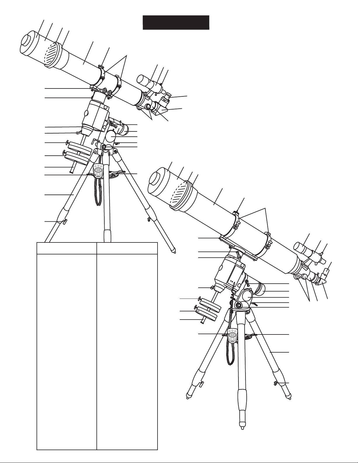
HEQ5
Dust Cap/Mask
A.
(Remove before Viewing)
Sun Shade/Dew Cap
B.
Objective Lens Location
C.
Adjustable Lens Cell
D.
Telescope Main Body
E.
Piggyback Bracket
F.
Tube Ring
G.
Finderscope
H.
Finderscope Bracket
I.
Alignment Screw
J.
Eyepiece
K.
Diagonal
L.
Focus Tube
M.
Focus Knob
N.
1.
R.A. Lock Lever
2.
Polarscope Holder
(not shown)
3.
Latitude Scale
4.
Altitude Adjustment T-bolts
5.
Azimuth Adjustment Knob
6.
Accessory T ray
7.
Height Adjustment
Clamp
8.
Tripod Leg
9.
Hand Control
10.
Counterweight Rod
11.
Counterweight
12.
Counterweight Thumb
Screw
13.
Counterweight Rod
Lock Knob
14.
Dec Setting Circle
15.
Dec Lock Lever
16.
Mounting Plate
EQ6
Dust Cap/Mask
A.
(Remove before Viewing)
Sun Shade/Dew Cap
B.
Objective Lens Location
C.
Adjustable Lens Cell
D.
Telescope Main Body
E.
Piggyback Bracket
F.
Tube Ring
G.
Finderscope
H.
Finderscope Bracket
I.
Alignment Screw
J.
Eyepiece
K.
Diagonal
L.
Focus Tube
M.
Focus Knob
N.
R.A. Lock Lever
1.
Polarscope Holder
2.
(not shown)
Latitude Scale
3.
Altitude Adjustment T-bolts
4.
Azimuth Adjustment Knob
5.
Accessory T ray
6.
Tripod Leg
7.
Height Adjustment
8.
Clamp
Hand Control
9.
Counterweight Rod
10.
Counterweight
11.
Counterweight Thumb
12.
Screw
Counterweight Rod
13.
Lock Knob
Dec Setting Circle
14.
Dec Lock Lever
15.
Mounting Plate
16.
12
11
10
16
15
14
13
F
G
H
I
J
K
1
2
3
4
N
5
SLOW
FAST
GUIDE
2
1
3
9
456
7
GO
SET
6
M
L
7
8
Page 3

16
15
14
13
12
11
10
A
B
C
D
HEQ5
REFRACTORREFRACTOR
E
F
G
H
I
J
K
L
N1
M
2
3
4
5
A
SLOW
FAST
GUIDE
2
1
3
456
7
GO
9
SET
6
B
C
D
EQ6
E
8
7
HEQ5
Dust Cap/Mask
A.
(Remove before Viewing)
Sun Shade/Dew Cap
B.
Objective Lens Location
C.
Adjustable Lens Cell
D.
Telescope Main Body
E.
Piggyback Bracket
F.
Tube Ring
G.
Finderscope
H.
Finderscope Bracket
I.
Alignment Screw
J.
Eyepiece
K.
Diagonal
L.
Focus Tube
M.
Focus Knob
N.
1.
R.A. Lock Lever
2.
Polarscope Holder
(not shown)
3.
Latitude Scale
4.
Altitude Adjustment T-bolts
5.
Azimuth Adjustment Knob
6.
Accessory T ray
7.
Height Adjustment
Clamp
8.
Tripod Leg
9.
Hand Control
10.
Counterweight Rod
11.
Counterweight
12.
Counterweight Thumb
Screw
13.
Counterweight Rod
Lock Knob
14.
Dec Setting Circle
15.
Dec Lock Lever
16.
Mounting Plate
EQ6
Dust Cap/Mask
A.
(Remove before Viewing)
Sun Shade/Dew Cap
B.
Objective Lens Location
C.
Adjustable Lens Cell
D.
Telescope Main Body
E.
Piggyback Bracket
F.
Tube Ring
G.
Finderscope
H.
Finderscope Bracket
I.
Alignment Screw
J.
Eyepiece
K.
Diagonal
L.
Focus Tube
M.
Focus Knob
N.
R.A. Lock Lever
1.
Polarscope Holder
2.
(not shown)
Latitude Scale
3.
Altitude Adjustment T-bolts
4.
Azimuth Adjustment Knob
5.
Accessory T ray
6.
Tripod Leg
7.
Height Adjustment
8.
Clamp
Hand Control
9.
Counterweight Rod
10.
Counterweight
11.
Counterweight Thumb
12.
Screw
Counterweight Rod
13.
Lock Knob
Dec Setting Circle
14.
Dec Lock Lever
15.
Mounting Plate
16.
12
11
10
16
15
14
13
F
G
H
I
J
K
1
2
3
4
N
5
SLOW
FAST
GUIDE
2
1
3
9
456
7
GO
SET
6
M
L
7
8
Page 4
E
REFLECTORREFLECTOR
F
G
H
I
HEQ5
J
D
K
L
C
B
A
16
EQ6
15
E
F
G
14
13
12
11
10
SLOW
FAST
GUIDE
2
1
3
456
7
GO
SET
9
1
2
D
3
4
C
5
H
I
J
K
B
6
7
A
16
L
15
14
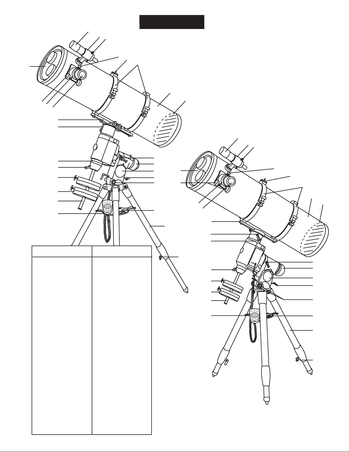
HEQ5
Eyepiece
A.
Focus Tube
B.
Focus Knob
C.
Dust Cap/Mask
D.
(Remove before viewing)
Finderscope
E.
Finderscope Bracket
F.
Alignment Screw
G.
Tension Adjustment Screw
H.
Piggyback Bracket
I.
Tube Rings
J.
Telescope Main Body
K.
Primary Mirror Location
L.
1.
R.A. Lock Lever
2.
Polarscope Holder
(not shown)
3.
Latitude Scale
4.
Altitude Adjustment T-bolts
5.
Azimuth Adjustment Knob
6.
Accessory T ray
7.
Tripod Leg
8.
Height Adjustment Clamp
9.
Hand Control
10.
Counterweight Rod
11.
Counterweight
12.
Counterweight Thumb
Screw
13.
Counterweight Rod
Lock Knob
14.
Dec Setting Circle
15.
Dec Lock Lever
16.
Mounting Plate
EQ6
Eyepiece
A.
Focus Tube
B.
Focus Knob
C.
Dust Cap/Mask
D.
(Remove before viewing)
Finderscope
E.
Finderscope Bracket
F.
Alignment Screw
G.
Tension Adjustment Screw
H.
Piggyback Bracket
I.
Tube Rings
J.
Telescope Main Body
K.
Primary Mirror Location
L.
R.A. Lock Lever
1.
Polarscope Holder
2.
(not shown)
Latitude Scale
3.
Altitude Adjustment T-bolts
4.
Azimuth Adjustment Knob
5.
Accessory T ray
6.
Tripod Leg
7.
Height Adjustment Clamp
8.
Hand Control
9.
Counterweight Rod
10.
Counterweight
11.
Counterweight Thumb
12.
Screw
Counterweight Rod
13.
Lock Knob
Dec Setting Circle
14.
Dec Lock Lever
15.
Mounting Plate
16.
8
1
13
12
2
3
4
11
10
SLOW
FAST
GUIDE
2
1
3
456
9
7
GO
SET
5
6
7
8
Page 5
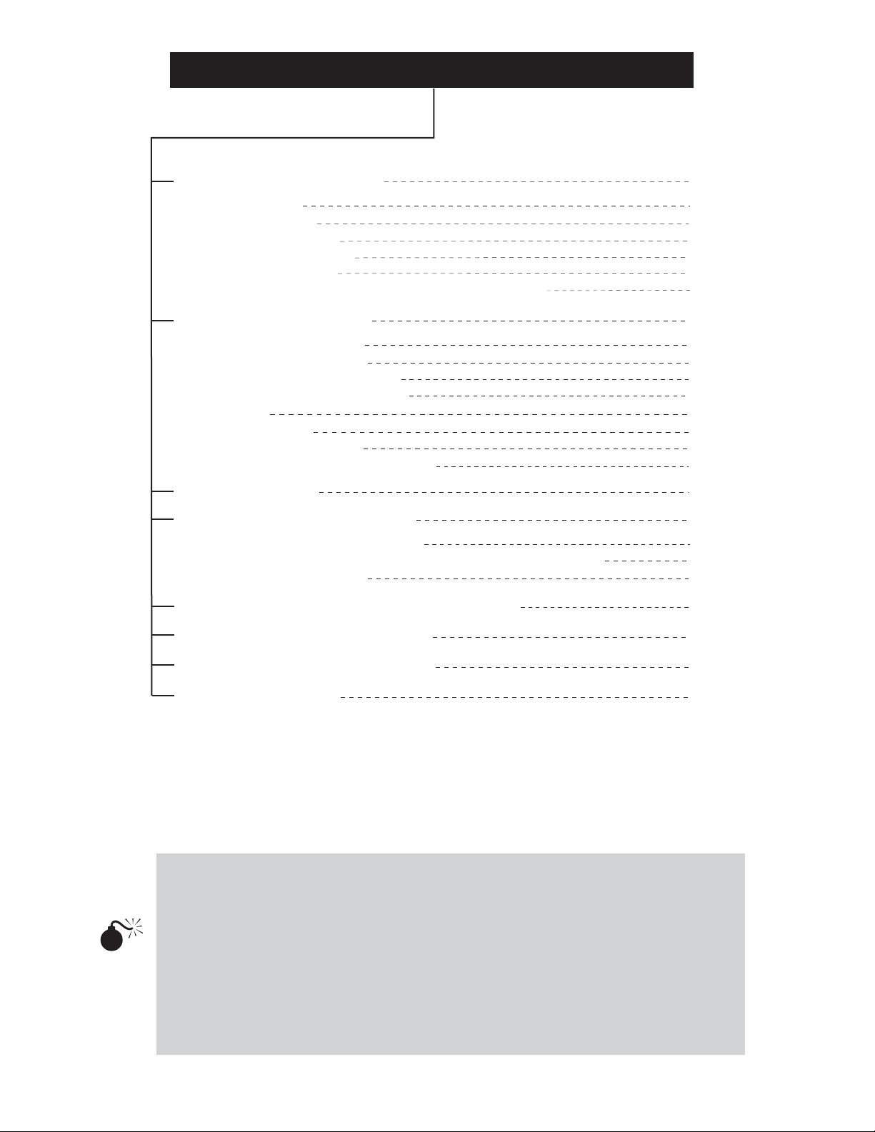
TABLE OF CONTENTS
ASSEMBLING YOUR TELESCOPE
Tripod Set Up
Mount Assembly
T elescope Assembly
Finderscope Assembly
Eyepiece Assembly
Hand Control Holder Installation (For SynScanTM Only)
OPERATING YOUR TELESCOPE
Aligning the Finderscope
Balancing the Telescope
Operating the Mount Manually
Using the Optional Barlow Lens
Focusing
Polar Alignment
Pointing Your Telescope
Choosing the Appropriate Eyepiece
OBSERVING THE SKY
PROPER CARE FOR YOUR TELESCOPE
Collimating a Newtonian Reflector
Collimating a Refractor with the Adjustable Objective-Lens Cell
Cleaning Your Telescope
5
5
5
6
6
7
7
8
8
8
9
10
10
10
14
17
18
19
19
21
21
APPENDIX A - STANDARD TIME ZONES OF THE WORLD
APPENDIX B - OPTIONAL ACCESSORIES
APPENDIX C - RECOMMENDED READING
APPENDIX D - GLOSSARY
I
II
IV
V
NEVER USE YOUR TELESCOPE TO LOOK DIRECTLY AT THE SUN.
PERMANENT EYE DAMAGE WILL RESULT. USE A PROPER SOLAR FILTER
FIRMLY MOUNTED ON THE FRONT OF THE TELESCOPE FOR VIEWING
THE SUN. WHEN OBSERVING THE SUN, PLACE A DUST CAP OVER YOUR
FINDERSCOPE OR REMOVE IT TO PROTECT YOU FROM ACCIDENTAL
EXPOSURE. NEVER USE AN EYEPIECE-TYPE SOLAR FILTER AND NEVER
USE YOUR TELESCOPE TO PROJECT SUNLIGHT ONTO ANOTHER
SURFACE, THE INTERNAL HEAT BUILD-UP WILL DAMAGE THE
TELESCOPE OPTICAL ELEMENTS.
Page 6
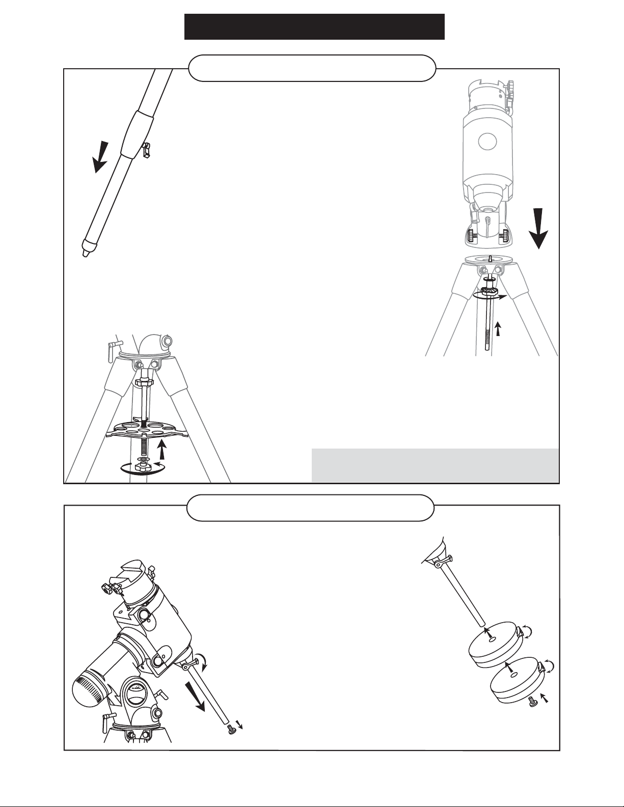
Fig. 1
Fig. 3
ASSEMBLING YOUR TELESCOPE
TRIPOD SET UP
ASSEMBLING THE TRIPOD LEGS (Fig.1)
1) Slowly loosen the height adjustment clamp
and gently pull out the lower section of
each tripod leg. Tighten the clamps to hold
the legs in place.
2) Spread the tripod legs apart to stand
the tripod upright.
3) Place a carpenter's level or bubble level on
the top of the tripod legs. Adjust the height of
each tripod leg until the tripod head is properly
leveled. Note that the tripod legs may not be at
same length when the equatorial mount is level.
ATTACHING MOUNT TO TRIPOD LEGS (Fig. 2)
1) Align metal dowel on the tripod head with the gap
between the azimuth adjustment knobs underneath
the mount.
2) Push the primary locking shaft up against the
mount and turn the knurled knob underneath to
secure mount to tripod.
Fig. 2.
EQ-6
Fig. 4
ATTACHING THE ACCESSORY TRAY (Fig. 3)
1) Slide the accessory tray along the primary locking
shaft until it pushes against the tripod legs.
2) Secure with the washer and locking knob.
Note: Loosen the azimuth adjustment knobs if mount does not
fit into tripod head completely. Retighten knobs to secure.
MOUNT ASSEMBLY
INST ALLING THE COUNTERWEIGHTS (Fig. 4, 5)
1) Loosen the counterweight rod lock knob
and gently pull out the counterweight rod.
Re-tighten the lock knob to secure the
counterweight rod in place.
2) Unscrew the threaded cap from the
end of the counterweight rod.
3) Locate the counterweights and slide them
halfway along the counterweight rod. Tighten
the counterweight thumb screws to secure.
5) Replace the cap on the end of the
counterweight rod.
Fig. 5
(diagram applicable to both mounts)
5
Page 7
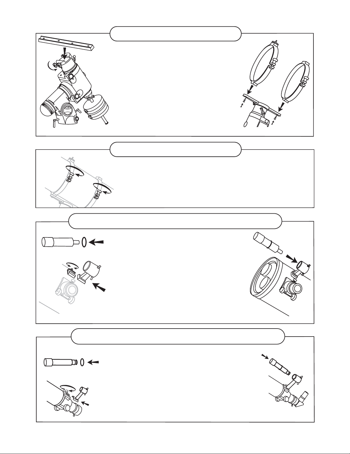
Fig. 6
EQ-6
(diagram applicable to both mounts)
TELESCOPE ASSEMBLY
Fig. 7
ATTACHING THE MOUNTING PLATE (Fig.6)
1) Position the mounting plate on the mounting bracket.
2) Secure by tightening the two locking screws.
A TT ACHING THE TUBE RINGS (Fig.7)
1) Remove the telescope tube assembly from
its plastic packaging.
2) Remove the tube rings from the telescope by
releasing their thumb nuts and opening
their hinges.
3) Using the bolts provided, fasten the tube rings
to the mount with the 10mm wrench provided.
TELESCOPE ASSEMBLY
Fig.9
Fig.10
Fig. 8
A TT ACHING THE TELESCOPE MAIN TUBE TO THE
TUBE RINGS (Fig.8)
1) Remove the telescope tube from the paper covering.
2) Find the center of balance of the telescope tube. Place this in
between the two tube rings. Close the hinges around the
telescope and fasten securely by tightening the thumb nuts.
FINDERSCOPE ASSEMBLY (for reflectors)
A TT ACHING THE FINDERSCOPE
BRACKET (Fig. 9,10,11)
1) Locate the finderscope bracket. Carefully remove
the rubber-o-ring from the finderscope bracket.
2) Position the o-ring into the groove located
approximately half-way along the finderscope tube.
3) Locate the finderscope optical assembly.
4) Slide the finderscope bracket into the rectangular
slot and tighten the screw to hold the mount in place.
5) Position the finderscope into its bracket by sliding
it backwards until the rubber o-ring seats in the
finderscope mount.
Fig.11
Fig.12
Fig.13
FINDERSCOPE ASSEMBLY (for refractors)
A TT ACHING THE FINDERSCOPE (Fig.12,13,14)
1) Locate the finderscope bracket. Carefully remove
the rubber-o-ring from the finderscope bracket.
2) Position the o-ring into the groove located approximately
half-way along the finderscope tube.
3) Locate the finderscope optical assembly.
4) Slide the finderscope bracket into the rectangular slot and
tighten the screw to hold the mount in place.
5) Position the finderscope into its mount by sliding it backwards
until the rubber o-ring seats in the finderscope mount.
6
Fig.14
Page 8
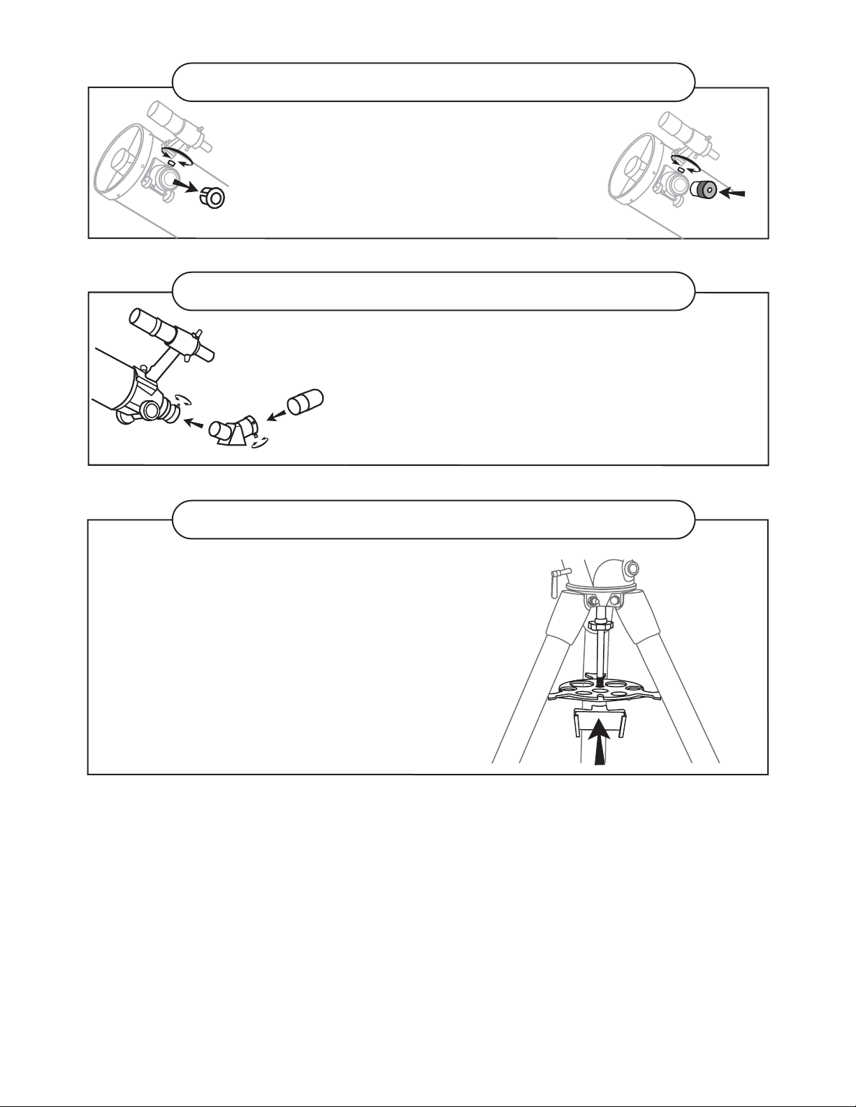
EYEPIECE ASSEMBLY (for reflectors)
Fig.15
Fig.16
INSERTING THE EYEPIECE (Fig.15, 16)
1) Unscrew the thumbscrews on the end of the focus
tube to remove the black plastic end-cap.
2) Insert the desired eyepiece and secure it by
retightening the thumbscrews.
EYEPIECE ASSEMBLY (for refractors)
Fig.17
INSERTING THE EYEPIECE (Fig.17)
1) Loosen the thumbscrew on the end of the focus tube.
2) Insert the diagonal into the focus tube and re-tighten
the thumbscrew to hold the diagonal in place.
3) Loosen the thumbscrews on the diagonal.
4) Insert the desired eyepiece into diagonal and secure
by re-tightening the thumbscrews.
HAND CONTROL HOLDER INSTALLATION
INSTALLING THE HAND CONTROL
HOLDER (Fig.18)
Locate the hand control holder. Slide
the holder onto the accessory tray as
shown in Fig.6.
(for SynScanTM only)
Fig.18
7
Page 9
OPERATING YOUR TELESCOPE
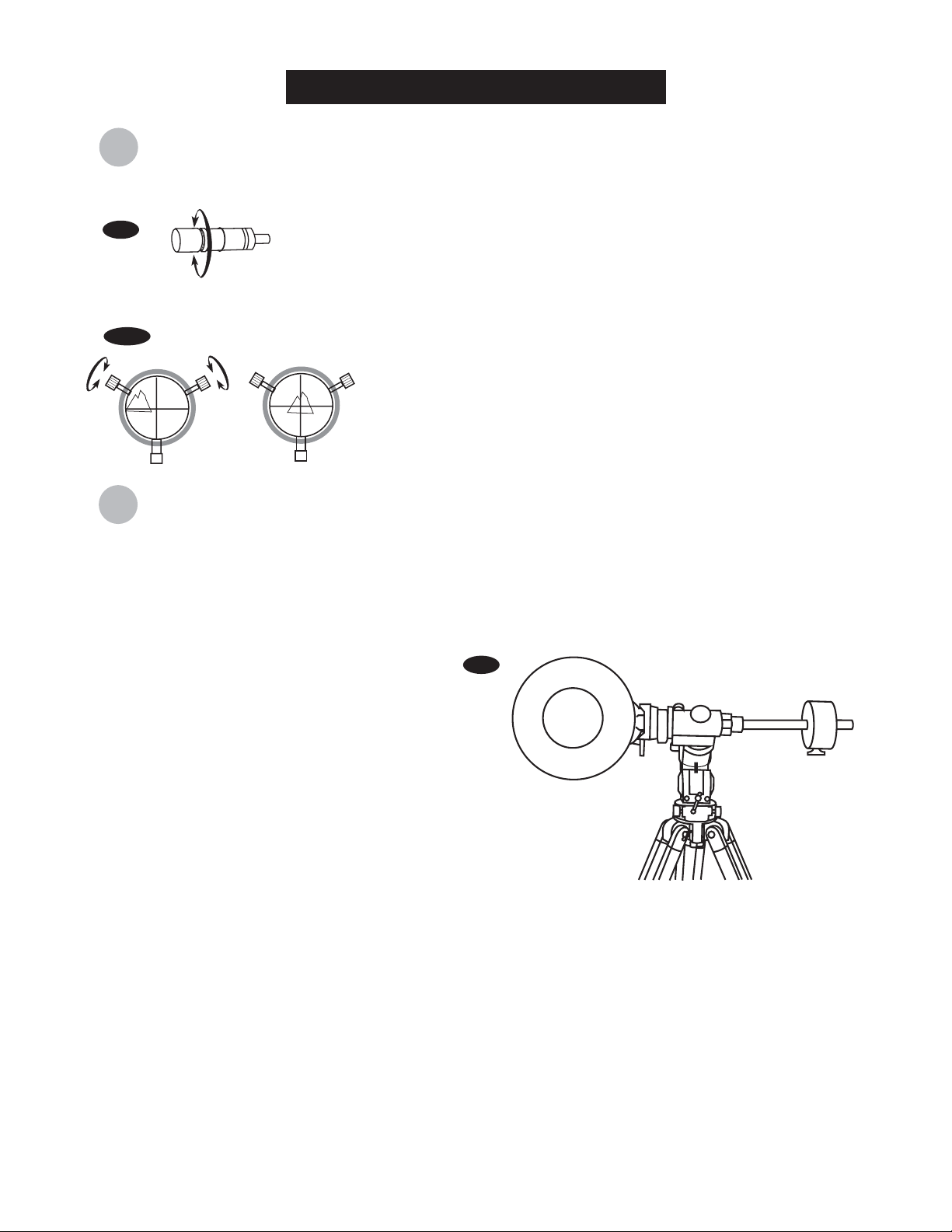
ligning the finderscope
A
Fig.a
Fig.a-1
alancing the telescope
B
These fixed magnification scopes mounted on the optical tube are very useful
accessories. When they are correctly aligned with the telescope, objects can
be quickly located and brought to the centre of the field. Alignment is best
done outdoors in day light when it's easier to locate objects. If it is necessary
to refocus your finderscope, sight on an object that is at least 500 yards
(metres) away. Loosen the locking ring by unscrewing it back towards the
bracket. The front lens holder can now be turned in and out to focus. When
focus is reached, lock it in position with the locking ring (Fig.a).
1)
Choose a distant object that is at least 500 yards away and
point the main telescope at the object. Adjust the telescope so
that the object is in the centre of the view in your eyepiece.
2)
Check the finderscope to see if the object centred in the main
telescope view is centred on the crosshairs.
3)
Adjust the two small screws to centre the finderscope
crosshairs on the object (Fig.a-1).
A Telescope should be balanced before each observing session. Balancing reduces stress on the telescope
mount and allows for precise control of micro-adjustment. A balanced telescope is specially critical when
using the optional clock drive for astrophotography. The telescope should be balanced after all accessories
(eyepiece, camera, etc.) have been attached. Before balancing your telescope, make sure that your tripod is
balanced and on a stable surface. For photography, point the telescope in the direction you will be taking
photos before performing the balancing steps.
Fig.b
R.A. Balancing
Slowly unlock the R.A. and Dec. lock knobs.
1)
Rotate the telescope until both the optical tube
and the counterweight rod are horizontal to the
ground, and the telescope tube is to the side of
the mount (Fig.b).
Tighten the Dec. lock knob.
2)
Move the counterweights along the counterweight
3)
rod until the telescope is balanced and remains
stationary when released.
Tighten the counterweight thumb screws to hold
4)
the counterweights in their new position.
Dec. Balancing
The R.A. balancing should be done before proceeding with Dec. balancing.
For best results, adjust the altitude of the mount to between 60º and 75º if possible.
1)
Release the R.A. lock knob and rotate around the R.A. axis so that the counterweight rod is in a horizontal
2)
position. Tighten the R.A. lock knob.
Unlock the Dec. lock knob and rotate the telescope tube until it is parallel to the ground.
3)
Slowly release the telescope and determine in which direction it rotates. Loosen the telescope tube rings and
4)
slide the telescope tube forward or backward in the rings until it is balanced.
Once the telescope no longer rotates from its parallel starting position, re-tighten the tube rings and the Dec.
5)
lock knob. Reset the altitude axis to your local latitude.
(diagram applicable to both mounts)
N
8
Page 10

perating the mount manually
O
The HEQ5 and EQ6 mount have controls for
both conventional altitude (up-down) and
azimuthal (left-right) directions of motion. Use
the altitude adjustment T-bolts for altitude
adjustments. These allow fine-adjustment for
setting the mount to your local latitude. The
azimuthal axis is changed by the two azimuth
adjustment knobs located near the tripod head.
These allow fine-adjustment of azimuth for polar
aligning (Fig.c).
Make sure to loosen one altitude
adjustment T-bolt before tightening the
other. Over-tightening can cause the bolts
to bend or break.
In addition, the HEQ5 and EQ6 mounts have
direction controls for polar aligned astronomical
observing. These directions use right ascension
(east/west) and declination (north/south) axis.
There are two options to move the telescope in
these directions: For large and quick movement,
loosen the R.A. lock level under the R.A. shaft
or the Dec. lock level near the top of the mount
(Fig.d). For fine adjustments, use the SynTrekTM
or SynScanTM hand control.
Fig.c
Altitude
adjustment
EQ-6
Azimuth
adjustment
(Diagram applicable to both mounts)
Fig.d
OFF
ON
Power
DC 12V
(Diagram applicable to both mounts)
Dec. adjustment
R.A. adjustment
There are three numerical scales on this mount.
The lower scale is used for polar alignment of
the telescope to your local latitude. The R.A.
(right ascension) scale is measures hour angle
and is adjustable to your local meridian. The
declination scale is located near the top of the
mount (Fig.e).
(For SynScanTM Only) Do not adjust the mount
manually when under the SynScanTM operation
mode. The telescope will have to be returned to
the Home Position and initial star alignment will
have to be done again.
Warning
Tips
Trouble Shooting
Fig.e
HEQ5
EQ6
Dec. scale
R.A. scale
Latitude
scale
Dec. scale
OFF
ON
Power
DC 12V
R.A. scale
Latitude
scale
9
Page 11

sing the optional Barlow lens
U
A Barlow is a negative lens which increases the
magnifying power of an eyepiece, while reducing the field
of view. It expands the cone of the focussed light before it
reaches the focal point, so that the telescope's focal length
appears longer to the eyepiece.
Fig.f
Eyepiece
Barlow
Diagonal
The Barlow is inserted between the focuser and the
eyepiece in a reflector, and usually between the diagonal
and the eyepiece in a refractor or a maksutov (Fig.f). With
some telescopes, it can also be inserted between the
focuser and the diagonal, and in this position it gives even
greater magnification. For example, a 2X Barlow when
inserted after the diagonal can become 3X when placed in
front of the diagonal.
In addition to increasing magnification, the benefits of
using a Barlow lens include improved eye relief, and
reduced spherical aberration in the eyepiece. For this
reason, a Barlow plus a lens often outperform a single lens
producing the same magnification. However, its greatest
value may be that a Barlow can potentially double the
number of eyepieces in your collection.
ocusing
F
Slowly turn the focus knobs under the focuser, one way or
the other, until the image in the eyepiece is sharp (Fig.g).
The image usually has to be finely refocused over time,
due to small variations caused by temperature changes,
flexures, etc. This often happens with short focal ratio
telescopes, particularly when they have not yet reached
outside temperature. Refocusing is almost always
necessary when you change an eyepiece or add or
remove a Barlow lens. On some focusers, there is a
tension adjustment. Over-tighten this may damage the
rack and pinion assembly.
(Refracting Telescopes
and Maksutovs)
(Reflecting Telescopes)
Fig.g
(Refracting Telescopes)
Barlow
Eyepiece
(Reflecting Telescopes)
olar Alignment
P
Preparing the Mount
This section describes how to achieve a precise polar
alignment with your HEQ5/EQ6 mount. To achieve a
precise polar alignment it is first necessary to prepare the
mount. In the Northern Hemisphere, this includes orienting
the polar scope reticule and aligning the polar scope
reticule. If you are in the Southern Hemisphere, you only
need to align the polar scope reticule. These steps, which
only need to be done once, are outlined first.
If you have already prepared your mount then you can
skip to the final section entitled "Procedure for Precise
Polar Alignment of the HEQ5/EQ6 Mount". If not, follow
the steps to prepare your mount for precise polar
alignment.
10
Fig.h
(Maksutov Telescopes)
off
on
Power
(Diagram applicable to both mounts)
Page 12

First, remove the caps from the upper and lower ends of the RA axis so you can look into the polar
scope (Fig.h). Release the counterweight shaft and rotate the mount in declination axis so that the
hole in the shaft is in front of the polar scope. This allows you to see all the way through the RA shaft.
Fig.h-1
GLOSSARY (Fig.h-1)
Date Scale Indicator
This indicator is used as a reference
HEQ5
Setscrew
point when using the Date Scale.
Date Scale
The circular scale surrounding the
polar scope eyepiece. On the outer
part of the scale you will see months
from 1 (January) to 12 (December)
with divisions in between them. The
longer divisions mark 10-day
increments and the short ones 2-day
increments. The number of the
month appears below the 15th day
of that month.
Longitude Scale
The small scale that appears below
the Date Scale and is labeled E 20
10 0 10 20 W. Since the Date and
Longitude scales are on the same
ring, This ring is sometimes referred
to as the Date/Longitude scale.
Longitude Index Marker
A small line on the black plastic ring
that is next to the Date/Longitude
Ring.
Index Marker Ring
The small black ring with the Index
marker on it.
RA Setting Circle
The scale showing hours from 0 to
23. On the HEQ5 it is directly above
the Date/Longitude Scale. On the
EQ6 it is opposite the end where the
polar scope eyepiece is located. If
you live in the Northern Hemisphere
you will be using the upper scale on
the RA Setting Circle. The lower
scale is for use in the Southern
Hemisphere.
Date Scale and RA
23
22
1
21
2
3
20
4
12
20
E
1
0
0
10
2
23
1
0
10
20
W
Setting Indicator
4
RA Setting
Circle
Date scale (upper)
Longitude Scale
(lower)
Index Marker
Ring
Longitude Index
Marker
EQ6
Date Scale
Indicator
Date scale (upper)
Longitude Scale
(lower)
Index Marker
Ring
Longitude Index
Marker
RA Setting Indicator
On the HEQ5 the Date Scale
Indicator also acts as the RA Setting
indicator. On the EQ6, it is the small
triangular indicator next to the RA
setting circle.
RA Setting Indicator
11
Page 13

Step 1: Orienting the Polar Scope Reticule
Follow the steps as outlined below to properly orient the reticule inside the polar scope.
1.
Unlock the RA axis and rotate it until the reticule pattern shows the Polaris Location Indicator at the
very bottom (i.e., the 6 o'clock position - See Figure h-2). Re-lock the RA axis.
2.
Loosen the RA setting circle by loosening the setscrews, then turn the setting circle so that its
indicator is pointing to zero. Do not rotate the mount in RA, just loosen and move the RA Setting
Circle. When done, tighten the setscrews.
3.
Now unlock the RA axis and rotate the mount so the Setting Circle indicator points to 1 h 0 m. Use
the top scale if you are in the northern hemisphere and the bottom scale if you are in the southern
hemisphere. Lock the RA axis.
Rotate your Date/Longitude scale so that October 10 lines
4.
up with the Date Scale Indicator (i.e., 10th day of month
10).
Unlock the RA axis and rotate it back so the RA Setting
5.
Indicator points to zero again on the RA Setting Circle
scale.
Use small flat head screw driver to loosen the setscrew on
6.
the Index Marker Ring. Rotate the ring so that the marker
is aligned with October 10 on the datescale. Tighten the
setscrew to lock the ring in place.
After completing these steps you will have the reticule in the
proper orientation.
Fig.h-2
C
a
s
s
i
o
p
e
i
a
NCP
Octans
Polaris
p
p
i
D
g
i
B
r
e
Step 2: Aligning the Polar Scope Reticule
The polar scope needs to be aligned with the polar axis of your mount. The steps below tell you how to
perform this alignment. Note, you can do this procedure at night while pointing at Polaris. However, it is
probably easier to do it in the daytime using a distant point as your target (e.g, a street light a couple of
hundred yards away). If doing the procedure during the day, you might find it convenient to set your
altitude to near parallel with the ground to put the eyepiece of the polar scope into a comfortable
position. Just be sure to leave room to make vertical adjustments in both directions. Also, do this
procedure without an OT A or counterweights. It will make turning the mount a lot simpler.
1.
Locate a distant object and place it under the cross at the centre of the polarscope reticule.
Rotate the mount in RA 180 degrees (i.e., 12 hours on the RA
2
setting circle).
Note the displacement of your target from the centre of the
3.
crosshairs. If it is not displaced at all, it means your polar
scope reticule is already properly aligned and you don't need
to do any more. If it is displaced, continue with the next step
of the alignment procedure.
Use the three adjustment screws on the polar scope to move
4.
the reticule so that exactly one-half of the displacement is
corrected for. For example, if the displacement were about
half an inch in the direction of 1 o'clock, then you would adjust
the cross at the centre of the reticule to go half the distance in
that direction (See Figure h-3).
Fig.h-3
If target drifted to here
Now continue to move the cross using the altitude and
5.
azimuth adjusters on the mount. When the target is back
under the cross, go back to step 2, but this time rotate the
mount 180 degrees in the opposite direction. If you still get
displacement of the target, repeat steps 3-5.
12
adjust reticule to
place it here (half
the distance)
Page 14

Procedure for Precise Polar Alignment of the HEQ5/EQ6 Mount.
Preliminary Step: Determining the Zero Point on the Longitude Scale
The alignment procedure requires that you set the Longitude scale to "Zero". Depending on where you
live, "Zero" can be anyplace between the E and the W on longitude scale, so first you need to determine
where zero is for your location. Your Zero point is equal to the difference between your actual longitude
and the longitude of the central meridian of your time zone. To calculate the longitude of your central
meridian, multiply your time zone offset from Greenwich Mean T ime (GMT) by 15.
For example, in Waterloo, Ontario, Canada (Eastern Time) the time zone offset is -5 hours. Ignore the
sign and simply multiply 5 x 15 = 75. The longitude of the central meridian for the Eastern Time Zone is
75 degrees west. The actual longitude at the viewing location in Waterloo is 80 degrees 30 minutes
West. Ignore the 30 minutes and just use 80 in the equation.
Now it's simple, 80-75=5. Since 80 is greater than 75 the result
is positive 5. That means Waterloo, Ontario is west of its
Fig.h-4
HEQ5
Central Meridian. In this case, the zero point is at the "5" mark
on the W side of the scale. If the location was east of its central
meridian the equation would yield a negative value. In that case
the E side of the scale should be used.
23
22
1
21
2
3
20
4
12
20
E
1
0
0
10
2
23
1
10
20
W
4
0
Precise Polar Alignment for the Northern Hemisphere:
Rotate the RA axis so the Longitude Index Marker (See
1.
Figure h-4) lines up with your Date Scale Indicator. Lock the
RA axis.
Turn the Date/Longitude scale so that your calculated "Zero"
2
point lines up with the Longitude Index Marker.
Unlock the RA axis and rotate the mount so the Date Scale
3
Indicator is pointing at the current date. Lock the RA axis.
Loosen and move the RA Setting Circle to show the current
4
time. Use the upper portion of the scale for the Northern
Hemisphere and the bottom for the Southern hemisphere.
Tighten the Setting Circle.
Unlock the RA axis and rotate the mount until RA setting circle
5
indicator points at Zero. The reticule is now in the proper
orientation.
Use the altitude and azimuth adjusters to place Polaris into
6
the small circle on the perimeter of the bigger circle in the
polar scope reticule.
The polar alignment is complete. This procedure should get you
within a couple of minutes of true north.
Precise Polar Alignment for the Southern Hemisphere:
There is a 4-star pattern in the polar scope, which resembles the
bucket of the big Dipper. In the Southern Hemisphere, there is an
Asterism in Octans which can be used for Polar Alignment. This
procedure can be somewhat difficult in the city because all four
of the stars in the Asterism are fainter than Magnitude 5.
Rotate the telescope in RA axis and/or use the altitude and
azimuth adjusters to place the four stars in the Asterism in the
four circles (Fig. h-5).
EQ6
Fig.h-5
B
i
g
Place the four stars
in the Asterism here
a
i
ans
Oct
aris
Pol
D
i
p
p
e
r
NCP
e
p
o
i
s
s
a
C
13
Page 15

ointing your telescope
P
A German Equatorial mount has an adjustment, sometimes called a wedge, which tilts the mount's polar axis
so that it points at the appropriate Celestial Pole (NCP or SCP). Once the mount has been polar aligned, it
needs to be rotated around only the polar axis to keep an object centred. Do not reposition the mount base or
change the latitude setting. The mount has already been correctly aligned for your geographical location (ie.
Latitude), and all remaining telescope pointing is done by rotating the optical tube around the polar (R.A.) and
declination axes.
A problem for many beginners is recognizing that a polar-aligned equatorial mount acts like an alt-azimuth
mount which has been aligned to a celestial pole. The wedge tilts the mount to an angle equal to the
observer's Latitude, and therefore it swivels around a plane which parallels the celestial (and Earth's) equator
(Fig.i). This is now its "horizon"; but remember that part of the new horizon is usually blocked by the Earth.
This new "azimuth" motion is called Right Ascension (R.A). In addition, the mount swivels North(+) and South() from the Celestial Equator towards the celestial poles. This plus or minus "altitude" from the celestial equator
is called Declination (Dec).
Right
Ascension
Meridian
Line
Fig.i
Equatorial Mount
(Northern Hemisphere)
Zenith
Mount aligned on
North Celestial Pole
Object you
are viewing
Polaris
Declination
Latitude
W
N
S
Plane of local horizon
Nadir
14
E
Apparent
movement
of stars
Plane of Celestial
Equator
Page 16

Fig.i-1
Fig.i-2
a.
Celestial Pole
+
b.
Celestial
Pole
+
c.
Pointing to the NCP
For the following examples, it is
assumed that the observing site is
in the Northern Hemisphere. In the
first case (Fig.i-1b), the optical tube
is pointing to the NCP. This is its
probable position following the
polar-alignment step. Since the
telescope is pointing parallel to the
polar axis, it still points to the NCP
as it is rotated around that axis
counter-clockwise, (Fig.i-1a) or
clockwise (Fig.i-1c).
Pointing toward the western or
eastern horizon
Now, consider pointing the
telescope to the western (Fig.i-2a)
or eastern (Fig.i-2b) horizon. If the
counterweight is pointing North,
the telescope can be swivelled from
one horizon to the other around the
Dec axis in an arc that passes
through the NCP (any Dec arc will
pass through the NCP if the mount
is polar-aligned). It can be seen
then that if the optical tube needs to
be pointed at an object north or
south of this arc, it has to be also
rotated around the R.A axis.
a.
b.
Telescope pointing East
Counterweight pointing North
(These diagrams applicable to HEQ5 and EQ6 mounts)
Rotation of the R.A. axis
Rotation of the Dec. axis
Telescope pointing West
Counterweight pointing North
15
Page 17

Telescopes with long focal lengths often
have a "blind spot" when pointing near
the zenith, because the eyepiece-end of
the optical tube bumps into the mount's
legs (Fig.i-3a). To adapt for this, the
optical tube can be very carefully slipped
up inside the tube rings (Fig.i-3b). This
can be done safely because the tube is
pointing almost vertically, and therefore
moving it does not cause a Dec-balance
problem. It is very important to move the
tube back to the Dec-balanced position
before observing other sky areas.
Something which can be a problem is that
the optical tube often rotates so that the
eyepiece, finderscope and the focussing
knobs are in less convenient positions.
The diagonal can be rotated to adjust the
eyepiece. However, to adjust the
positions of the finderscope and focussing
knobs, loosen the tube rings holding the
optical tube and gently rotate it. Do this
when you are going to view an area for
while, but it is inconvenient to do every
time you briefly go to a new area.
Fig.i-3
a.
b.
Finally, there are a few things to consider
to ensure that you are comfortable during
the viewing session. First is setting the
height of the mount above the ground by
adjusting the tripod legs. You must
consider the height that you want your
eyepiece to be, and if possible plan on
sitting on a comfortable chair or stool.
Very long optical tubes need to be
mounted higher or you will end up
crouching or lying on the ground when
looking at objects near the zenith. On the
other hand, a short optical tube can be
mounted lower so that there is less
movement due to vibration sources, such
as wind. This is something that should be
decided before going through the effort of
polar aligning the mount.
Telescope pointing at the Zenith
16
Page 18

hoosing the appropriate eyepiece
C
Calculating the magnification (power)
The magnification produced by a telescope is determined by the focal length of the eyepiece that is used with
it. To determine a magnification for your telescope, divide its focal length by the focal length of the eyepieces
you are going to use. For example, a 10mm focal length eyepiece will give 80X magnification with an 800mm
focal length telescope.
Focal length of the telescope
magnification =
When you are looking at astronomical objects, you are looking through a column of air that reaches to the
edge of space and that column seldom stays still. Similarly, when viewing over land you are often looking
through heat waves radiating from the ground, house, buildings, etc. Your telescope may be able to give very
high magnification but what you end up magnifying is all the turbulence between the telescope and the
subject. A good rule of thumb is that the usable magnification of a telescope is about 2X per mm of aperture
under good conditions.
Calculating the field of view
The size of the view that you see through your telescope is called the true (or actual) field of view and it is
determined by the design of the eyepiece. Every eyepiece has a value, called the apparent field of view, which
is supplied by the manufacturer. Field of view is usually measured in degrees and/or arc-minutes (there are 60
arc-minutes in a degree). The true field of view produced by your telescope is calculated by dividing the
eyepiece's apparent field of view by the magnification that you previously calculated for the combination.
Using the figures in the previous magnification example, if your 10mm eyepiece has an apparent field of view
of 52 degrees, then the true field of view is 0.65 degrees or 39 arc-minutes.
True Field of View =
To put this in perspective, the moon is about 0.5° or 30 arc-minutes in diameter, so this combination would be
fine for viewing the whole moon with a little room to spare. Remember, too much magnification and too small
a field of view can make it very hard to find things. It is usually best to start at a lower magnification with its
wider field and then increase the magnification when you have found what you are looking for. First find the
moon then look at the shadows in the craters!
Focal length of the eyepiece
Apparent Field of View
=
Magnification
=
800mm
10mm
52°
80X
=
= 80X
0.65°
Calculating the exit pupil
The Exit Pupil is the diameter (in mm) of the narrowest point of the cone of light leaving your telescope.
Knowing this value for a telescope-eyepiece combination tells you whether your eye is receiving all of the light
that your primary lens or mirror is providing. The average person has a fully dilated pupil diameter of about
7mm. This value, varies a bit from person to person, is less until your eyes become fully dark adapted and
decreases as you get older. To determine an exit pupil, you divide the diameter of the primary of your
telescope (in mm) by the magnification.
Diameter of Primary mirror in mm
Exit Pupil =
For example, a 200mm f/5 telescope with a 40mm eyepiece produces a magnification of 25x and an exit pupil
of 8mm. This combination can probably be used by a young person but would not be of much value to a
senior. The same telescope used with a 32mm eyepiece gives a magnification of about 31x and an exit pupil
of 6.4mm which should be fine for most dark adapted eyes. In contrast, a 200mm f/10 telescope with the
40mm eyepiece gives a magnification of 50x and an exit pupil of 4mm, which is fine for everyone.
Magnification
17
Page 19

OBSERVING THE SKY
ky conditions
S
Sky conditions are usually defined by two atmospheric characteristics, seeing, or the steadiness of the air,
and transparency, light scattering due to the amount of water vapour and particulate material in the air. When
you observe the Moon and the planets, and they appear as though water is running over them, you probably
have bad "seeing" because you are observing through turbulent air. In conditions of good "seeing", the stars
appear steady, without twinkling, when you look at them with unassisted eyes (without a telescope). Ideal
"transparency" is when the sky is inky black and the air is unpolluted.
electing an observing site
S
Travel to the best site that is reasonably accessible. It should be away from city lights, and upwind from any
source of air pollution. Always choose as high an elevation as possible; this will get you above some of the
lights and pollution and will ensure that you aren't in any ground fog. Sometimes low fog banks help to block
light pollution if you get above them. Try to have a dark, unobstructed view of the horizon, especially the
southern horizon if you are in the Northern Hemisphere and vice versa. However, remember that the darkest
sky is usually at the "Zenith", directly above your head. It is the shortest path through the atmosphere. Do not
try to observe any object when the light path passes near any protrusion on the ground. Even extremely light
winds can cause major air turbulence as they flow over the top of a building or wall.
Observing through a window is not recommended because the window glass will distort images considerably.
And an open window can be even worse, because warmer indoor air will escape out the window, causing
turbulence which also affects images. Astronomy is an outdoor activity.
hoosing the best time to observe
C
The best conditions will have still air, and obviously, a clear view of the sky. It is not necessary that the sky be
cloud-free. Often broken cloud conditions provide excellent seeing. Do not view immediately after sunset. After
the sun goes down, the Earth is still cooling, causing air turbulence. As the night goes on, not only will seeing
improve, but air pollution and ground lights will often diminish. Some of the best observing time is often in the
early morning hours. Objects are best observed as they cross the meridian, which is an imaginary line that runs
through the Zenith, due North-South. This is the point at which objects reach their highest points in the sky.
Observing at this time reduces bad atmospheric effects. When observing near the horizon, you look through
lots of atmosphere, complete with turbulence, dust particles and increased light pollution.
ooling the telescope
C
Telescopes require time to cool down to outside air temperature. This may take longer if there is a big
difference between the temperature of the telescope and the outside air. This minimizes heat wave distortion
inside telescope tube (tube currents). A rule of thumb is to allow 5 minutes per inch of aperture. For example,
a 4 inch refractor would require at least 20 minutes, but an 8" reflector would require at least 40 minutes to
cool off to outside conditions. Tip: use this time for polar alignment.
dapting your eyes
A
Do not expose your eyes to anything except red light for 30 minutes prior to observing. This allows your
pupils to expand to their maximum diameter and build up the levels of optical pigments, which are rapidly lost
if exposed to bright light. It is important to observe with both eyes open. This avoids fatigue at the eyepiece. If
you find this too distracting, cover the non-used eye with your hand or an eye patch. Use averted vision on
faint objects: The center of your eye is the least sensitive to low light levels. When viewing a faint object, don't
look directly at it. Instead, look slightly to the side, and the object will appear brighter.
18
Page 20

PROPER CARE FOR YOUR TELESCOPE
ollimating a Newtonian reflector
C
Collimation is the process of aligning the mirrors of your
telescope so that they work in concert with each other to
deliver properly focused light to your eyepiece. By
observing out-of-focus star images, you can test
whether your telescope's optics are aligned. Place a star
in the centre of the field of view and move the focuser so
that the image is slightly out of focus. If the seeing
conditions are good, you will see a central circle of light
(the Airy disc) surrounded by a number of diffraction
rings. If the rings are symmetrical about the Airy disc, the
telescope's optics are correctly collimated (Fig.j).
If you do not have a collimating tool, we suggest
that you make a "collimating cap" out of a plastic
35mm film canister (black with gray lid). Drill or
punch a small pinhole in the exact center of the lid
and cut off the bottom of the canister. This device
will keep your eye centered of the focuser tube.
Insert the collimating cap into the focuser in place
of a regular eyepiece.
Fig.j
Correctly aligned
Fig.j-1
Primary mirror
Fig.j-2
Needs collimation
Focuser
Support for
secondary mirror
Secondary mirror
Primary
mirror
Collimation is a painless process and works like this:
Pull off the lens cap which covers the front of the
telescope and look down the optical tube. At the bottom
you will see the primary mirror held in place by three
clips 120º apart, and at the top the small oval
secondary mirror held in a support and tilted 45º toward
the focuser outside the tube wall (Fig.j-1).
The secondary mirror is aligned by adjusting the three
smaller screws surrounding the central bolt. The
primary mirror is adjusted by the three adjusting screws
at the back of your scope. The three locking screws
beside them serve to hold the mirror in place after
collimation. (Fig.j-2)
Aligning the Secondary Mirror
Point the telescope at a lit wall and insert the
collimating cap into the focuser in place of a regular
eyepiece. Look into the focuser through your collimating
cap. You may have to twist the focus knob a few turns
until the reflected image of the focuser is out of your
view. Note: keep your eye against the back of the focus
tube if collimating without a collimating cap. Ignore the
reflected image of the collimating cap or your eye for
now, instead look for the three clips holding the primary
mirror in place. If you can't see them (Fig.j-3), it means
that you will have to adjust the three bolts on the top of
the secondary mirror holder, with possibly an Allen
wrench or Phillip's screwdriver. You will have to
Locking screw
Fig.j-3
Primary mirror clip
Fig.j-4
Primary mirror clip
Mirror cell
Adjusting screw
Ignore the reflected
image for now
Primary mirror clip
Primary mirror clip
19
Page 21

alternately loosen one and then compensate for the slack by tightening the other two. Stop when you see
all three mirror clips (Fig.j-4). Make sure that all three small alignment screws are tightened to secure the
secondary mirror in place.
Aligning the Primary Mirror
Find the three locking screws at the back of your telescope and loosen them by a few turns.
Locking
screw
If you see 3 flat
headed screws and 3
thumbscrews, the flat
Adjusting
screw
headed screws are
the adjusting screws
and the thumbscrews
are the locking
screws.
hex bolt
(Locking screw)
Adjusting screw
If you see 3 hex bolts and 3 Phillip's head screws, the
hex bolts are the locking screws and the Phillip's-head
screws are the adjusting screws. You will need an Allen
wrench to adjust the locking screws.
Now run your hand around the front of your
telescope keeping your eye to the focuser,
you will see the reflected image of your hand.
The idea here is to see which way the primary
mirror is defected; you do this by stopping at
the point where the reflected image of the
secondary mirror is closest to the primary
mirrors' edge (Fig.j-5).
Adjusting screw
Fig.j-5
Secondary
mirror
Locking screw
If you see 3 large nuts
protruding from the back of your
telescope and 3 small Phillip'shead screws besides them, the
Phillip's-head screws are the
locking screws and the large
nuts are the adjusting screws.
When you get to that point, stop and keep
your hand there while looking at the back end
of your telescope, is there an adjusting screw
there? If there is you will want to loosen it
(turn the screw to the left) to bring the mirror
away from that point. If there isn't an adjusting
screw there, then go across to the other side
and tighten the adjusting screw on the other
side. This will gradually bring the mirror into
line until it looks like Fig.j-6. (It helps to have a
friend to help for primary mirror collimation.
Have your partner adjust the adjusting screws
according to your directions while you look in
the focuser.)
After dark go out and point your telescope at
Polaris, the North Star. With an eyepiece in
the focuser, take the image out of focus. You
will see the same image only now, it will be
illuminated by starlight. If necessary, repeat
the collimating process only keep the star
centered while tweaking the mirror.
Primary mirror
Fig.j-6
Both mirrors aligned
with collimating cap in
20
stop and keep your
hand here
Both mirrors aligned with
eye looking in focuser
Page 22

ollimating a refractor with the adjustable objective-lens cell
C
Collimation is the process of aligning the lenses of your
telescope so that the light they collect will focus at the right spot
at the back of your telescope for your eyepieces to work.
Collimation is a simple process and works like this:
Pull off the dew cap at the front of your telescope and look into
the scope. The pair of lenses are held in a cell by a threaded
ring. This cell is held in place by three pairs of screws spaced
120 degrees apart. The larger Phillip's head screws actually
hold the cell on, while the smaller, buried Allen screws push
against a ledge at the front of the tube and allow the cell to tilt
slightly, by tension against the Phillips screws (Fig.k). The idea
is to alternately loosen and tighten each against the other until
you have a round star image.
There are a number of devices available for collimation. One of
the best is your eyepiece and Polaris. For this purpose it is best
that your telescope not be polar aligned, in fact point the mount
head due east or west.
Use your lowest power (largest number) eyepiece to acquire
Polaris, place it in the center of the eypepiece view. Now switch
to your next higher power eyepiece, while keeping the image
centered. The in-focus star image will have a bright innermost
point, a slightly fainter inner ring and a fainter still outer ring that
is hard to see (Fig.k-1). If it doesn't look like this, or you can't
reach focus then start with: take out your star diagonal and look
at the image slightly out of focus, this will allow you to gauge
the deflection. A typical off-collimation image will have a bright
spot off to one side when you bring the focus out (Fig.k-2).
The actual process is to slightly loosen the pair on the side the
deflection is, slacken the Allen head screws then tighten the
Phillip's head screws against them again. Check the star image
again after moving it into the centre of the eyepiece. If you find
your image getting worse, then go the other way, or slacken the
other two Allen screws a little. Once you have a round star
image you are set.
Fig.k
Fig.k-1
Correctly aligned
Fig.k-2
It helps to have a friend to help with the collimation.
Needs collimation
Have your partner adjust the screws according to your
directions while you look in the eyepiece.
leaning your telescope
C
Replace the dust cap over the end of the telescope whenever it is not in use. This prevents dust from
settling on the mirror or lens surfaces. Do not clean the mirror or lens unless you are familiar with optical
surfaces. Clean the finderscope and eyepieces with special lens paper only. Eyepieces should be
handled with care, avoid touching optical surfaces.
21
Page 23

I
Page 24

APPENDIX B - OPTIONAL ACCESSORIES
LONG EYE-RELIEF EYEPIECES
These multi-coated eyepieces provide a generous
20mm eye relief, and all focal lengths including the
2mm model feature particularly wide diameter eye
lenses for maximum viewing comfort. These
eyepieces are especially valuable for spectacle
wearers, as the long eye relief allows the entire field to
be viewed whilst spectacles are being worn. Soft
rubber eyecups are provided for added comfort and to
keep out extraneous light.
Available in: 25mm (50º apparent field), 20mm (50º
apparent field), 15mm (50º apparent field), 10mm (50º
apparent field), 9mm (50º apparent field), 5mm (45º
apparent field), 2mm (45º appar ent field).
WIDE-ANGLE EYEPIECES
These ultra-wide angle, multi-Coated eyepieces offer
a generous 66º apparent field of view, allowing more
sky objects to be viewed at one time. They provide
sharp images right across the field. Rubber eyepieces
are included for viewing comfort and to exclude
extraneous light.
Available in: 20mm (18mm Eye Relief), 15mm (13mm
Eye Relief), 9mm (15mm Eye Relief), 6mm (14.8mm
Eye Relief).
2" EYEPIECES
These 2"/50.8mm fully multi-coated eyepieces offer
exceptional value for the money. They feature long
eye relief, a wide field of view and soft rubber
eyecups. The multi-coatings ensure maximum light
transmission and enhance image contrast.
Available in: 42mm (50º apparent field), 35mm (56º
apparent field), 28mm (56º apparent field).
*To be used with telescopes with a 2" focuser.
2" 90º STAR DIAGONAL
Made to yield maximum astronomical viewing
performance, the 2"/50.8mm star diagonal is perfect
with telescopes with a 2" focuser and 2" eyepieces. It
comes with a 1.25" adapter to accept standard 1.25"
eyepieces.
*To be used with telescopes with a 2" focuser.
II
Page 25

8-24 ZOOM EYEPIECE
This 6-element 1.25" zoom eyepiece for astronomical
telescope provides the benefits of a continous
adjustable focal length for an affordable price. It allows
you to find an object at low power, then zoom in until
you reach the desired magnification. The fold-down
rubber eyecup provide comfortable viewing for
eyeglass wearers.
Focal length: 8mm-24mm.
Apparent field: 40º - 60º.
Eye relief: 18mm-15mm.
DUAL LED FLASHLIGHT
This dual purpose flashlight includes two pairs of
LED's for instant switch between night vision
protecting red light for telescope operation and white
light for non-astronomical use. The brightness wheel
provides quick and easy intensity adjustment. Battery
included.
EQ6 MOUNT EXTENSION
The EQ6 extension tube extends the height of the EQ6
mount so it is easier for observer to look into a long
refractor. Installed between the tripod and the mount
head, this heavy-duty metal tube gives about 8" in
height to the assembly while maintaining the stability
of the mount.
III
Page 26

APPENDIX C - RECOMMENDED READING
mateur Astronomy
A
Beginner's Guide to Amateur Astronomy: An
Owner's Manual for the Night Sky by David J.
Eicher and, Michael Emmerich (Kalmbach
Publishing Co., Books Division, Waukesha,
WI, 1993).
NightWatch: A Practical Guide to Viewing the
Universe by Terence Dickinson, (Firefly Books,
Willowdale, ON, Canada, 3rd edition, 1999).
Star Testing Astronomical Telescopes by
Harold Richard Suiter, (Willmann-Bell, Inc.,
Richmond, VA, 1994).
Star Ware: The Amateur Astronomer's Ultimate
Guide to Choosing, Buying, and Using
Telescopes and Accessories by Philip S.
Harrington (John Wiley & Sons, New York,
1998 ).
The Backyard Astronomer's Guide by Terence
Dickinson and Alan Dyer (Firefly Books Ltd.,
Willowdale, ON, Canada, revised edition,
1994).
The Beginner's Observing Guide: An
Introduction to the Night Sky for the Novice
Stargazer by Leo Enright, (The Royal
Astronomical Society of Canada, Toronto, ON,
Canada, 1999).
The Deep Sky: An Introduction by Philip S.
Harrington (Sky Publishing Corporation,
Cambridge, MA, Sky & Telescope Observer's
Guides Series, ed. Leif J. Robinson, 1997).
The Universe from Your Backyard: A Guide to
Deep Sky Objects by David J. Eicher
(Kalmbach Publishing Co., Books Division,
Waukesha, WI, 1988).
Turn Left at Orion: A Hundred Night Sky
Objects to See in a Small Telescope--and how
to Find Them by Guy J. Consolmagno and
Dan M. Davis, (Cambridge University Press,
New York, 3rd edition, 2000)
stro-photography
A
The Great Atlas of the Stars by Serge Brunier,
Constellation photography by Akira Fujii
(Firefly Books; Willowdale, ON, Canada 2001).
A Manual Of Advanced Celestial Photography
by Brad D. Wallis and Robert W. Provin
(Cambridge University Press; New York;
1984).
Astrophotography An Introduction by H.J.P.
Arnold (Sky Publishing Corp., Cambridge,
MA,Sky & Telescope Observer's Guides
Series, ed. Leif J. Robinson, 1995).
Astrophotography for the Amateur by Michael
Covington (Cambridge University Press,
Cambridge, UK, 2nd edition,1999).
Splendors of the Universe: A Practical Guide to
Photographing the Night Sky by Terence
Dickinson and Jack Newton (Firefly Books,
Willowdale, ON, Canada, 1997).
Wide-Field Astrophotography by Robert
Reeves (Willmann-Bell, Inc., Richmond, VA,
bservational References
O
A Field Guide to the Stars and Planets by Jay
M. Pasachoff, (Houghton Mifflin Company,
1999).
Atlas of the Moon by Antonín Rükl (Kalmbach
Publishing Co., Books Division, Waukesha, WI,
1993).
Burnham's Celestial Handbook: An Observer's
Guide to the Universe Beyond the Solar
System by Robert Burnham (Dover
Publications, New York; 3- volume set, 1978).
Observer's Handbook by The Royal
Astronomical Society of Canada, (University of
Toronto Press, Toronto, ON, Canada, published
annually).
Sky Atlas 2000.0 by Wil Tirion and Roger W.
Sinnott (Sky Publishing Corp., Cambridge, MA,
2nd edition, 1998).
IV
Page 27

APPENDIX D - GLOSSARY
bsolute Magnitude
A
The apparent brightness a star would have if placed
at a distance of 10 parsecs from the earth.
Achromatic Lens
A refractor lens, made of two or sometimes three
separate lenses, which has the effect of bringing most
of the viewed colours to a sharp focus, thus reducing
chromatic aberration.
Alt-azimuth
A simple mount that allows movement in altitude (up
and down) and in azimuth (side to side).
Antireflection Coating
A thin layer of film applied to an optical surface that
reduces the loss of transmission of light.
Aperture
The diameter of the primary mirror or lens.
arlow Lens
B
A "negative" lens which, when placed in front of the
eyepiece, increases the focal length and
magnification and decreases the field.
ollimation
C
The process of aligning all the elements of an optical
system. Collimation is routinely needed in reflectors,
often in Catadioptric systems but seldom in refractors.
eclination
D
Similar to Latitude on the Earth's surface, it is the
distance in degrees North or South of the Celestial
Equator (the projection of the Earth's Equator onto
the Celestial Sphere). The degrees can be subdivided into minutes and seconds.
Dew Cap
A tube extending forward from the front lens of a
telescope. It prevents dew from forming on the lens
as it cools down, and acts as a sunshade to reduce
reflections during the day.
Diagonal
A mirror or prism system which changes the angle
and orientation of the light rays coming from the
telescope to the eyepiece.
quatorial Mount
E
A telescope mount with an axis parallel to the axis of
the earth. This provides easy tracking of sky objects
and for photography when combined with a clock drive.
Eyepiece
Also called an ocular. This is a small tube that
contains the lenses needed to bring a telescope's
focus to a final image in the eye. Telescopes usually
come with at least two eyepieces: one for low power
and a second for a higher power view.
Eye Relief
The distance between the eyepiece lens and the
position in which the eye must be placed to see
through the telescope. Telescope users who wear
eyeglasses while observing, appreciate the benefits
of longer eye relief.
Exit Pupil
This is the diameter of the beam of light from the
eyepiece which reaches the pupil of the eye. It is
usually expressed in mm, and determined by dividing
the diameter of the primary (in mm) by the
Magnification. Knowing this value and the diameter of
your dilated pupil allows you to choose the eyepieces
which will work best for you with a specific telescope.
ield of View
F
The maximum view angle of an optical instrument.
The number, in degrees, supplied by the manufacturer
is the Apparent Field of View. To find the True Field of
View (also known as the Actual Field of View), divide
the Apparent Field of V iew by the Magnification.
Finderscope
A low power telescope attached parallel to the main
instrument which provides easy object locating and
telescope aiming.
Focal Length
The distance of the light path from the objective
(primary lens or mirror) to the convergence of the
beam. The convergent spot is called the Focus or
Focal Point.
Focal Ratio
This is found by dividing an optical system's Focal
Length by its Aperture. The resulting value is
sometimes called the system's "speed".
Focuser
A device which brings the light rays in a telescope to a
precise focus. Common designs include geared (rackand-pinion), gearless (Crayford- style) and helical.
ens
L
A transparent optical element consisting of one or
more pieces of glass. A lens has curved surfaces
that bring distant light to a focus.
V
Page 28

agnifying Power
M
etting Circles
S
The amount by which a system increases the
apparent size of objects. Magnification is determined
by dividing the Focal Length of the telescope by the
Focal Length of the eyepiece.
Mirror
In a telescope, it is a highly polished surface made to
reflect light. Primary mirrors are usually made
spherical or paraboloidal (parabolic) to focus the light
rays.
Objective
O
The primary or largest element in an optical system;
sometimes called the "fixed optics."
Optical T ube Assembly
The housing and optical train of a telescope; not
including the mount, diagonal, eyepiece or
accessories.
arabolic Mirror
P
A parabolic or more accurately a "paraboloidal" mirror,
is ground to a shape which brings all incoming light
rays to a perfect focus, on axis.
Circular scales attached to the telescope. They are
marked off in degrees of Declination and hours of
Right Ascension. Together, the circles allow the
position of a known object to be found by setting the
dials to the equatorial coordinates.
rue Field of View
T
How much sky, in angular measure, is available at
the eyepiece. It is contrasted with Apparent Field of
View, which measures the field of the eyepiece
alone.
ide Angle Eyepiece
W
An eyepiece with an Apparent field of view of more
than 50 degrees.
oom Eyepiece
Z
An optical system which provides a variable focal
length.
Polar Axis
A telescope mount's axis that is parallel with the
earth's axis. With a drive motor, the motion of stars
due to the earth's movement can be counteracted so
that they remain in the field.
Power
See Magnifying Power.
Prime Focus
The focal point of the objective mirror or lens.
esolution
R
The ability of an optical system to reveal details.
Resolving Power
The ability of a telescope to separate closely
positioned points.
Right Ascension
Similar to but not the same as Latitude on the Earth's
surface. It is the position eastwards from the Vernal
Equinox, in 24 one-hour units. The hours can be subdivided into minutes and seconds.
VI
Page 29

NEVER USE YOUR TELESCOPE TO LOOK DIRECTLY AT THE SUN.
PERMANENT EYE DAMAGE WILL RESULT. USE A PROPER SOLAR FILTER
FIRMLY MOUNTED ON THE FRONT OF THE TELESCOPE FOR VIEWING
THE SUN. WHEN OBSERVING THE SUN, PLACE A DUST CAP OVER YOUR
FINDERSCOPE OR REMOVE IT TO PROTECT YOU FROM ACCIDENTAL
EXPOSURE. NEVER USE AN EYEPIECE-TYPE SOLAR FILTER AND NEVER
USE YOUR TELESCOPE TO PROJECT SUNLIGHT ONTO ANOTHER
SURFACE, THE INTERNAL HEAT BUILD-UP WILL DAMAGE THE
TELESCOPE OPTICAL ELEMENTS.
 Loading...