

Page 1
INSTRUCTION MANUAL
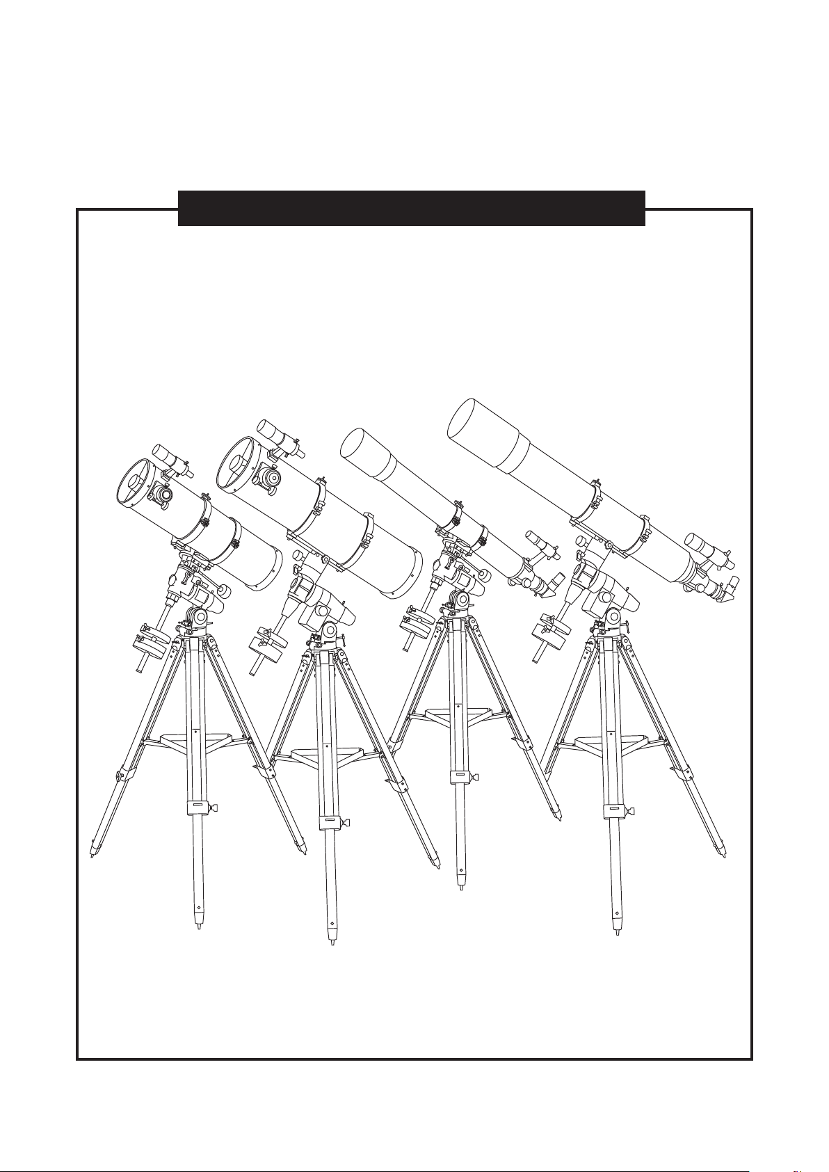
Telescopes with NEQ3 & EQ5 Mount
031007V3
Page 2
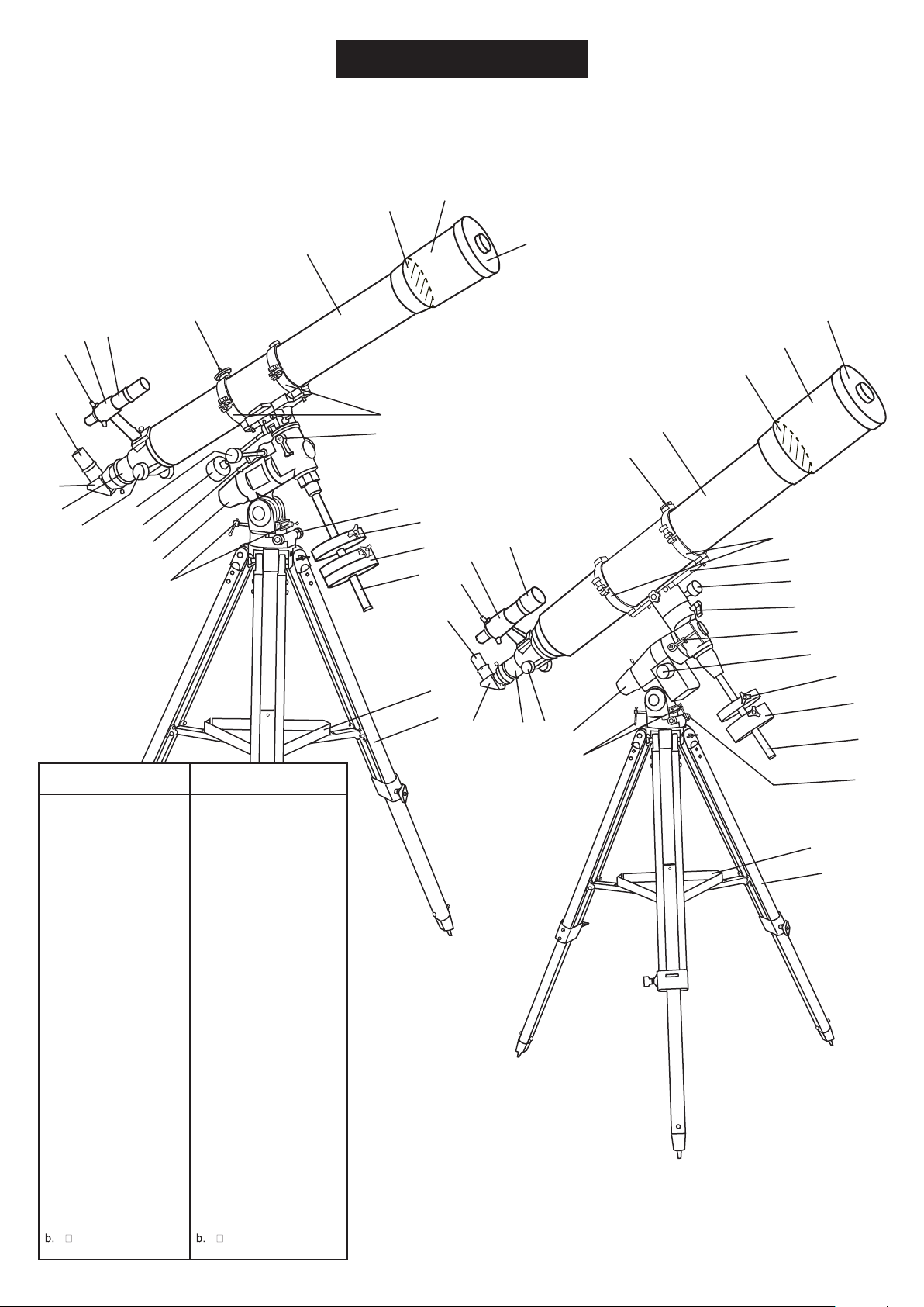
REFRACTOR
B
A
EQ5
A
B
H
G
NEQ3
C
D
E
F
C
I
11
10
D
E
J
K
1
L
2
3
4
5
9
8
7
G
6
H
I
F
12
(150mm/1200mm)
11
10
9
8
7
a
b
J
K
L
1
6
5
4
2
EQ3-2
EQ5
3
Dust Cap/Mask
A.
(Remove before Viewing)
Sun Shade
B.
Objective Lens
C.
Telescope Main Body
D.
Piggyback Bracket
E.
Finderscope
F.
Finderscope Bracket
G.
Alignment Screw
H.
Eyepiece
I.
Diagonal
J.
Focus Tube
K.
Focus Knob
L.
1.
R.A. Flexible Control
Cable
2.
Dec. Flexible Control
Cable
3.
R.A. Lock knob
4.
Polarscope Holder
(not shown)
5.
Altitude Adjustment T-bolts
6.
Counterweight Rod
7.
Counterweight
8.
Counterweight Thumb
Screw
9.
Azimuth Adjustment Knob
10.
Dec. Lock Knob
11.
Tube Rings
a.
Accessory Tray
Tripod Leg
Dust Cap/Mask
A.
(Remove before Viewing)
Sun Shade
B.
Objective Lens
C.
Telescope Main Body
D.
Piggyback Bracket
E.
Finderscope
F.
Finderscope Bracket
G.
Alignment Screw
H.
Eyepiece
I.
Diagonal
J.
Focus Tube
K.
Focus Knob
L.
Polarscope Holder
1.
(not shown)
Altitude Adjustment T-bolts
2.
Azimuth Adjustment Knob
3.
Counterweight Rod
4.
Counterweight
5.
Counerweight Thumb
6.
Screw
R.A. Control Knob
7.
R.A. Lock Knob
8.
Dec. Lock Knob
9.
Dec. Control Knob
10.
Mounting Plate
11.
(150mm/1200mm)
Tube RIngs
12.
a.
Accessory Tray
Tripod Leg
a
b
2
Page 3
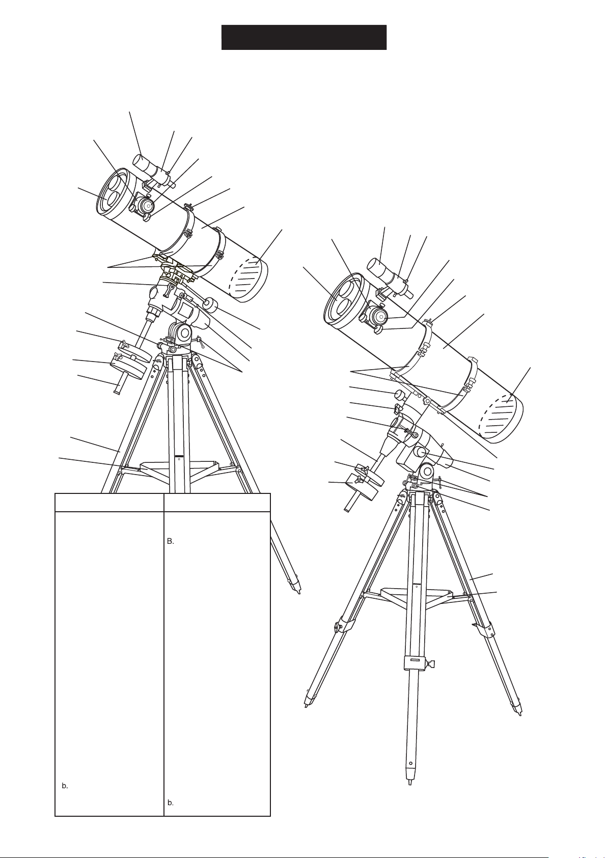
REFLECTOR
C
B
NEQ3
D
E
F
G
A
H
EQ5
I
J
B
10
A
9
8
7
1
C
D
E
F
G
H
I
2
6
5
3
4
12
11
10
9
J
a
b
Dust Cap/Mask
A.
(Remove before Viewing)
Focus Tube
B.
Finderscope
C.
Finderscope Bracket
D.
Finderscope Adjustment
E.
Screws
Eyepiece
F.
Focus Knob
G.
Piggyback Bracket
H.
Telescope Main Body
I.
Primary Mirror Position
J.
1.
Dec. Flexible Control
Cable
2.
R.A. Lock Knob
3.
Polarscope Holder
(not shown)
4.
Altitude Adjustment T-bolts
5.
Counterweight Rod
6.
Counterweight
7.
Counterweight Thumb
Screw
8.
Azimuth Adjustment Knob
9.
Dec. Lock Knob
10.
Tube Rings
a.
Tripod Leg
Accessory Tray
EQ5EQ3-2
Dust Cap/Mask
A.
(Remove before Viewing)
Focus Tube
Finderscope
C.
Finderscope Bracket
D.
Finderscope Adjustment
E.
Screws
Eyepiece
F.
Focus Knob
G.
Piggyback Bracket
H.
Telescope Main Body
I.
Primary Mirror Position
J.
Mounting Plate
1.
(200mm/1000mm)
R.A. Control Knob
2.
Polorscope Holder
3.
(not shown)
Altitude Adjustment T-bolts
4.
Azimuth Adjustment Knob
5.
Counterweight
6.
Counterweight Thumb
7.
Screw
Counterweight Rod
8.
R.A. Lock Knob
9.
Dec. Lock Knob
10.
Dec. Control Knob
11.
Tube Rings
12.
a.
Tripod Leg
Accessory Tray
8
(200mm/1000mm)
7
1
2
6
3
4
5
a
b
3
Page 4
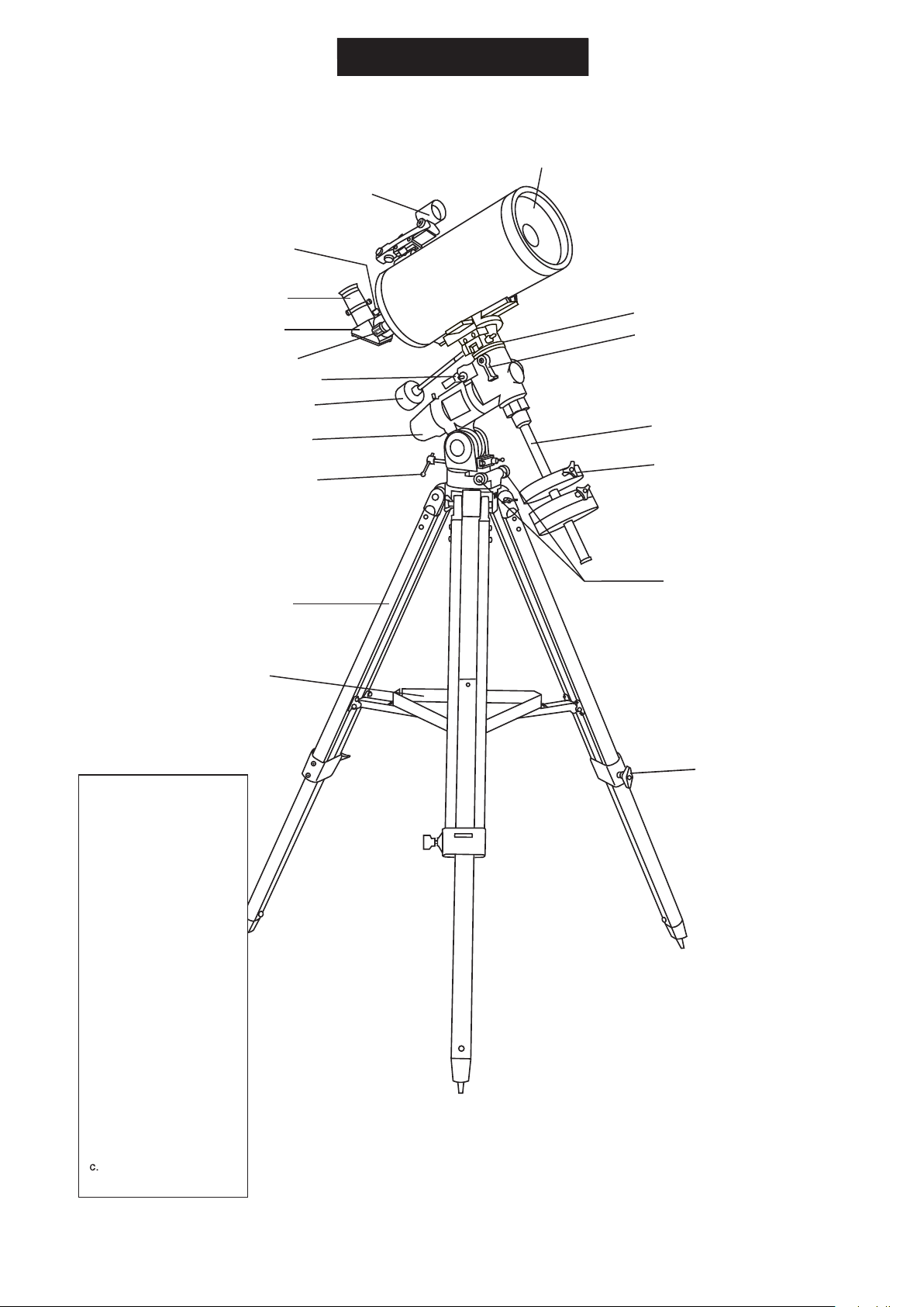
MAKSUTOV
NEQ3
A
B
C
D
E
9
8
F
1
2
7
3
6
4
5
a
Dust Cap (not shown,
A.
remove before Viewing)
Red Dot Finder
B.
Focus Locking Screw
C.
D.
Eyepiece
E.
Diagonal
F.
Focusing Knob
1.
R.A Lock Knob
2.
Dec Flexible Control
Cable
3.
Polarscope Holder/
Polarscope (not shown,
optional)
4.
Altitude Adjustment T-bolt
5.
Azimuth Adjustment
Knobs
6.
Counterweight Locking
Thumb Screw
7.
Counterweight Rod
8.
Dec Lock Knob
9.
Dec Setting Circle
b
c
a.
Tripod Leg
b.
Accessory Tray
Height Adjustment
Clamp
4
Page 5
TABLE OF CONTENTS
Assembling Your Telescope
For NEQ3
Tripod Set up
Telescope Assembly
Finderscope/Red Dot Finder Assembly
Eyepiece Assembly
For EQ5
Tripod Set up
Telescope Assembly
Finderscope Assembly
Eyepiece Assembly
Operating Your Telescope
Aligning the Finderscope
Using the Red Dot Finder
Balancing the telescope
Using the leveling bubble
Operating the NEQ3 Mount
Operating the EQ5 Mount
Using the Barlow Lens
Focusing
Polar Alignment for visual use
Pointing your telescope
Using the setting circles
Choosing the appropriate eyepiece
6
6
6
7
7
8
8
9
9
10
10
10
11
11
12
12
13
13
13
14
16
18
Observing the Sky
Sky Conditions
Selecting an Observing Site
Choosing the Best Time to Observe
Chooling the Telescope
Adapting Your Eyes
Proper Care for Your Telescope
Collimating a Newtonian reector
Collimating a refractor (with the adjustable objective-lens cell)
Cleaning Your Telescope
Appendix A-Precise polar alignment for Northern Hemisphere
Appendix B-Optional Accessories
Appendix C-Recommended Reading
efore you begin
B
This instruction manual is applicable to all the models with the EQ3-2 or EQ5 mount. Take a moment
to find the model closest to your telescope on p.2 p.3, and p4. Follow the instructions for your specific
model in the manual. Read the entire instructions carefully before beginning. Your telescope should
be assembled during daylight hours. Choose a large, open area to work to allow room for all parts to
be unpacked.
19
19
19
19
19
19
20
20
22
22
I
III
IV
Page 6
FOR NEQ3 MOUNT
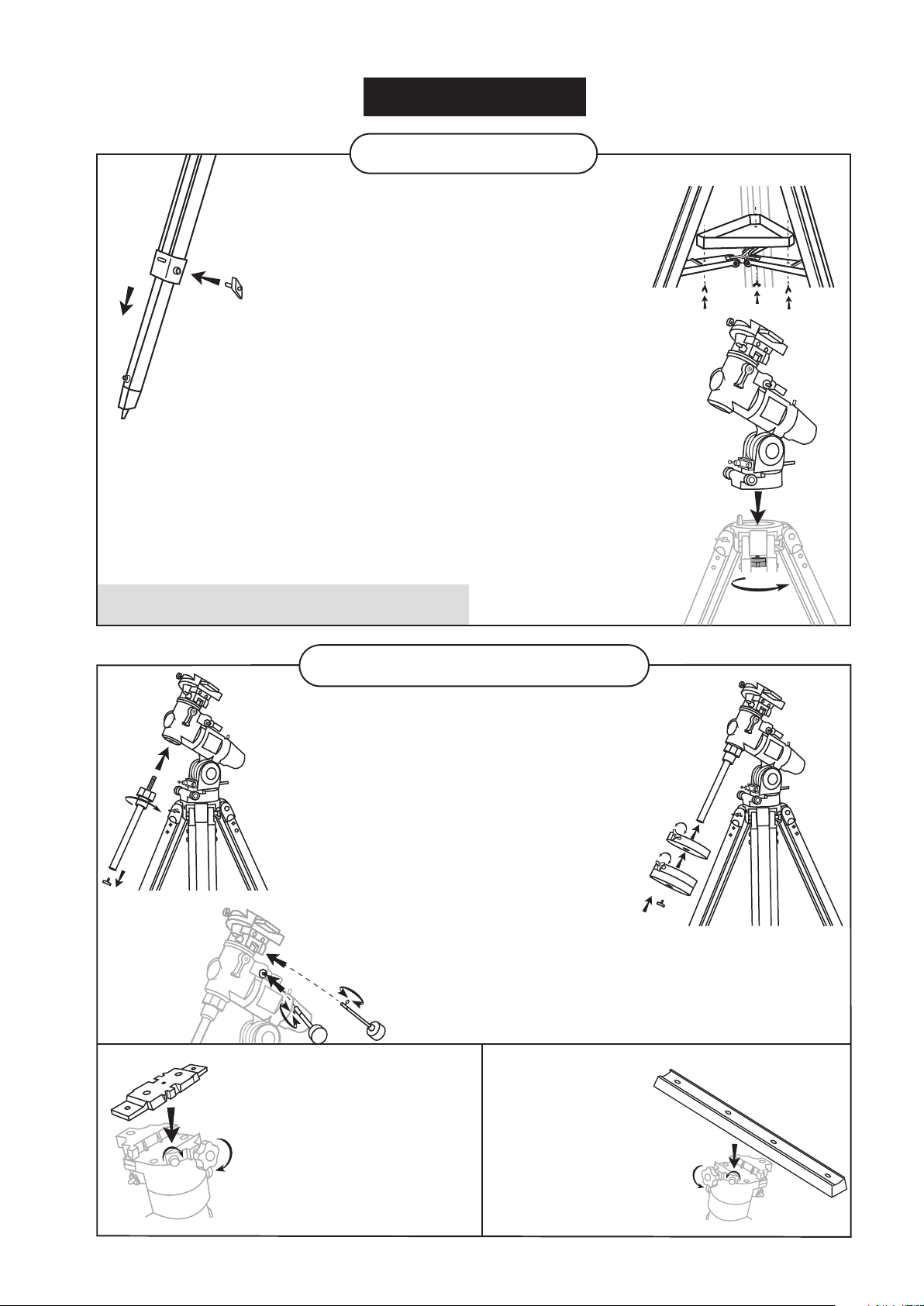
TRIPOD SET UP
Fig. 1
ADJUSTING THE TRIPOD LEGS (Fig.18)
1) Slowly loosen the height adjustment clamp and
gently pull out the lower section of each tripod leg.
Tighten the clamps to hold the legs in place.
2) Spread the legs apart to stand the tripod upright.
3) Adjust the height of each tripod leg until the
tripod head is properly leveled. Note that the
tripod legs may not be at same length when
the equatorial mount is level. Do not over tighten
the clamps.
ATTACHING THE ACCESSORY TRAY (Fig.2)
1) Place the accessory tray on top of the bracket, and
secure with the locking thumb screws from underneath.
ATTACHING THE MOUNT TO THE TRIPOD (Fig.3)
1) Align metal dowel on the tripod head with the gap
between the azimuthal adjustment knobs underneath
the mount. Tighten the knurled knob underneath the
tripod head to secure mount to tripod.
Note: Loosen the azimuthal adjustment knobs if mount does not
fit into tripod head completely. Retighten knobs to secure.
Fig. 2
Fig. 3
Fig. 7
TELESCOPE ASSEMBLY
Fig. 4
ATTACHINGTHE MOUNTING
PLATE (Fig.7)
1) Align the screws with the grooves
2) Secure by tightening the two
INSTALLING THE COUNTERWEIGHT(S) (Fig.4, 5)
1) Locate the counterweight rod.
2) Screw the counterweight rod into the threaded hole
on the end of the declination shaft. Tighten the locknut
on counterweight rod until it is locked against the mount.
3) Unscrew the threaded cap from the end of the
counterweight rod.
4) Locate the counterweight(s) and slide them
halfway along the counterweight rod.Tighten
the counterweight thumbscrews to secure.
5) Replace the cap on the end of the
counterweight rod.
INSTALLING THE CONTROL CABLES (Fig.6)
1) Slide the sleeve end of the cable over the
(short mounting plate)
on the side of the mounting bar.
Position the mounting plate
on the mounting bracket.
locking screws.
Fig. 5
nipple on the end of the worm gear. Secure
the cable by tightening the set screw against
the flat surface of the nipple.
(long mounting plate)
Fig. 8
ATTACHING THE
MOUNTING PLATE (Fig.8)
1) Position the mounting plate
on the mounting bracket.
2) Secure by tightening
the two locking screws.
6
Page 7
TELESCOPE ASSEMBLY
ATTACHING THE TUBE RINGS TO THE MOUNT (Fig.9)
1) Remove the telescope tube assembly from
its plastic packaging.
2) Remove the tube rings from the telescope by
releasing their thumb nuts and opening their hinges.
3) Using the bolts provided, fasten the tube rings to
the mount with the 10mm wrench provided.
ATTACHING THE TELESCOPE MAIN TUBE
TO THE TUBE RINGS (Fig.10)
1) Remove the telescope tube from the paper covering.
2) Find the center of balance of the telescope tube.
Place this in between the two tube rings. Close the
hinges around the telescope and fasten securely by
tightening the thumb nuts. Do not over tighten.
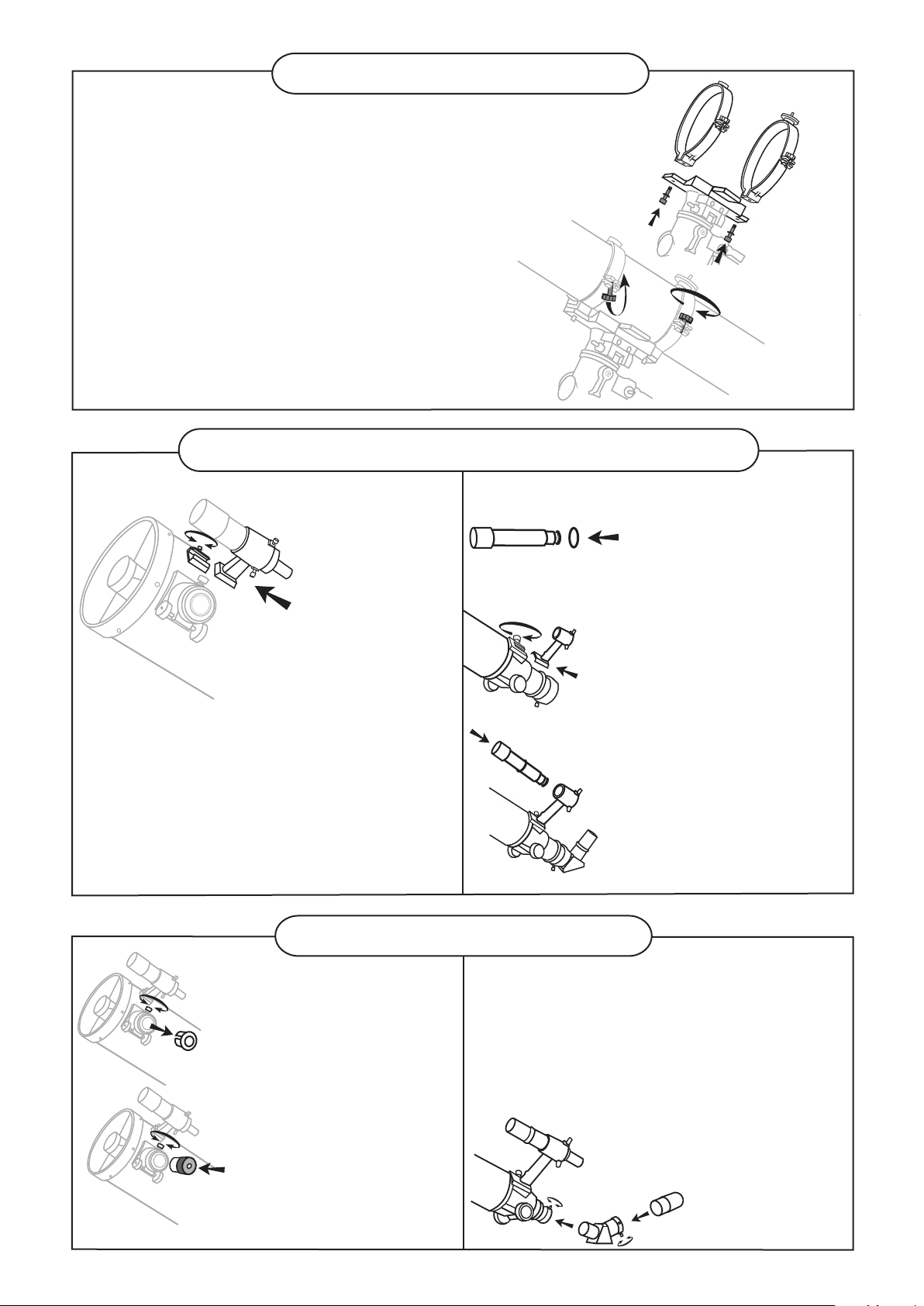
FINDERSCOPE/RED DOT FINDER ASSEMBLY
(reector and Maksutov)
Fig.11
ATTACHING THE FINDERSCOPE
BRACKET/RED DOT FINDER (Fig.11)
1) Locate the nderscope optical assembly
or Red Dot Finder.
2) Slide the nderscope bracket/Red Dot
Finder into the rectangular slot and tighten
the screw to hold the mount in place.
Fig.10
(refractor)
Fig.12
Fig.13
Fig.14
Fig.9
ATTACHING THE FINDERSCOPE (Fig.12, 13, 14)
1) Locate the nderscope bracket.
Carefully remove the rubber-o ring from the nderscope bracket.
2) Position the o-ring into the
groove located approximately
half-way along the nderscope
tube.
3) Locate the nderscope optical
assembly.
4) Slide the nderscope bracket
into the rectangular slot and
tighten the screw to hold the
mount in place.
5) Position the nderscope into
its mount by sliding it backwards
until the rubber o-ring seats
in the nderscope mount.
Fig.15
Fig.16
EYEPIECE ASSEMBLY
(reector)
INSERTING THE EYEPIECE
(Fig.15, 16)
1) Unscrew the thumbscrews
on the end of the focus tube
to remove the black plastic
end-cap.
2) Insert the desired eyepiece
and secure it by retightening
the thumbscrews.
(refractor and
Maksutov)
Fig.17
7
INSERTING THE EYEPIECE
(Fig.17)
1) Loosen the thumbscrew on the
end of the focus tube.
2) Insert the diagonal into the focus
tube and re-tighten the thumbscrew
to hold the diagonal in place.
3) Loosen the thumbscrews
on the diagonal.
4) Insert the desired eyepiece
into diagonal and secure by re tightening the thumbscrews.
Page 8

FOR EQ5 MOUNT
TRIPOD SET UP
Fig.18
1) Slowly loosen the height adjustment clamp and
gently pull out the lower section of each tripod leg.
Tighten the clamps to hold the legs in place.
2) Spread the legs apart to stand the tripod upright.
3) Adjust the height of each tripod leg until the
tripod head is properly leveled. Note that the
tripod legs may not be at same length when
the equatorial mount is level. Do not over tighten
the clamps.
ATTACHING THE ACCESSORY TRAY (Fig.19)
ADJUSTING THE TRIPOD LEGS (Fig.18)
1) Place th e accessory tray on top of the bracket, and
secure with the locking thumb screws from underneath.
ATTACHING MOUNT TO TRIPOD (Fig.20)
1) Align metal dowel on the tripod head with the gap
between the azimuthal adjustment knobs underneath
the mount. Tighten the knurled knob underneath the
tripod head to secure mount to tripod.
Note: Loosen the azimuthal adjustment knobs if mount does not
t into tripod head completely. Retighten knobs to secure.
Fig.19
Fig.20
Fig.23
TELESCOPE ASSEMBLY
INSTALLING COUNTERWEIGHT (Fig.21, 22)
Fig.21
ATTACHING THE MOUNTING
PLATE (Fig.23)
1) Position the mounting plate
on the mounting bracket.
2) Secure by tightening the two
locking screws.
Note: The screws should align with the
grooves in the side of the mounting bar.
1) Locate counterweight rod.
2) Screw counterweight rod into threaded hole on the
end of the declination shaft. Tighten locknut on the
counterweight rod until it is locked against the mount.
3) Unscrew the threaded cap from the end of the
counterweight rod.
4) Locate the counterweights and slide them halfway
along the counterweight rod. Tighten the counterweight
thumb screws to secure.
5) Replace the cap on the end of the counterweight rod.
(short mounting plate)
Fig.22
(long mounting plate)
Fig.24
ATTACHING THE
MOUNTING PLATE (Fig.24)
1) Position the mounting plate
on the mounting bracket.
2) Secure by tightening
the two locking screws.
8
Page 9
TELESCOPE ASSEMBLY
ATTACHING THE TUBE RINGS TO THE MOUNT(Fig.25)
1) Remove the telescope tube assembly
from its plastic packaging.
2) Remove the tube rings from the telescope by releasing
their thumb nuts and opening their hinges.
3) Using the bolts provided, fasten the tube rings to
the mount with the 10mm wrench provided.
ATTACHING THE TELESCOPE
MAIN TUBE TO THE TUBE RINGS (Fig.26)
1) Remove the telescope tube from the paper covering.
2) Find the center of balance of the telescope tube.
Place this in between the two tube rings. Close the
hinges around the telescope and fasten securely by
tightening the thumb nuts.
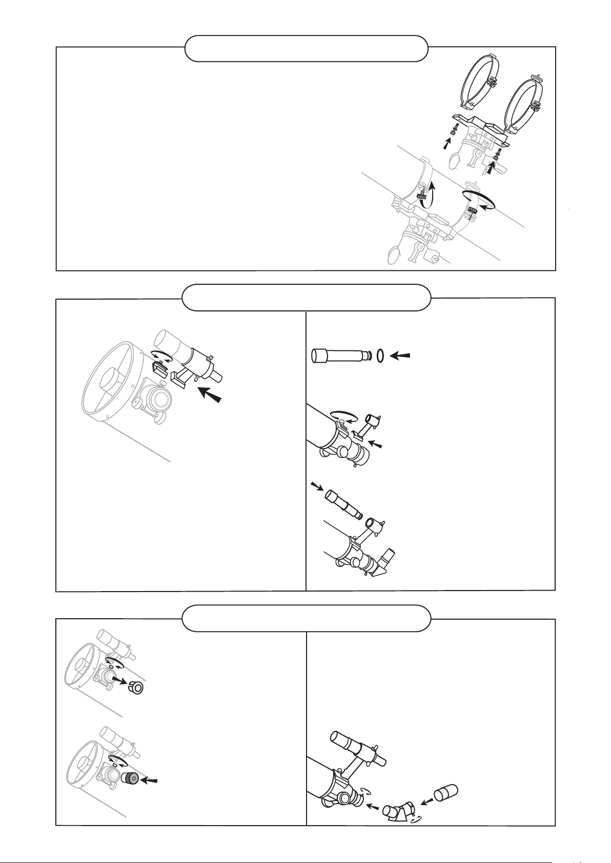
FINDERSCOPE ASSEMBLY
(reector)
Fig.27
ATTACHING THE FINDERSCOPE
BRACKET (Fig.27)
1) Locate the nderscope optical assembly.
2) Slide the nderscope bracket into
the rectangular slot and tighten the
screw to hold the mount in place.
Fig.26
(refractor)
Fig.28
Fig.29
Fig.30
Fig.25
ATTACHING THE FINDERSCOPE (Fig.28, 29, 30)
1) Locate the nderscope
bracket. Carefully remove
the rubber-o-ring from the
nderscope bracket.
2) Position the o-ring into the
groove located approximately
half-way along the nderscope
tube.
3) Locate the nderscope optical
assembly.
4) Slide the nderscope bracket
into the rectangular slot and
tighten the screw to hold the
mount in place.
5) Position the nderscope into its
mount by sliding it backwards
until the rubber o-ring seats
in the nderscope mount.
Fig.31
Fig.32
EYEPIECE ASSEMBLY
(reector)
INSERTING THE EYEPIECE
(Fig.31, 32)
1) Unscrew the thumbscrews
on the end of the focus
tube to remove the black
plastic end-cap.
2) Re-tighten thumb screws to
hold the eyepiece in place.
(refractor)
Fig.33
9
INSERTING THE EYEPIECE
(Fig.33)
1) Loosen the thumbscrew on the
end of the focus tube.
2) Insert the diagonal into the focus
tube and re-tighten thumbscrew
to hold the diagonal in place.
3) Loosen the thumbscrews
on the diagonal.
4) Insert the desired eyepiece
into diagonal and secure by
re-tightening the thumbscrews.
Page 10
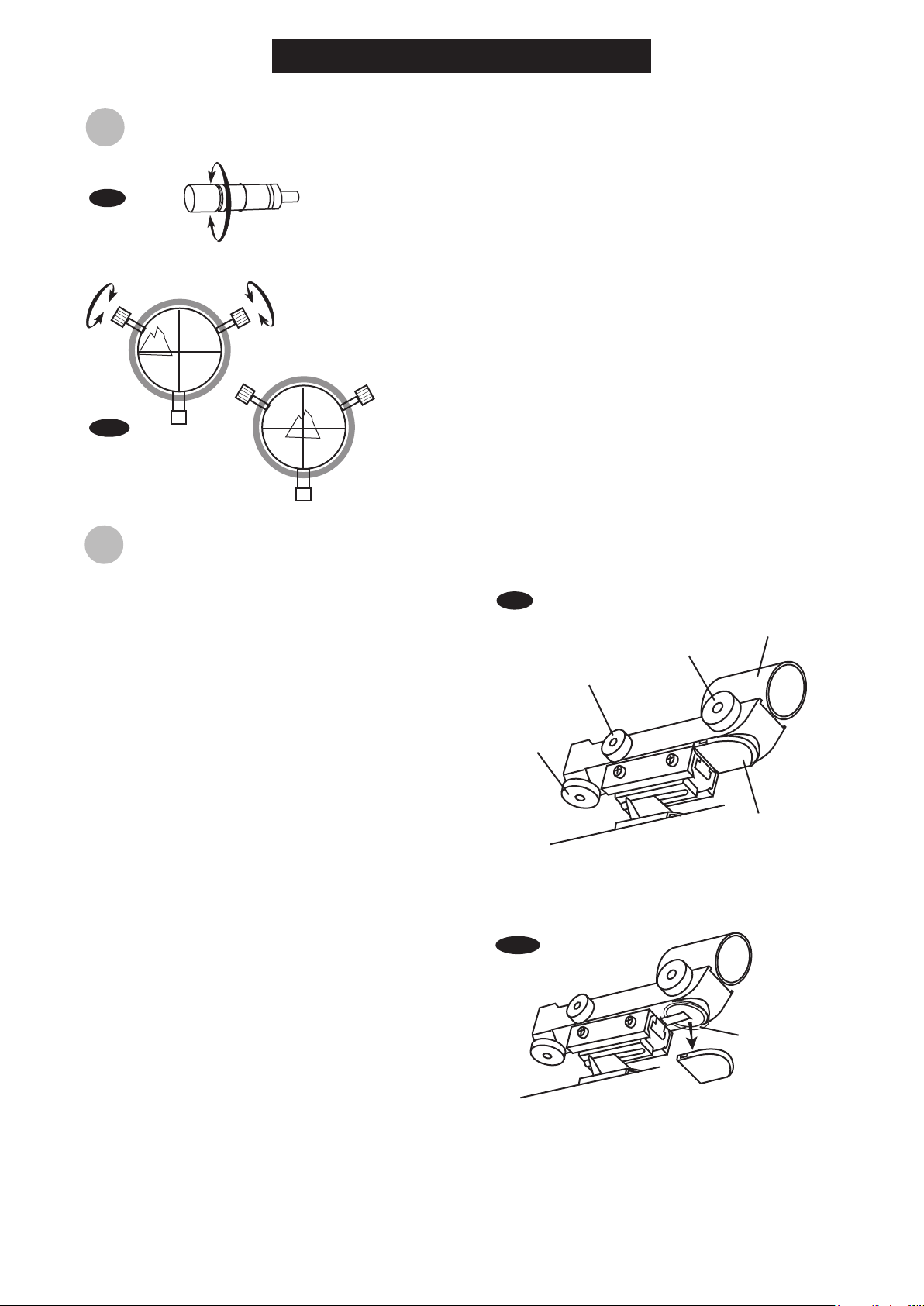
ligning the nde
A
Fig.a
Fig.a1
OPERATING YOUR TELESCOPE
scope
r
The finderscope (optical or red dot) is a very useful accessory
that is included with your telescope. When the finderscope is
correctly aligned with the telescope, objects can be quickly
located and brought to the centre of the field. Alignment is best
done outdoors in day light when it's easier to locate objects. If
it is necessary to refocus your finderscope, sight on an object
that is at least 500 yards (metres) away. Loosen the locking
ring by unscrewing it back towards the bracket. The front lens
holder can now be turned in and out to focus. When focus is
reached, lock it in position with the locking ring (Fig.a).
1)
Choose a distant object that is at least 500 yards away and
point the main telescope at the object. Adjust the telescope
so that the object is in the centre of the view in your
eyepiece.
2)
Check the finderscope to see if the object centred in the
main telescope view is centred on the crosshairs.
3)
Adjust the two small screws to centre the finderscope
crosshairs on the object (Fig.a1).
scope
sing the Red Dot Finde
U
The Red Dot Finder is a zero magnification pointing
tool that uses a coated glass window to superimpose
the image of a small red dot onto the night sky. The
Red Dot Finder is equipped with a variable brightness
control, azimuth adjustment control, and altitude
adjustment control (Fig.b). The Red Dot Finder is
powered by a 3-volt lithium battery located underneath
at the front. To use the Finder, simply look through the
sight tube and move your telescope until the red dot
merges with the object. Make sure to keep both eyes
open when sighting.
Aligning the Red Dot Finder
Like all finderscopes, the Red Dot Finder must be
properly aligned with the main telescope before use.
This is a simple process using the azimuth and altitude
control knobs.
1)
Open the battery cover by pulling it down (you can
gently pry at the 2 small slots) and remove the
plastic shipping cover over the battery (Fig.b1).
2)
Turn on the Red Dot Finder by rotating the variable
brightness control clockwise until you hear a "click".
Continue rotating the control knob to increase the
brightness level.
3)
Insert a low power eyepiece into the telescope's
focuser. Locate a bright object and position the
telescope so that the object is in the centre of the
field of view.
4)
With both eyes open, look through the sight tube at
the object. If the red dot overlaps the object, your
Red Dot Finder is perfectly aligned. If not, turn its
azimuth and altitude adjustment controls until the
red dot is merged with the object.
r
Fig.b
Altitude
Adjustment
Control
Fig.b1
ON/OFF
Brightness
Control
Azimuth
adjustment
control
Sight Tube
Battery cover
Plastic
shipping
cover
10
Page 11
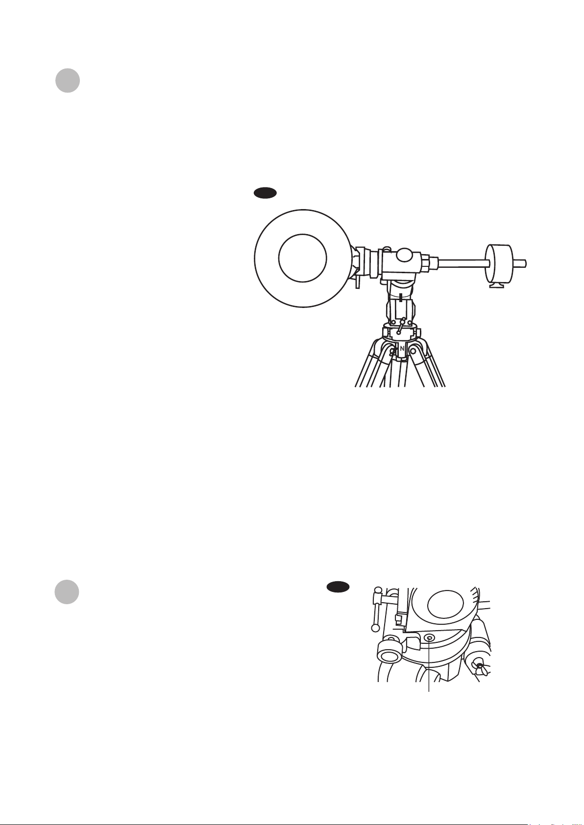
alancing the telescope
B
A Telescope should be balanced before each observing session. Balancing reduces stress on the telescope
mount and allows precise control of micro-adjustment. A balanced telescope is specially critical when using
the optional clock drive for astrophotography. The telescope should be balanced after all accessories
(eyepiece, camera, etc.) have been attached. Before balancing your telescope, make sure that your tripod is
balanced and on a stable surface. For photography, point the telescope in the direction you will be taking
photos before performing the balancing steps.
R.A. Balancing
1)
For best results, adjust the altitude of
the mount to between 15º and 30º if
possible, by using the altitude
adjustment T-bolt.
2)
Slowly unlock the R.A. and Dec. lock
knobs. Rotate the telescope until
both the optical tube and the
counterweight rod are horizontal to
the ground, and the telescope tube
is to the side of the mount (Fig.c).
3)
Tighten the Dec. lock knob.
4)
Move the counterweight(s) along the
counterweight rod until the
telescope is balanced and remains
stationary when released.
5)
Tighten the counterweight thumb
screws to hold counterweight(s) in
their new position.
Dec. Balancing
All accessories should be attached to the telescope before balancing around the declination axis. The R.A.
balancing should be done before proceeding with Dec. balancing.
1)
For best results, adjust the altitude of the mount to between 60º and 75º if possible.
2)
Release the R.A. lock knob and rotate around the R.A. axis so that the counterweight rod is in a horizontal
position. Tighten the R.A. lock knob.
3)
Unlock the Dec. lock knob and rotate the telescope tube until it is parallel to the ground.
4)
Slowly release the telescope and determine in which direction it rotates. Loosen the telescope tube rings and
slide the telescope tube forward or backward in the rings until it is balanced.
5)
Once the telescope no longer rotates from its parallel starting position, re-tighten the tube rings and the Dec.
lock knob. Reset the altitude axis to your local latitude.
Fig.c
N
sing the le
U
For best telescope performance, the equatorial mount
should be properly leveled. A level tripod allows easier
fine adjustment of controls and better weight distribution.
This equatorial mount includes a small leveling bubble
near its base (Fig.d). Adjust the height of each tripod leg
until the bubble appears in the center of the circle. Note
that the tripod legs may not be at same length when the
equatorial mount is level.
veling
b
11
le
b
ub
Fig.d
Leveling bubble
Page 12
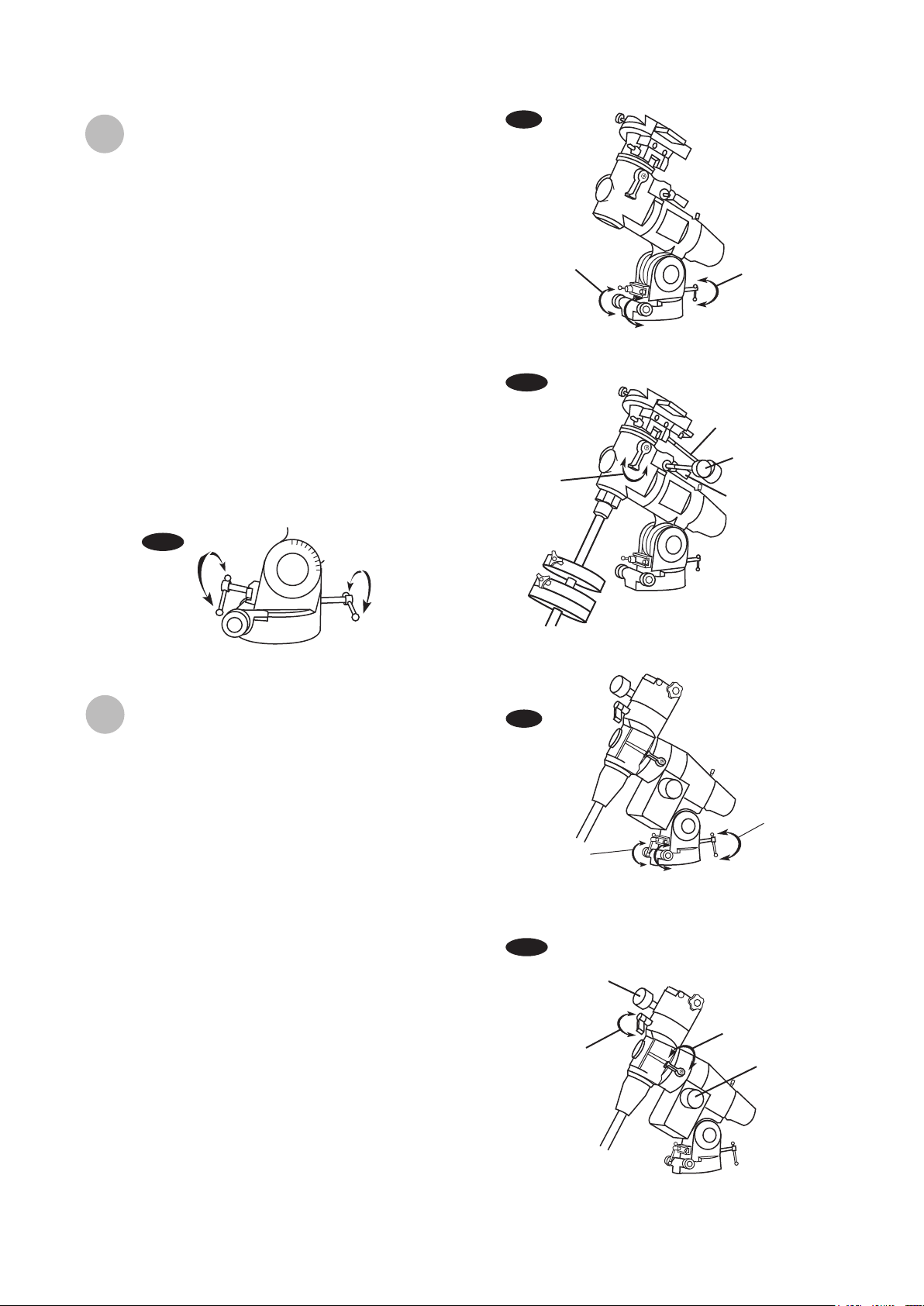
perating the NEQ3 mount
O
The NEQ3 mount has controls for both conventional
altitude (up-down) and azimuth (left-right) directions of
motion. These two adjustments are suggested for large
direction changes and for terrestrial viewing. The two
azimuth adjustment knobs located near the tripod head
allow fine-adjustment of azimuth for polar alignment.
Use the altitude adjustment T-bolts for altitude
adjustments. These allow fine-adjustment for setting the
mount to your local latitude. (Fig.e).
In addition, this mount has Right Ascension (hour
angle) and Declination direction controls for
polar-aligned astronomical observing. Loosen the lock
knobs to make large direction changes. Use the control
cables for fine adjustment after the lock knobs have
both been locked (Fig.e1). An additional scale is
included for the altitude axis. This allows polar
alignment for your local latitude. (Fig.e2)
Fig.e
Azimuth
adjustment
Fig.e1
Dec.
adjustment
Altitude
adjustment
Dec. fine
adjustment
R.A. fine
adjustment
R.A. adjustment
Fig.e2
0
10
20
30
40
50
60
70
80
90
Latitude scale
perating the EQ5 mount
O
The EQ5 mount has controls for both conventional
altitude (up-down) and azimuth (left-right) directions of
motion. These two adjustments are suggested for
large direction changes and for terrestrial viewing. The
two azimuth adjustment knobs located near the tripod
head allow fine-adjustment of azimuth for polar
alignment. Use the altitude adjustment T-bolts for
altitude adjustments. These allow fine-adjustment for
setting the mount to your local latitude. (Fig.f).
In addition, this mount has Right Ascension (hour
angle) and declination direction controls for
polar-aligned astronomical observing. Loosen the lock
knobs to make large direction changes. Use the
control cables for fine adjustment after the lock knobs
have both been locked (Fig.f1). An additional scale is
included for the altitude axis. This allows polar
alignment for your local latitude. (Fig.e2)
Fig.f
Azimuth
adjustment
Fig.f1
Dec. fine
adjustment
Dec. adjustment
Altitude
adjustment
R.A. adjustment
R.A. fine
adjustment
12
Page 13
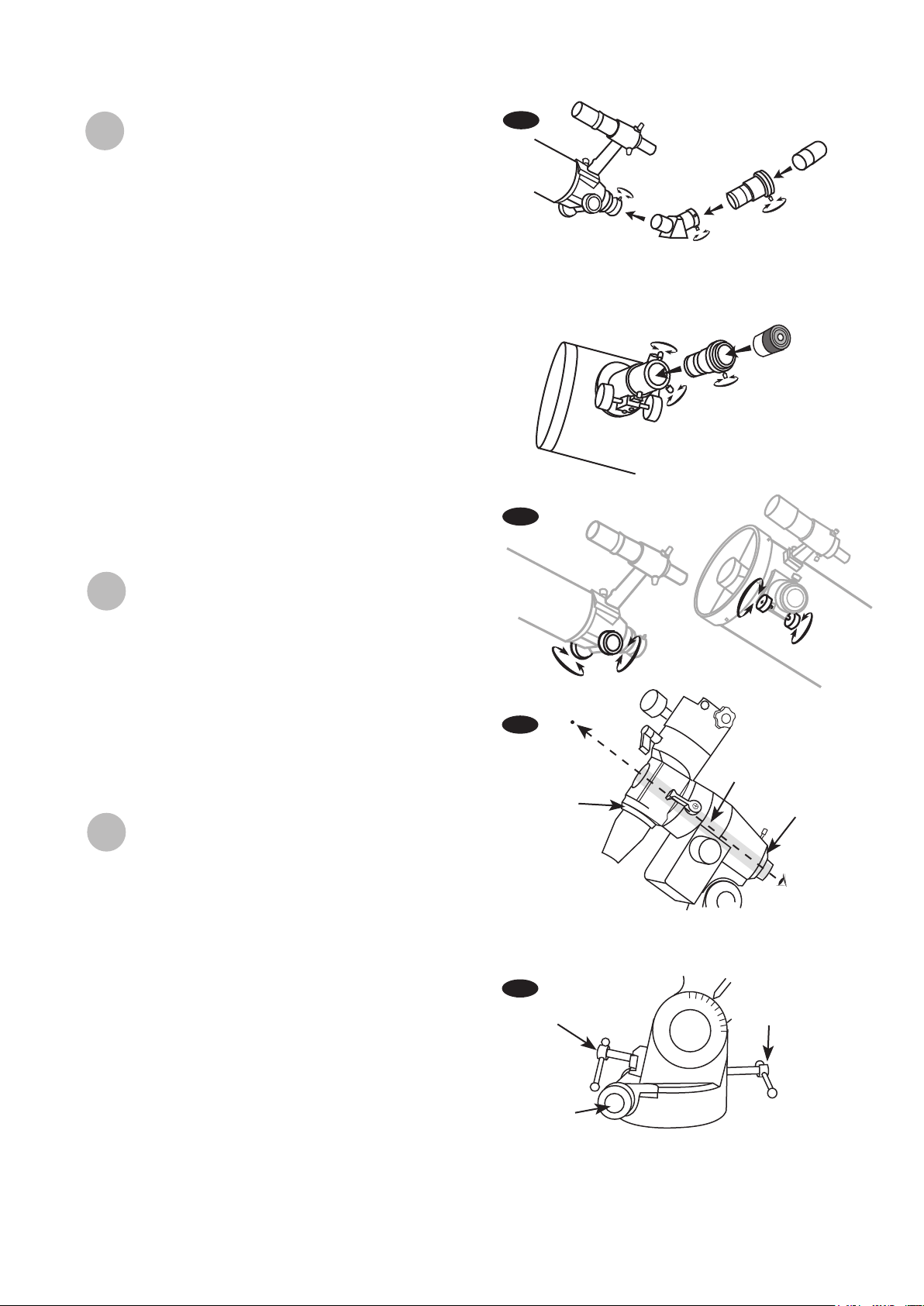
w lens (optional)
sing the Barl
U
o
A Barlow is a negative lens which increases the
magnifying power of an eyepiece, while reducing the
field of view. It expands the cone of the focussed light
before it reaches the focal point, so that the telescope's
focal length appears longer to the eyepiece.
The Barlow is inserted between the focuser and the
eyepiece in a reflector, and usually between the diagonal
and the eyepiece in a refractor or a maksutov (Fig.g).
With some telescopes, it can also be inserted between
the focuser and the diagonal, and in this position it gives
even greater magnification. For example, a 2X Barlow
when inserted after the diagonal can become 3X when
placed in front of the diagonal.
Fig.g
Barlow
Diagonal
(Refracting Telescopes
and Maksutovs)
Barlow
Eyepiece
Eyepiece
In addition to increasing magnification, the benefits of
using a Barlow lens include improved eye relief, and
reduced spherical aberration in the eyepiece. For this
reason, a Barlow plus a lens often outperforms a single
lens producing the same magnification. However, its
greatest value may be that a Barlow effectively doubles
the number of eyepieces in your collection.
ocusing
F
Slowly turn the focus knobs under the focuser, one way
or the other, until the image in the eyepiece is sharp
(Fig.h). The image usually has to be finely refocused
over time, due to small variations caused by temperature
changes, flexures, etc. This often happens with short
focal ratio telescopes, particularly when they haven't yet
reached outside temperature. Refocusing is almost
always necessary when you change an eyepiece or add
or remove a Barlow lens.
Visual Use
or
olar Alignment
P
f
Tracking of celestial objects can be simplified by
performing a procedure known as a polar alignment. For
visual use the procedure does not require high precision.
For satisfactory results all you need to do is point your
mount at Polaris, the North Star.
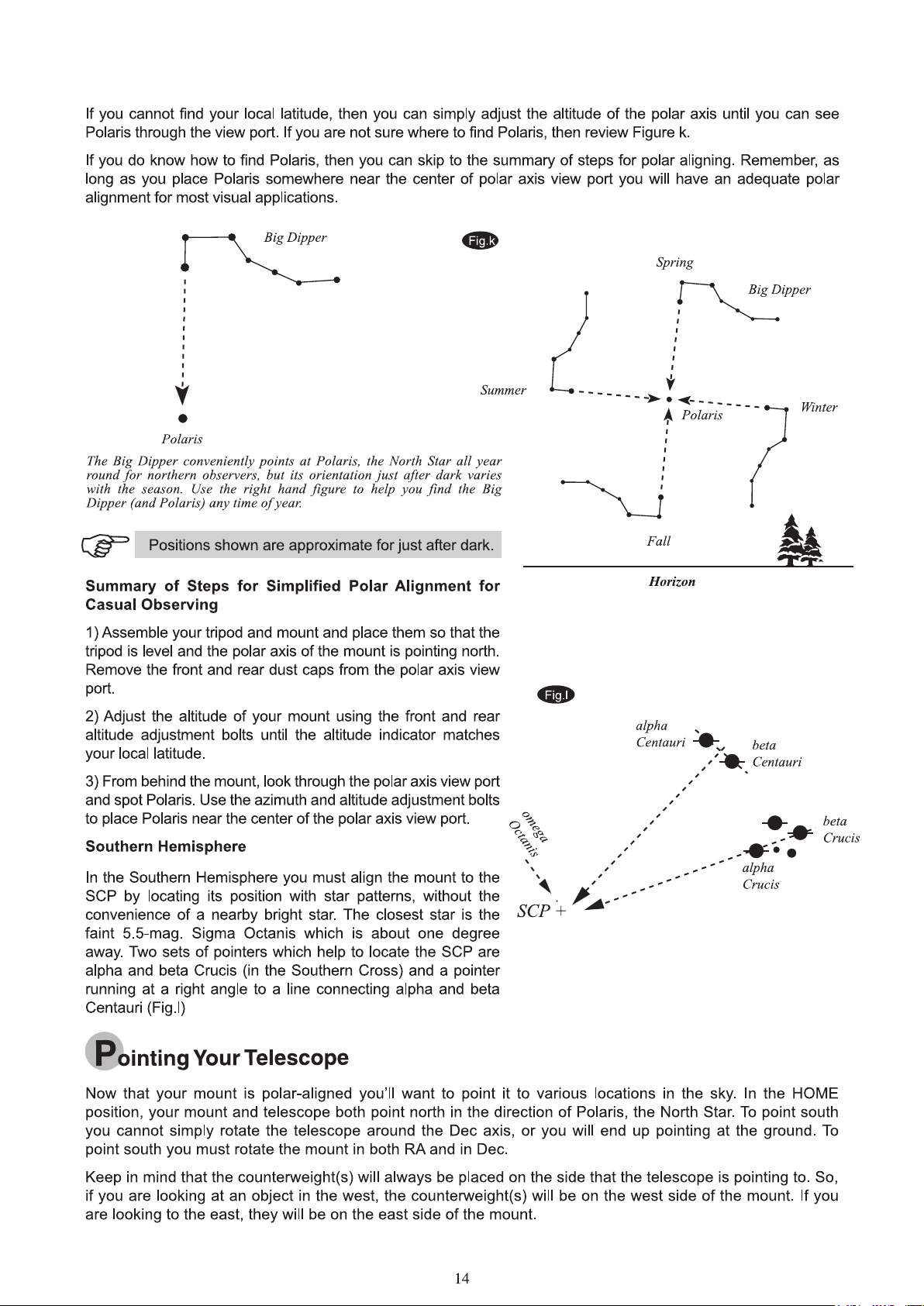
To point at Polaris, start by aiming the north leg of the
tripod north. Next, adjust the altitude angle of the mount so
that you can see Polaris through the polar axis view port.
Note that the proper altitude angle is equal to your local
latitude. If you know your local latitude simply adjust the
front and back latitude adjustment bolts until the indicator
points to your local latitude on the scale. Fig. j. To find your
local latitude you can consult a road map, call your airport,
or look it up on the Internet.
(Reflecting Telescopes)
Fig.h
Polaris
Fig.i
Polaris axis
view point
Dec. setting
circle
If you can see Polaris through your polar scope
view port, you are polar aligned sufficiently for
most visual applications.
Fig.j
Front Latitude
adjuster
Azimuth
adjusters
These are the main controls for adjusting the position of
your mount to aim it at Polaris. Here, the latitude is set to
approximately 40 degrees. East/west adjustments are made
with the Azimuth adjusters.Up/down adjustments are made
with the Latitude adjusters.
0
10
20
30
40
50
60
70
80
90
R.A Setting circle
Rear Latitude
adjuster
13
Page 14
Page 15
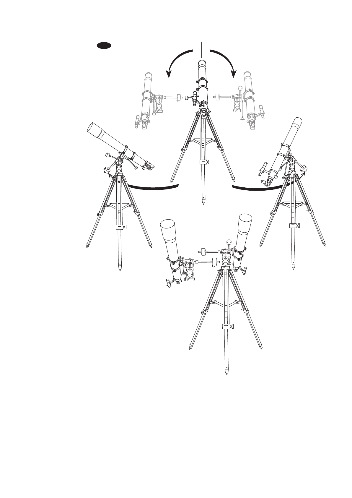
Fig.m
You aim your telescope by rotating it along the RA and
Dec axes of your mount. In the upper image the
telescope is in the HOME position, aimed due north.
The side images show the telescope pointing NE (right
side) and SW (left side). The bottom image shows the
telescope pointing due south.
After pointing at an object and tracking it for a while you may find the counterweight(s) rise above the point of
being parallel to the ground. If so, it is time to perform a meridian flip. This is necessary to prevent your
telescope from eventually colliding with the mount or tripod.
To do a meridian flip, rotate your telescope 180 degrees in Dec and lock the Dec axis. Now, rotate your mount
12H in RA and lock the RA axis. Using the setting circles to assist you will help you do this more accurately.
When finished you should be pointing at the same object you were pointing at before, but from the opposite side
of your mount. Don’t forget to adjust your RA setting circles back to the coordinates of your object. Lock the
setscrew when done.
15
Page 16
sing the Setting Cir
U
c
les
Now it is time to learn what those numbered dials are for!
The dials are called setting circles and they can be used
Fig.n
0
2
4
6
8
10
to help you find objects in the sky simply by dialing in a
set of coordinates.
All objects in the sky have assigned coordinates labeled
Right Ascension (RA for short) and Declination (Dec for
short). The RA axis follows east/west movement of the
1
2
3
21
4
20
8
23
22
10
9
23
0
22
1
11
21
2
20
3
4
12
sky and is the primary axis. By periodically rotating the RA
axis you are able to follow the apparent motion of the sky
and keep objects centered in your eyepiece. This is called
tracking.
The Dec axis is for north/south positions. It is primarily
used for finding objects, not for tracking them. It is normal,
however, to make occasional adjustments to the Dec axis
as well. The better your polar alignment, the fewer Dec
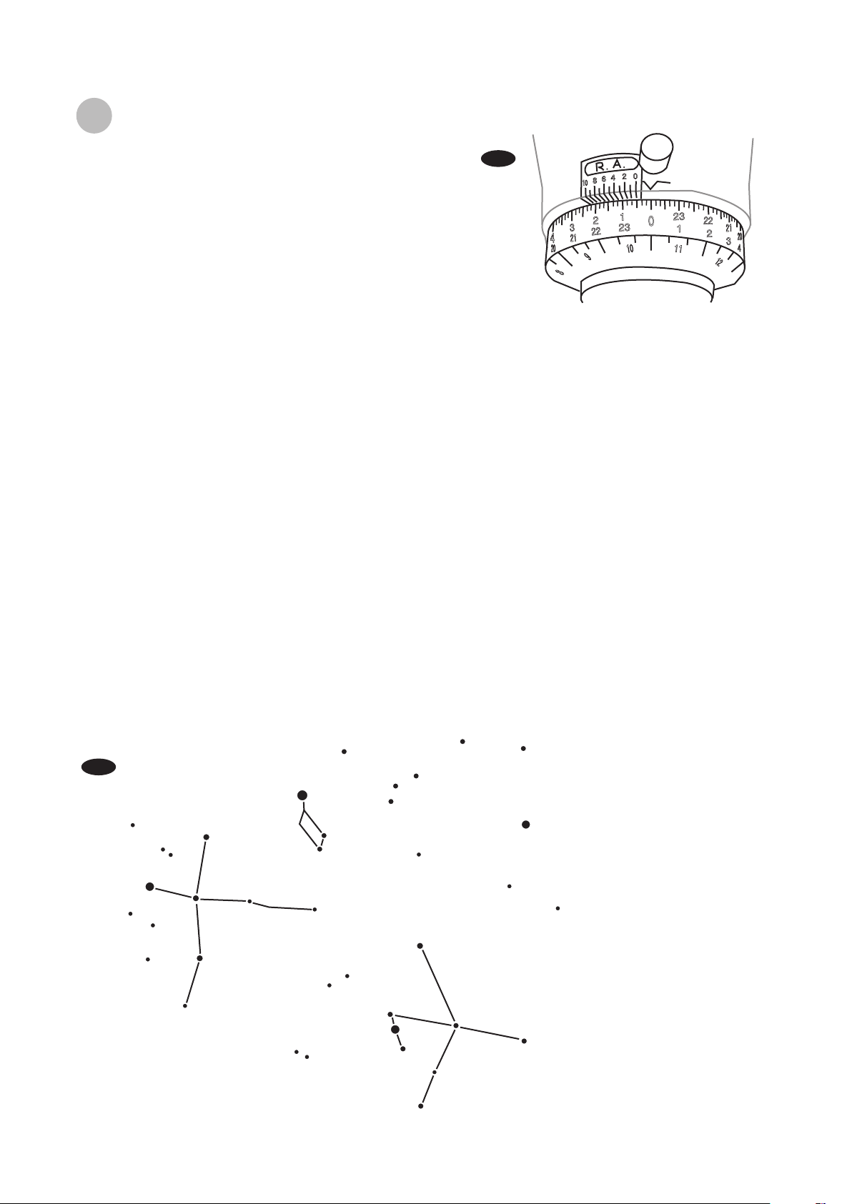
The RA setting circle is numbered from 1 to 24 in 10
minute increments. The example above shows the mount
is set to the RA coordinates of 8h 20m. The lower scale
marked 1 to 12 is the date scale. The upper scale is the
RA minute scale. Both of these can be ignored when
using the setting circle scale for finding objects.
adjustments you will need to make.
First you need to calibrate the RA axis (Fig.n). To do this align your telescope to an object with known
coordinates and then rotate the RA setting circle to show those coordinates. Leave the setscrew unlocked at this
point. Your Dec scale is factory set and does not need to be calibrated in this way. Once you are aimed at the
known object the Dec scale should have the correct coordinate reading.
Now as you rotate the scope in RA and Dec, the setting circle values change. So, to find a specific object, you
simply turn both the axes until the designated coordinates line up with the pointers on the respective scales.
After finding the object, centre it in your eyepiece, then lock the RA set screw securely. This will prevent the RA
setting from incrementing as the telescope tracks the object. You only want the RA setting circle to rotate with the
mount when you are locating objects, not when tracking them.
Let’s do an example. During summer nights the star Vega shines brightly overhead (Fig.0). Vega is easy to find
because it is so much brighter than any other stars in its general vicinity. It’s easiest to find Vega by spotting the
Summer Triangle. This is a trio of bright stars in the eastern sky consisting of Deneb (Cygnus), Altair (Aquila) and
Vega (Lyra). Vega is the westernmost of the three stars. It will be highest overhead of the three for northern
observers. Find Vega and centre it in your eyepiece.
Fig.o
Deneb
Vega
Vega is the brightest star in the
Summer Triangle, which consists of
Deneb (Cygnus), Altair(Aquila) and
Vega (Lyra). In this image Vega is at
the top. In the sky when facing east
it will be the highest of the three
stars with Deneb to its left (north)
and Altair to its lower right (south).
Altair
NE
E
SE
16
Page 17

Vega has the coordinates RA 18h 37m. With Vega centered in your eyepiece loosen the RA setting circle
setscrew and rotate the scale until it reads 18h 36m. (If you are in the Northern hemisphere use the top row of
numbers. If you are in the Southern hemisphere use the lower set of numbers.)
To do this turn the RA dial until 18 is lined up with the indicator. The small divisions are set at 10 minutes each,
so rotate another 3 divisions past 18h in the direction of 19h. This puts you at 18h 30m. Since you are aiming for
18:36, rotate about half of one more division. That will put you approximately at 18:35, and that is close enough
for visual purposes.
Now look at the Dec scale. It should be pointing at 39 degrees, which is the Declination of Vega. If it is not,
loosen the Allen screw on the Dec scale and rotate the scale until it reads 39 degrees. Retighten the Allen screw
when you are done. This will be the only time you will ever need to adjust the Dec scale.
Your mount is now calibrated on Vega and ready to point at other objects using the setting circles. Let’s try it out.
The interesting Ring Nebula (M57) is nearby at: RA 18h 52m and Dec 33 degrees. Unlock the RA scale set
screw, then unlock the RA axis and rotate the mount until the scale reads 18h 52m. Lock the RA axis but don’t
tighten the RA setscrew just yet. Now unlock the Dec axis and rotate the telescope until the Dec axis pointer is
at 33 on the scale. Lock your Dec axis.
When you look through a low power eyepiece you should be able to detect the Ring Nebula in the field of view.
Use your slow motion controls to centre it, then lock the RA setscrew by tightening it fully. When you are ready to
move on to the next object, unlock the RA set screw, then rotate the RA and Dec axes until you arrive at the
desired coordinates.
Meridian Flips
The meridian is an imaginary line that runs
directly overhead from north to south and
divides the sky into east and west (Fig.p).
You will find that any moves of the telescope
that cause you to cross the meridian will
invalidate your setting circles. If you switch
from pointing in the eastern sky to an object
in the western sky (or visa versa) you will
need to perform a meridian flip and manually
reset your RA setting circle.
The procedure for doing a meridian flip is
described in the section on pointing your
Fig.p
Right
Ascension
Equatorial Mount
(Northern Hemisphere)
Object you
are viewing
Declination
Zenith
Mount aligned on
North Celestial Pole
Polaris
telescope. If you do a meridian flip and end
up pointing at the same object you had
been viewing before, don’t forget to reset
the RA setting circle to that object’s
coordinates. If you do a meridian flip and
Meridian
Line
W
Latitude
N
point at a new object, be sure to put its
coordinates on the RA setting circle. As
always, lock down the RA set screw when
switching from finding
objects to tracking them.
S
E
It is a good idea to plan your observing so
that multiple objects in the west are viewed
in sequence before viewing objects in the
east. When viewing multiple objects on the
same side of the sky you do not need to
reset your RA setting circle as often. Why
start in the west? We recommend this
simply because objects in the western sky
will set earlier than objects in the eastern
sky. If you leave them to last, they may set
before you find them!
Plane of local horizon
17
Nadir
Apparent
movement
of stars
Plane of Celestial
Equator
Page 18

epiece
y
opriate
hoosing the app
C
Calculating the magnification (power)
The magnification produced by a telescope is determined by the focal length of the eyepiece that is used with
it. To determine a magnification for your telescope, divide its focal length by the focal length of the eyepieces
you are going to use. For example, a 10mm focal length eyepiece will give 80X magnification with an 800mm
focal length telescope.
r
e
Focal length of the telescope
magnification =
When you are looking at astronomical objects, you are looking through a column of air that reaches to the
edge of space and that column seldom stays still. Similarly, when viewing over land you are often looking
through heat waves radiating from the ground, house, buildings, etc. Your telescope may be able to give very
high magnification but what you end up magnifying is all the turbulence between the telescope and the
subject. A good rule of thumb is that the usable magnification of a telescope is about 2X per mm of aperture
under good conditions.
Calculating the field of view
The size of the view that you see through your telescope is called the true (or actual) field of view and it is
determined by the design of the eyepiece. Every eyepiece has a value, called the apparent field of view, which
is supplied by the manufacturer. Field of view is usually measured in degrees and/or arc-minutes (there are 60
arc-minutes in a degree). The true field of view produced by your telescope is calculated by dividing the
eyepiece's apparent field of view by the magnification that you previously calculated for the combination.
Using the figures in the previous magnification example, if your 10mm eyepiece has an apparent field of view
of 52 degrees, then the true field of view is 0.65 degrees or 39 arc-minutes.
True Field of View =
To put this in perspective, the moon is about 0.5° or 30 arc-minutes in diameter, so this combination would be
fine for viewing the whole moon with a little room to spare. Remember, too much magnification and too small
a field of view can make it very hard to find things. It is usually best to start at a lower magnification with its
wider field and then increase the magnification when you have found what you are looking for. First find the
moon then look at the shadows in the craters!
Focal length of the eyepiece
Apparent Field of View
=
Magnification
800mm
=
= 80X
0.65°
=
10mm
52°
80X
Calculating the exit pupil
The Exit Pupil is the diameter (in mm) of the narrowest point of the cone of light leaving your telescope.
Knowing this value for a telescope-eyepiece combination tells you whether your eye is receiving all of the light
that your primary lens or mirror is providing. The average person has a fully dilated pupil diameter of about
7mm. This value, varies a bit from person to person, is less until your eyes become fully dark adapted and
decreases as you get older. To determine an exit pupil, you divide the diameter of the primary of your
telescope (in mm) by the magnification.
Diameter of Primary mirror in mm
Exit Pupil =
For example, a 200mm f/5 telescope with a 40mm eyepiece produces a magnification of 25x and an exit pupil
of 8mm. This combination can probably be used by a young person but would not be of much value to a
senior. The same telescope used with a 32mm eyepiece gives a magnification of about 31x and an exit pupil
of 6.4mm which should be fine for most dark adapted eyes. In contrast, a 200mm f/10 telescope with the
40mm eyepiece gives a magnification of 50x and an exit pupil of 4mm, which is fine for everyone.
Magnification
18
Page 19

OBSERVING THE SKY
ky conditions
S
Sky conditions are usually defined by two atmospheric characteristics, seeing, or the steadiness of the air,
and transparency, light scattering due to the amount of water vapour and particulate material in the air. When
you observe the Moon and the planets, and they appear as though water is running over them, you probably
have bad "seeing" because you are observing through turbulent air. In conditions of good "seeing", the stars
appear steady, without twinkling, when you look at them with unassisted eyes (without a telescope). Ideal
"transparency" is when the sky is inky black and the air is unpolluted.
electing an obse
S
Travel to the best site that is reasonably accessible. It should be away from city lights, and upwind from any
source of air pollution. Always choose as high an elevation as possible; this will get you above some of the
lights and pollution and will ensure that you aren't in any ground fog. Sometimes low fog banks help to block
light pollution if you get above them. Try to have a dark, unobstructed view of the horizon, especially the
southern horizon if you are in the Northern Hemisphere and vice versa. However, remember that the darkest
sky is usually at the "Zenith", directly above your head. It is the shortest path through the atmosphere. Do not
try to observe any object when the light path passes near any protrusion on the ground. Even extremely light
winds can cause major air turbulence as they flow over the top of a building or wall.
Observing through a window is not recommended because the window glass will distort images considerably.
And an open window can be even worse, because warmer indoor air will escape out the window, causing
turbulence which also affects images. Astronomy is an outdoor activity.
hoosing the best time to obse
C
The best conditions will have still air, and obviously, a clear view of the sky. It is not necessary that the sky be
cloud-free. Often broken cloud conditions provide excellent seeing. Do not view immediately after sunset. After
the sun goes down, the Earth is still cooling, causing air turbulence. As the night goes on, not only will seeing
improve, but air pollution and ground lights will often diminish. Some of the best observing time is often in the
early morning hours. Objects are best observed as they cross the meridian, which is an imaginary line that runs
through the Zenith, due North-South. This is the point at which objects reach their highest points in the sky.
Observing at this time reduces bad atmospheric effects. When observing near the horizon, you look through
lots of atmosphere, complete with turbulence, dust particles and increased light pollution.
rving site
rve
ooling the telescope
C
Telescopes require time to cool down to outside air temperature. This may take longer if there is a big
difference between the temperature of the telescope and the outside air. This minimizes heat wave distortion
inside telescope tube (tube currents). A rule of thumb is to allow 5 minutes per inch of aperture. For example,
a 4 inch refractor would require at least 20 minutes, but an 8" reflector would require at least 40 minutes to
cool off to outside conditions. Tip: use this time for polar alignment.
yes
e
our
dapting
A
Do not expose your eyes to anything except red light for 30 minutes prior to observing. This allows your
pupils to expand to their maximum diameter and build up the levels of optical pigments, which are rapidly lost
if exposed to bright light. It is important to observe with both eyes open. This avoids fatigue at the eyepiece. If
you find this too distracting, cover the non-used eye with your hand or an eye patch. Use averted vision on
faint objects: The center of your eye is the least sensitive to low light levels. When viewing a faint object, don't
look directly at it. Instead, look slightly to the side, and the object will appear brighter.
y
19
Page 20

PROPER CARE FOR YOUR TELESCOPE
ollimating a Newtonian reflector
C
Collimation is the process of aligning the mirrors of your
telescope so that they work in concert with each other to
deliver properly focused light to your eyepiece. By
observing out-of-focus star images, you can test
whether your telescope's optics are aligned. Place a star
in the centre of the field of view and move the focuser so
that the image is slightly out of focus. If the seeing
conditions are good, you will see a central circle of light
(the Airy disc) surrounded by a number of diffraction
rings. If the rings are symmetrical about the Airy disc, the
telescope's optics are correctly collimated (Fig.q).
If you do not have a collimating tool, we suggest
that you make a "collimating cap" out of a plastic
35mm film canister (black with gray lid). Drill or
punch a small pinhole in the exact center of the lid
and cut off the bottom of the canister. This device
will keep your eye centered of the focuser tube.
Insert the collimating cap into the focuser in place
of a regular eyepiece.
Fig.q
Fig.q-1
Fig.q-2
Correctly aligned Needs collimation
Focuser
Support for
secondary mirror
Primary mirror
Secondary mirror
Primary
mirror
Collimation is a painless process and works like this:
Pull off the lens cap which covers the front of the
telescope and look down the optical tube. At the bottom
you will see the primary mirror held in place by three
clips 120º apart, and at the top the small oval
secondary mirror held in a support and tilted 45º toward
the focuser outside the tube wall (Fig.q-1).
The secondary mirror is aligned by adjusting the three
smaller screws surrounding the central bolt. The
primary mirror is adjusted by the three adjusting screws
at the back of your scope. The three locking screws
beside them serve to hold the mirror in place after
collimation. (Fig.q-2)
Aligning the Secondary Mirror
Point the telescope at a lit wall and insert the
collimating cap into the focuser in place of a regular
eyepiece. Look into the focuser through your collimating
cap. You may have to twist the focus knob a few turns
until the reflected image of the focuser is out of your
view. Note: keep your eye against the back of the focus
tube if collimating without a collimating cap. Ignore the
reflected image of the collimating cap or your eye for
now, instead look for the three clips holding the primary
mirror in place. If you can't see them (Fig.q-3), it means
that you will have to adjust the three bolts on the top of
the secondary mirror holder, with possibly an Allen
wrench or Phillip's screwdriver. You will have to
Locking screw
Fig.q-3
Primary mirror clip
Fig.q-4
Primary mirror clip
Mirror cell
Adjusting screw
Ignore the reflected
image for now
Primary mirror clip
Primary mirror clip
20
Page 21

alternately loosen one and then compensate for the slack by tightening the other two. Stop when you see
all three mirror clips (Fig.q-4). Make sure that all three small alignment screws are tightened to secure the
secondary mirror in place.
Aligning the Primary Mirror
Find the three locking screws at the back of your telescope and loosen them by a few turns.
Locking
screw
If you see 3 flat
headed screws and 3
thumbscrews, the flat
Adjusting
screw
headed screws are
the adjusting screws
and the thumbscrews
are the locking
screws.
hex bolt
(Locking screw)
Adjusting screw
If you see 3 hex bolts and 3 Phillip's head screws, the
hex bolts are the locking screws and the Phillip's-head
screws are the adjusting screws. You will need an Allen
wrench to adjust the locking screws.
Now run your hand around the front of your
telescope keeping your eye to the focuser,
you will see the reflected image of your hand.
The idea here is to see which way the primary
mirror is defected; you do this by stopping at
the point where the reflected image of the
secondary mirror is closest to the primary
mirrors' edge (Fig.q-5).
Adjusting screw
Fig.q-5
Secondary
mirror
Locking screw
If you see 3 large nuts
protruding from the back of your
telescope and 3 small
Phillip's-head screws besides
them, the Phillip's-head screws
are the locking screws and the
large nuts are the adjusting
screws.
When you get to that point, stop and keep
your hand there while looking at the back end
of your telescope, is there an adjusting screw
there? If there is you will want to loosen it
(turn the screw to the left) to bring the mirror
away from that point. If there isn't an adjusting
screw there, then go across to the other side
and tighten the adjusting screw on the other
side. This will gradually bring the mirror into
line until it looks like Fig.q-6. (It helps to have
a friend to help for primary mirror collimation.
Have your partner adjust the adjusting screws
according to your directions while you look in
the focuser.)
After dark go out and point your telescope at
Polaris, the North Star. With an eyepiece in
the focuser, take the image out of focus. You
will see the same image only now, it will be
illuminated by starlight. If necessary, repeat
the collimating process only keep the star
centered while tweaking the mirror.
Primary mirror
Fig.q-6
Both mirrors aligned
with collimating cap in
stop and keep your
hand here
Both mirrors aligned with
eye looking in focuser
21
Page 22

ollimating a refractor with the adjustable objective-lens cell
C
Collimation is the process of aligning the lenses of your
telescope so that the light they collect will focus at the right spot
at the back of your telescope for your eyepieces to work.
Collimation is a simple process and works like this:
Pull off the dew cap at the front of your telescope and look into
the scope. The pair of lenses are held in a cell by a threaded
ring. This cell is held in place by three pairs of screws spaced
120 degrees apart. The larger Phillip's head screws actually
hold the cell on, while the smaller, buried Allen screws push
against a ledge at the front of the tube and allow the cell to tilt
slightly, by tension against the Phillips screws (Fig.r). The idea
is to alternately loosen and tighten each against the other until
you have a round star image.
There are a number of devices available for collimation. One of
the best is your eyepiece and Polaris. For this purpose it is best
that your telescope not be polar aligned, in fact point the mount
head due east or west.
Use your lowest power (largest number) eyepiece to acquire
Polaris, place it in the center of the eypepiece view. Now switch
to your next higher power eyepiece, while keeping the image
centered. The in-focus star image will have a bright innermost
point, a slightly fainter inner ring and a fainter still outer ring that
is hard to see (Fig.r-1). If it doesn't look like this, or you can't
reach focus then start with: take out your star diagonal and look
at the image slightly out of focus, this will allow you to gauge
the deflection. A typical off-collimation image will have a bright
spot off to one side when you bring the focus out (Fig.r-2).
The actual process is to slightly loosen the pair on the side the
deflection is, slacken the Allen head screws then tighten the
Phillip's head screws against them again. Check the star image
again after moving it into the centre of the eyepiece. If you find
your image getting worse, then go the other way, or slacken the
other two Allen screws a little. Once you have a round star
image you are set.
Fig.r
Fig.r-1
Correctly aligned
Fig.r-2
It helps to have a friend to help with the collimation.
Needs collimation
Have your partner adjust the screws according to your
directions while you look in the eyepiece.
leaning your telescope
C
Replace the dust cap over the end of the telescope whenever it is not in use. This prevents dust from
settling on the mirror or lens surfaces. Do not clean the mirror or lens unless you are familiar with optical
surfaces. Clean the finderscope and eyepieces with special lens paper only. Eyepieces should be
handled with care, avoid touching optical surfaces.
22
Page 23

APPENDIX A - PRECISE POLAR ALIGNMENT
FOR NORTHERN HEMISPHERE
When your equatorial mount is polar-aligned it is able track the sky easily and hold targets in the eyepiece with
just occasional adjustments to the RA control cable. If your mount is motorized it can hold objects in the
eyepiece almost indefinitely. An accurate polar alignment also greatly reduces the number of guiding
corrections that are needed during long exposure astrophotography.
However, for all but the most critical photographic applications, your polar alignment does not need to be
perfect. Your mount will provide excellent performance even if there is some error in the polar alignment.
SkyWatcher has developed user-friendly equipment and procedures to minimize such errors, and this
makes an adequate polar alignment easy to accomplish.
PREPARING THE MOUNT
Aligning the polar scope reticule
The polar scope needs to be aligned with the polar axis of your mount. The steps below tell you how to perform
this alignment. Note, you can do this procedure at night while pointing at Polaris. However, it is probably easier
to do it in the daytime using a distant point as your target (e.g, a street light a couple of hundred yards away). If
doing the procedure during the day, you might find it convenient to set your altitude to near parallel with the
ground to put the eyepiece of the polar scope into a comfortable position. Just be sure to leave room to make
vertical adjustments in both directions. Also, do this procedure without a telescope or counterweights attached. It
will make turning the mount a lot simpler.
1.
Locate a distant object and place it under the cross at the
centre of the polarscope reticule.
Fig.s-1
If target drifted to here
2
Rotate the mount in RA 180 degrees (i.e., 12 hours on the RA
setting circle).
3.
Note the displacement of your target from the centre of the
crosshairs (Fig.s-1). If it is not displaced at all, it means your
polar scope reticule is already properly aligned and you don't
need to do any more. If it is displaced, continue with the next
step of the alignment procedure.
4.
Use the three adjustment screws on the polar scope to move
the reticule so that exactly one-half of the displacement is
corrected for. For example, if the displacement were about
half an inch in the direction of 1 o'clock, then you would adjust
the cross at the centre of the reticule to go half the distance in
that direction (Figure s-2).
5.
Now continue to move the cross using the altitude and
azimuth adjusters on the mount. When the target is back
under the cross, go back to step 2, but this time rotate the
mount 180 degrees in the opposite direction. If you still get
displacement of the target, repeat steps 3-5.
Setting your latitude
One bolt should always be loose when doing adjustments.
Gently tighten both bolts when your adjustment is complete.
adjust reticule to
place it here (half
the distance)
Fig.s-2
Remove the caps from the upper and lower ends of the RA axis so you can look into the polar scope. Adjust the
north and south T-bolts on the mount so the latitude indicator points to your local latitude (Fig.2). Look through
the polar scope and adjust the azimuth and altitude controls as needed so that Polaris appears in the view of the
polar scope. Once you see it you can use one of the simplified procedures below to place Polaris at the correct
position for an accurate polar alignment.
I
Page 24

SIMPLIFIED POLAR ALIGNMENT PROCEDURES
The NEQ3 and EQ5 mounts have specially designed reticule patterns and simplified procedures to make polar
aligning your mount very simple. In fact, if you purchased a SynScan equipped mount you can perform an
extremely accurate polar alignment in less than two minutes! See the SynScan User manual for details.
If you do not have a SynScan mount you can still get a very good alignment without much bother. The two
simple procedures detailed below work equally well. Use whichever one you like best.
Pattern-based method
Northern Hemisphere - Identify the Big Dipper pattern in the constellation Ursa Major, or find the constellation
Cassiopeia in the night sky. In spring and summer, the Big Dipper will be higher in the sky and easier to find. In
fall and winter, Cassiopeia may be easier to use.
The patterns for both are etched on your polar scope reticule
(Fig.S-3). Simply rotate your mount in RA until one of the
patterns matches its actual orientation in the sky. Lock the RA
axis. Now the small circle on the perimeter of the larger circle
is in the correct position for locating Polaris.
Next, use your azimuth and altitude adjustment controls to
place Polaris inside the small circle. Tighten your azimuth and
altitude knobs, then tighten your locking shaft bolt to secure
the mount to the tripod and you are done.
Pattern-based method
Kochab is the brightest star in the bucket portion of the Little
Dipper (Fig.S-4). It also happens to form a line with Polaris and
the North Celestial Pole (NCP) - the point in space at which you
want to aim your polar axis to achieve an accurate polar
alignment. Kochab rotates around the NCP the way the hour
hand rotates around a clock face, but it takes Kochab nearly 24
hours to make one revolution. We can use this behavior to help
us achieve an accurate polar alignment quickly and simply.
First, identify the bright star Kochab in the bucket of the Little
Dipper. Now look at Polaris and imagine it is the center of a
clock face. Take note of what “time” Kochab appears. For
example, if Kochab were directly to the right of Polaris, it
would be at 3 o’clock. In the figure above, it is at about 8:00.
Fig.s-3
B
i
g
D
i
p
p
e
r
Fig.s-4
10
Polaris
11
Octans
NCP
12
a
i
e
p
o
i
s
s
a
C
1
2
Now look into your polar scope. Rotate your mount in RA to
place the Polaris indicator circle at the time indicated by
Kochab clock method. Then, use your altitude and azimuth
adjustment controls to put Polaris inside the circle. Tighten
your controls and your locking shaft bolt and you are done.
Southern Hemisphere
There is a 4-star pattern in the polar scope, which resembles
the bucket of the Big Dipper. In the Southern Hemisphere,
there is an Asterism in Octans, which has this shape. By
rotating the R.A. axis and by adjusting the altitude and
azimuth of the mount, the four stars in the Asterism can be
placed in the circles in the Pole Finder. This procedure can be
somewhat difficult in the city because all four of these stars
are fainter than Magnitude 5.
II
Polaris
9
Kochab
8
7
6
Kochab is the brightest star in the bucket of
the Little Dipper. Other stars in the region
are quite dim and are not drawn here.
3
4
5
Page 25

APPENDIX B - OPTIONAL ACCESSORIES
NEQ3 & EQ5 SYNSCAN
Sky-Watcher offers simple solutions for users who would like
to attach their smaller telescope to a convenient computerized system but do not wish to deal with the weight of the
HEQ5 or EQ6 mount. The NEQ3 and EQ5 SynScan mounts
use the same Go-To system found in the HEQ5 and EQ6 Pro
mounts. It allows you to point the telescope at a specific
object or even tour the skies at the touch of a button.
DUAL AXIS MOTOR DRIVES
The EQ3 dual axis motor drives precisely control the
telescopes’ tracking speed to compensate for the earth's
rotation. Available in 2x, 4x, and 8x speeds through the Hand
Controller. These DC motor drives run on 4 "D" cell batteries
(not included). Motors for both axes, clutches, cables, hand
controller, and battery case are included.
SINGLE AXIS MOTOR DRIVE
These single axis (R.A.) DC motor drives are powered by 4
"D" cell batteries (not included). A set of batteries will allow
several nights of observing. 2x and 8x tracking speeds (2x
and 4x for EQ1 model) are available through the hand controller. Motor, hand controller, and battery case are included.
COLLIMATING EYEPIECE
The Sky-Watcher Collimation Eyepiece is ideal for precise
collimation of Newtonians and refractors with an adjustable
lenscells. This special eyepiece fits into 1¼" focusers or
diagonals. Alignment is easy using the small opening on one
end and thin crosshairs at the other end.
WIDE-ANGLE EYEPIECES
These Sky-Watcher Wide Angle Eyepieces offer a generous
66° apparent field of view, allowing more sky to be viewed at
one time. They provide sharp image right across the field.
The rubber eyecups are included for viewing comfort and to
keep out extraneous light.
Focal Lengths: 20mm, 15mm, 9mm, 6mm
Eyepiece Barrels: 1.25"
Eye-relief: 14.8mm (W6), 15mm (W9), 13mm (W15), 18mm
(W20)
DUAL FLASHLIGHT
These multipurpose flashlights provide instant switch between
the night vision protecting red light and regular white light. A
convenient control wheel is available for brightness adjustment.
III
Page 26

mateur
A
APPENDIX C - RECOMMENDED READING
Astronomy
stro-photography
A
Beginner's Guide to Amateur Astronomy: An
Owner's Manual for the Night Sky by David J.
Eicher and, Michael Emmerich (Kalmbach
Publishing Co., Books Division, Waukesha,
WI, 1993).
NightWatch: A Practical Guide to Viewing the
Universe by Terence Dickinson, (Firefly Books,
Willowdale, ON, Canada, 3rd edition, 1999).
Star Testing Astronomical Telescopes by
Harold Richard Suiter, (Willmann-Bell, Inc.,
Richmond, VA, 1994).
Star Ware: The Amateur Astronomer's Ultimate
Guide to Choosing, Buying, and Using
Telescopes and Accessories by Philip S.
Harrington (John Wiley & Sons, New York,
1998).
The Backyard Astronomer's Guide by Terence
Dickinson and Alan Dyer (Firefly Books Ltd.,
Willowdale, ON, Canada, revised edition,
1994).
The Great Atlas of the Stars by Serge Brunier,
Constellation photography by Akira Fujii (Firefly
Books; Willowdale, ON, Canada 2001).
A Manual Of Advanced Celestial Photography
by Brad D. Wallis and Robert W. Provin
(Cambridge University Press; New York; 1984).
Astrophotography An Introduction by H.J.P.
Arnold (Sky Publishing Corp., Cambridge,
MA,Sky & Telescope Observer's Guides Series,
ed. Leif J. Robinson, 1995).
Astrophotography for the Amateur by Michael
Covington (Cambridge University Press,
Cambridge, UK, 2nd edition,1999).
Splendors of the Universe: A Practical Guide to
Photographing the Night Sky by Terence
Dickinson and Jack Newton (Firefly Books,
Willowdale, ON, Canada, 1997).
Wide-Field Astrophotography by Robert Reeves
(Willmann-Bell, Inc., Richmond, VA, 2000).
The Beginner's Observing Guide: An
Introduction to the Night Sky for the Novice
Stargazer by Leo Enright, (The Royal
Astronomical Society of Canada, Toronto, ON,
Canada, 1999).
The Deep Sky: An Introduction by Philip S.
Harrington (Sky Publishing Corporation,
Cambridge, MA, Sky & Telescope Observer's
Guides Series, ed. Leif J. Robinson, 1997).
The Universe from Your Backyard: A Guide to
Deep Sky Objects by David J. Eicher
(Kalmbach Publishing Co., Books Division,
Waukesha, WI, 1988).
Turn Left at Orion: A Hundred Night Sky
Objects to See in a Small Telescope--and how
to Find Them by Guy J. Consolmagno and
Dan M. Davis, (Cambridge University Press,
New York, 3rd edition, 2000)
bservational References
O
A Field Guide to the Stars and Planets by Jay
M. Pasachoff, (Houghton Mifflin Company,
1999).
Atlas of the Moon by Antonín Rükl (Kalmbach
Publishing Co., Books Division, Waukesha,
WI, 1993).
Burnham's Celestial Handbook: An Observer's
Guide to the Universe Beyond the Solar
System by Robert Burnham (Dover
Publications, New York; 3- volume set, 1978).
Observer's Handbook by The Royal
Astronomical Society of Canada, (University of
Toronto Press, Toronto, ON, Canada,
published annually).
Sky Atlas 2000.0 by Wil Tirion and Roger W.
Sinnott (Sky Publishing Corp., Cambridge, MA,
2nd edition, 1998).
IV
Page 27
Page 28

EQ5 SynScan INSTALLATION
CONTENTS
Hand Control Cable
Hand Control
Hand Controller
Motor Controller
holder
Motor Controller
SETTING UP
1)
Locate the hand control holder. Slide the
holder onto the accessory tray as shown in
Fig.1.
2)
Point the mount to the North, or South in the
Southern Hemisphere. Clip the motor
controller holder onto the leg that's on the
right hand side of the mount, as seen in
Fig.2.
3)
Slide the motor controller into the holder, as
seen in Fig.3
4)
Rotate the mount in Dec axis so that the Dec
motor is on the same side of the receptacles
of the mount, as seen in Fig.4.
Power Cord
Motor Cables
Hand Control
Holder
Auto Guide
DC 12V
Fig.1
Fig.3
Fig.2
Fig.4
To avoid potential electronic-magnetic interference
to other devices, the motor controller holder must be
clipped firmly onto the stainless leg and the motor
CONNECTING THE CABLES
5)
Locate the short motor cable. Plug one end
of the cable into the motor controller, and the
other into the the receptacle labeled "R.A.
In" on the mount. (Fig.5)
6)
Locate the long motor cable. Plug one end
of the cable into the motor on the Dec axis,
and the other into the receptacle labeled
"Dec. out" on the mount. (Fig.6)
7)
The hand control cable has a RJ-45
connector on both ends. Plug one end into
the hand control and the other into the outlet
on the mount.
8)
Locate the power cord. Make sure that the
power switch on the motor controller is OFF.
Plug the cigarette lighter end of the cable
into the battery and the other into the motor
controller.
Fig.5
Hand Controller
Dec.
OUT
R.A.
Hand Controller
DC 12V
Auto Guide
Fig.6
DC 12V
Auto Guide
IN
Dec.
OUT
R.A.
IN
191206V1
Page 29
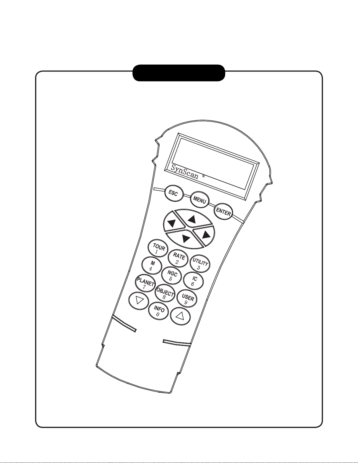
INSTRUCTION MANUAL
TM
SynScan
Copyright © Sky-Watcher
140303V4
Page 30

CONTENT
CONTENT
Basic Operations
PART I : INTRODUCTION
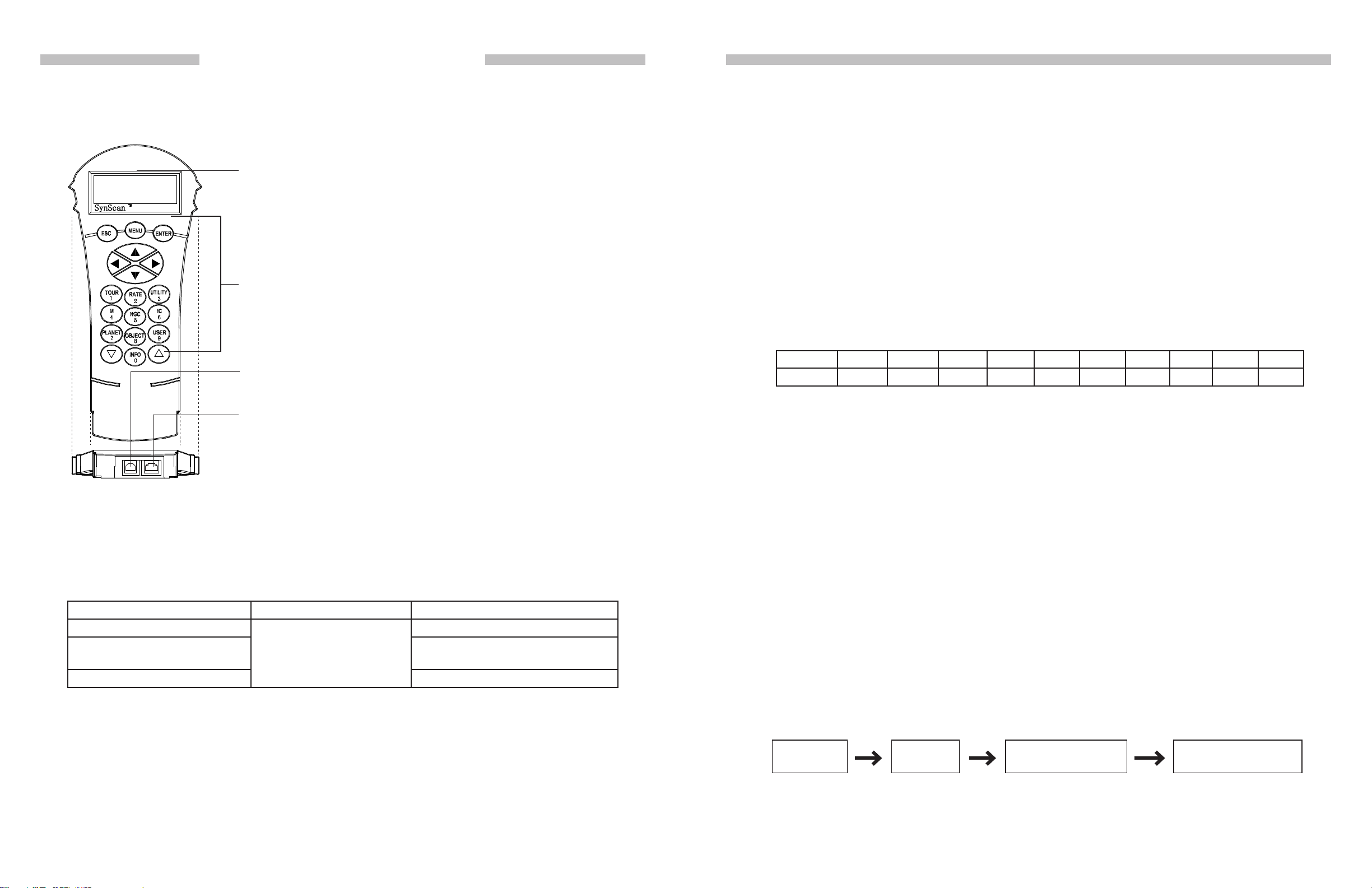
1.1 Outline and Interface .......................................................................................... 4
1.2 Connecting to a Telescope Mount ...................................................................... 4
1.3 Slew the Mount with the Direction Keys .............................................................. 4
1.4 SynScan Hand control’s Operating Modes .................................................... 5
PART II : INITIALIZATION
2.1 Setup Home Position of the Telescope Mount ..................................................... 7
2.2 Initialize the Hand Control .................................................................................. 7
PART III : ALIGNMENT
3.1 Choosing an Alignment Method .........................................................................10
3.2 Aligning to Alignment Stars ...............................................................................10
3.3 Alignment Method for Equatorial Mounts ..........................................................10
3.4 Alt-Azimuth Mounts using Brightest Star Alignment Method ............................11
3.5 Alt-Azimuth Mounts using 2-Star Alignment Method ........................................12
3.6 Tips for Improving Alignment Accuracy .............................................................15
3.7 Comparison of Alignment Methods ....................................................................15
PART IV : SYNSCAN MENU TREE
4.1 Menu Structure .................................................................................................. 17
4.2 Accessing Menus ..............................................................................................18
4.3 Short-cut Keys ....................................................................................................18
PART V : LOCATING OBJECTS
5.1 Locating Messier Objects ................................................................................. 19
5.2 Locating NGC and IC Objects .......................................................................... 20
5.3 Locating Planets and the Moon ........................................................................ 20
5.4 Locating Caldwell Objects ................................................................................ 20
5.5 Locating SAO Stars .......................................................................................... 21
5.6 Locating Named Stars, Double Stars, and Variable Stars ............................... 21
5.7 Deep Sky Tour ................................................................................................... 22
5.8 User-Dened Objects ........................................................................................ 22
PART VIII : AUXILIARY FUNCTIONS
8.1 Editing Date, Time, Coordinates, Time Zones, and Daylight Saving Time ......... 27
8.2 Re-aligning the Mount ........................................................................................ 27
8.3 Show Position ................................................................................................. 27
8.4 Show Time and Local Sidereal Time ............................................................ 27
8.5 Display Version Information ........................................................................... 27
8.6 Display Power Voltage ................................................................................... 28
8.7 Display Polaris Position .................................................................................. 28
8.8 Display Polar Alignment Error ........................................................................ 28
8.9 Changing Polar Scope Illumination Level ..................................................... 28
8.10 Identifying Objects ............................................................................................. 28
8.11 Synchronizing Encoders .................................................................................... 29
Advanced Operations
PART IX : CONNECTING TO A COMPUTER
9.1 Working with Astronomical Applications .............................................................. 30
9.2 PC Direct Mode ..................................................................................................30
PART X : UPDATING FIRMWARE
10.1 Hardware Requirements .................................................................................... 31
10.2 Preparation ........................................................................................................ 31
10.3 Updating Firmware ............................................................................................. 31
10.4 Trouble Shooting ............................................................................................... 32
PART XI : ADVANCED FUNCTIONS
11.1 Parking Telescope .............................................................................................. 33
11.2 Pointing Accuracy Enhancement ........................................................................ 34
11.3 Polar Alignment without Polar Scope ............................................................... 35
11.4 Camera Control .................................................................................................. 36
11.5 Periodic Error Correction (PEC) for EQ Mount ..................................................... 38
11.6 Calibrating Auto-Home Offset ............................................................................ 39
Intermediate Operations
PART VI : CONFIGURE THE TELESCOPE MOUNT
6.1 Choosing Tracking Speed ...............................................................................24
6.2 Backlash Compensation ...................................................................................24
6.3 Setting the Slewing Limits ..............................................................................24
6.4 Enable/Disable Auxiliary Encoder ....................................................................25
6.5 Setting Autoguider Speed ................................................................................25
PART VII : CONFIGURE THE HAND CONTRL
7.1 Display, Keypad ................................................................................................. 26
7.2 Alignment Star Filter ........................................................................................... 26
7.3 Sorting Method of the Alignment Star List ......................................................... 26
7.4 Naming of Stars ................................................................................................ 26
PART XII : USING A SYNSCAN GPS MODULE
12.1 Initialization of the Hand control with a SynScan GPS Module .......................... 40
12.2 Checking GPS Information .................................................................................. 40
Appendix
APPENDIX I : ELIMINATING CONE ERROR ...................................................... 41
APPENDIX II : SYNSCAN SELF-DIAGNOSIS ..................................................... 42
APPENDIX III : SCHEMATIC OF THE PORTS .................................................... 43
APPENDIX IV : SPECIFICATIONS ................................................................ 43
2 3
Page 31
PART I : INTRODUCTION
PART I: INTRODUCTION
1.1 Outline and Interface
A SynScan hand control and its interfaces are shown in Fig. 1.1
LCD Display Screen: It can display two lines of text, 18 characters
per line. The contrast and the brightness of the red backlight are adjustable.
Buttons: ESC, MENU, ENTER, directional, number/shortcut keys,
and scroll keys.
Multi-Purpose Port: Connects to an external device such as a computer, a GPS module, a camera, etc.
Mount Port: Connects to a Sky-Watcher telescope mount. The hand
control can get power supply from the mount via this port.
• The left and right keys are used to control the movements of the Right Ascension (R.A.)
axis (for an equatorial mount) or the azimuth axis (for an Alt-azimuth mount).
• The up and down keys are used to control the movements of the Declination (Dec.) axis
(for an equatorial mount) or altitude axis (for an Alt-azimuth mount).
• In most cases, pressing the “RATE/2” key will invoke the operation of choosing a slewing
speed:
» The LCD screen will display “Set Speed”, followed by the current speed as “Rate = *x”’.
» Press a number between “0” and “9” to select a new speed.
» Press the ENTER key to return to the previous display.
» If the user does not press the ENTER button, he/she can continue to change the speed
while using the direction keys to slew the mount.
» If there is no keypad operation in 5 seconds, the most recent speed will be kept and
the LCD display will return to the previous ones.
• The following table lists the available speeds:
Rate 0 1 2 3 4 5 6 7 8 9
Speed *10.5X
*2
1X
*3
8X 16X 32X 64X 128X 400X 600X Max
*4
• Rate 7/8/9 is primarily used to quickly slew a mount.
• Rate 5/6 is primarily used to move a target in the eld of view of a nder scope.
Fig. 1.1
1.2 Connecting to a Telescope Mount
Connect the 8-pin (RJ-45) “Mount” port of the hand control to the “Hand Control” port on a
Sky-Watcher mount using an appropriate cable. The table below lists the “Hand Control” ports
on different Sky-Watcher mounts.
Mount Model Hand control Port “Hand Control” Port on Mount
EQ6 Pro
HEQ5 Pro, EQ5 Pro, EQ3 Pro,
AZ-EQ6 GT, EQ8
All Alt-azimuth mounts 6-pin RJ-12
8-pin RJ-45
D-sub 9 Male
8-pin RJ-45
1.3 Slew the Mount with the Direction Keys
In many situations, users need to slew the mount at different speeds with the directional keys.
Here are the guides for this operation:
• Rate 2/3/4 is primarily used to move a target in the eld of view of an eyepiece.
• Rate 0/1 is used to move a target in the eld of view in high magnication observations,
or manual-guiding.
Note:
*1: Speed is represented as multiples of the Earth’s rotation speed.
*2, *3: For Equatorial mounts, the speed is the drift speed of an object in FOV while the mount’s
tracking is turned on; it is not the axis’s rotation speed.
*4: Maximum speed varies on mounts. For most Sky-Watcher mounts, it is higher than 800X
(3.4 degrees/sec).
1.4 SynScan Hand control’s Operating Mode
The SynScan hand control has 2 operating modes: Full Feature Mode and Easy Tracking
Mode.
1. Full Feature Mode:
The ow chart of the “Full Feature” operation is shown in Fig. 1.4a.
Initialization Alignment
Locate a celestial
object automatically
Observing or other
operations
4 5
Fig. 1.4a
Page 32

PART I: INTRODUCTION
PART II : INITIALIZATION
In Full Feature mode, the hand control must connect to a Sky-Watcher telescope mount.
After turning on the power to the mount, the hand control must complete an “Initialization”
routine, followed by an “Alignment” routine which establishes a model to transform the
coordinates of the mount and the coordinates of the sky. Only after the “Alignment” is
done can the SynScan hand control’s high precsion “GOTO” function be used to locate a
celestial object.
The Full Feature mode is the most commonly used mode of operation.
2. Easy Tracking Mode:
The ow chart of the “Easy Tracking” operation is shown below:
Initialization
In Easy Tracking mode, the hand control also needs to connect to a Sky-Watcher telescope mount. The mount must be setup at a proper “Home Position” (refer to Section 2.1
for details) before turning on the power. After turning on the power of the mount, the hand
control must complete an “Initialization” routine. Then the user can choose to skip the
“Alignment” routine and start the tracking function directly (refer to Section 6.1 “Choosing
Tracking Speed”). Users will need to locate a celestial object in the sky, and then use the
hand control to manually point the telescope to the target. The object locating function may
still be used but it can only give a rough result.
Start Tracking
Locate a celestial
object manually
Observing or other
operations
Fig. 1.4b
2.1 Setup Home Position of the Telescope Mount
Before powering on the telescope mount, it should be setup to a particular home position. The
home position differs between an equatorial mount and an Alt-azimuth mount.
1. Home Position of an Equatorial Mount:
• Tripod head is leveled.
• R.A. axis points towards the Northern Celestial Pole (in Northern Hemisphere) or the
Southern Celestial Pole (in Southern Hemisphere).
• Counterweight rod is at its lowest position.
• The telescope points towards the Northern Celestial Pole (in Northern Hemisphere) or
the Southern Celestial Pole (in Southern Hemisphere).
2. Home Position of an Alt-azimuth Mount:
To operate the SynScan hand control in “Full Feature” mode, no particular home position
is required.
To operate the SynScan hand control in “Easy Tracking” mode, the mount should be setup
as close to home position as possible, according to the following instuctions:
• Mount base is leveled.
• The telescope’s tube is leveled and points towards the true North (note: not magnetic
North).
2.2 Initialize the Hand Control
Once the mount has been setup to the home position, the user can turn on the power to the
mount and start the initialization process on the SynScan hand control. The following is the
steps:
The Easy Tracking mode is suitable for quick setup for visual observing of brighter celestial
objects, such as planets, the moon, or the sun. If the user does not turn on the tracking
function, the Easy Tracking mode can also be used for observing terrestrial objects.
1. Selecting the Operation Mode of the Mount
A SynScan hand control with a rmware version 4.05.06 or later supports both an equatorial mount and an alt-azimuth mount. It is able to detect the model of the mount to which it
connects and select the appropriate operation mode accordingly.
For an equatorial/Alt-azimuth dual-mode mount, such as the AZ-EQ6 GT mount, the SynScan hand control will require the user to choose the mount’s operating mode.
• The LCD screen will display “Operating Mode” in the rst line.
• Use the scrolling keys located at the bottom left and right of the keypad to choose be-
tween Equatorial mode (EQ Mode) and Alt-azimuth mode (AZ Mode).
• Press ENTER to conrm the selection.
2. Firmware Version Display
The hand control will display the rmware version.
• Press ENTER to proceed to the next step. Press ESC to return to the previous step.
• Users can slew the mount with direction keys in this step.
6 7
Page 33

PART II: INITIALIZATION
PART II: INITIALIZATION
3. Warning Message Conrmation
The hand control will display a warning message about the dangers of viewing the sun with
a telescope.
• Press ENTER to conrm you have read the warning messages and proceed to the next
step. Press ESC to return to the previous (rmware version display) step.
• Users can slew the mount with direction keys in this step.
4. Auto-homing (EQ8 Only)
This step only applies to a mount with Auto-homing feature (such as the Sky-Watcher EQ8
Equatorial mount).
• The LCD screen will display “Auto-Home?” in the rst line, and display “1) YES 2) NO”
in the second line.
• Press “2” to skip this step and proceed to the next step.
• Press “1” to start the auto-homing routine on the mount. Once complete, the screen will
display “Home Position Established”. Press ENTER to proceed to the next step.
• During auto-homing routine, pressing the ESC key will stop the mount’s movement. The
screen will display “Home Position NOT Established.” Press ENTER to proceed to the next
step.
5. Setting Information of the Observing Site
Geographic Coordinates
The LCD screen will display “Set Longitude” or “Set Latitude“ in the rst line, and display
longitude and latitude in the second line.
• Press the numeric keys at the cursor position to ll the longitude or latitude digits.
• Use the scroll keys to change east/west longitude or north/south latitude when the cur-
sor blinks on the corresponding characters (E/W for longitude, N/S for latitude).
Date, Time, Daylight Saving Time
• When “Date: mm/dd/yyyy” is displayed, enter the current date in the indicated mm/dd/
yyyy format (i.e. 10/24/2012 for Oct.24,2012); press the ENTER key to conrm and pro-
ceed to the next step. Press the ESC key to return to the “Geographic Coordinates” step.
• When “Enter Time” is displayed, enter the current local time in 24-hour format. (i.e.
18:30:00 for 6:30pm). Press the ENTER key to display the entered time in 12-hour for-
mat. Press the ENTER key again to conrm and proceed to the next step. Press the ESC
key to return to the previous step.
• When “Daylight Saving?” is displayed, use the scroll keys to select “Yes” or “No”. “YES”
indicates the time entered in the previous step is daylight saving time, while “NO” indicates the time entered is in standard time. Press the ENTER key to conrm and proceed
to the next step. Press the ESC key to return to the previous step.
6. Display Polaris Position
This step applies to an equatorial mount only.
• The LCD screen will display “Polaris Position in P.Scope = HH:MM”. It tells the orienta-
tion of Polaris in the polar-scope’s FOV. User can imagine the large circle in the FOV
of a polar-scope as a clock’s face with 12:00 at the top, and put Polaris at the “HH:MM”
position of the large circle when using a polar-scope to do the polar alignment. Press
ENTER key to conrm and proceed to the next step. Press ESC key to return to the pre-
vious step.
• The LCD screen will display “Hour Angle of Polaris = HH:MM“. Press ENTER key to
conrm and proceed to the next step. Press ESC key to return to the previous step.
7. Starting Mount Alignment
This is the last step in the hand control’s initialization process. The screen will display “Be-
gin Alignment? 1) YES 2) NO” to ask the user to make a choice:
• Use the Left and Right direction keys to move the cursor.
• Press the ENTER key to conrm the input and proceed to the next step.
• Press the ESC key to return to the previous.
Time Zone
The LCD screen will display “Set Time Zone” in the rst line, and display the current time
zone in the second line.
• Use the scroll keys to change the leading “+” or “-” sign when the cursor is on it. The “+”
sign is used for time zones in the Eastern Hemisphere (Europe, Africa, Asia, Oceania),
while the “-” sign is used for time zones in the Western Hemisphere (North and South
America).
• Press the numeric keys at the cursor position to ll the time zone digits.
• Press the ENTER key to conrm the input and proceed to the next step.
• Press the ESC key to return to the previous step.
8 9
Press “1” to start the alignment process
The SynScan hand control will operate in Full Feature mode (ref er t o Section 1.4) after the
alignment.
Press “2” to skip the alignment process.
The SynScan hand control will enter standby mode.
• Users may start the tracking functions (ref er t o Section 6.1), or use the GOTO function
(ref er to PART V) to roughly locate celestial objects. Both operations will let the SynScan
hand control work in the Easy Tracking mode (refer to Section 1.4 Step 2).
• Users can also start an alignment process (refer to Section 8.2) to let the SynScan
hand control operate in Full Feature mode.
• Users may slew the mount with the direction keys to point the telescope to terrestrial
targets for observing. The “User-Dened Objects” function (refer to Section 5.8) of the
SynScan hand control is a useful tool for terrestrial observing.
Page 34

PART III : ALIGNMENT
PART III : ALIGNMENT
3.1 Choosing an Alignment Method
At the beginning of the alignment process, users are asked to choose an alignment method.
The available alignment methods differ between the mount types, as listed below:
• For an equatorial mount: 1-Start Alignment (1-Star Align.), 2-Star Alignment (2-Star
Align.) or 3-Star Alignment (3-Star Align.)
• For an alt-azimuth mount: Brightest Star Alignment (Brightest Star) or 2-Star Alignment
(2-Star Align.)
Note: For a detailed description and comparison of each alignment method, please refer to
Section 3.7.
Operation:
• The LCD screen displays “Alignment:” in the rst line.
• Use the two scrolling keys to select an alignment method in the second line of the LCD
screen.
• Press ENTER to conrm selection and proceed to the next step (Section 3.2).
• Press ESC to skip the alignment process and enter standby mode.
3.2 Aligning to Alignment Stars
In this step, user will be asked to choose one or multiple alignment stars from a list provided
by the SynScan hand control, and then control the mount to center the star(s) in the FOV of
the telescope’s eyepiece. The SynScan hand control will then use the data collected in this
process to transform between the mount coordinates and the sky coordinates.
The operating steps of aligning to alignment stars may differ depending on the type of mount
used, as well as the chosen alignment method. Users should read the following section which
meets your mount and alignment method:
• Section 3.3: Alignment Method for Equatorial mounts.
• Section 3.4: Alt-azimuth mounts using the Brightest Star Alignment method.
• Section 3.5: Alt-azimuth mounts using the 2-Star Alignment method.
3. Now users can use the direction keys to move the telescope to align with the 1
st
alignment
star. That is, center the 1st alignment star in the FOV of the nder scope, and then center
it in the FOV of the telescope’s eyepiece; press ENTER key to conrm centering of the star
and proceed to the next step. Generally, users can use Rate 5 or 6 to center the star in the
nder scope and use Rate 2 or 3 to center the star in the telescope’s eyepiece.
4. If the user has chosen 1-Star Alignment method before, the SynScan hand control will now
display “Alignment Successful”. Press ENTER to complete the alignment process.
5. If the user has chosen 2-Star Alignment or 3-Star Alignment before, the SynScan hand
control will then proceed to the next step.
Aligning the 2
1. Again, the SynScan hand control asks the user to choose and align a 2
nd
Star:
nd
alignment star.
The operation is the same as that of aligning the 1st alignment star.
2. If the user has chosen 2-Star Alignment before, the SynScan hand control will display
“Alignment Successful” after conrmation of centering the 2nd alignment star.
3. Two seconds later, the LCD screen will display the polar-alignment offset of the mount. The
“Mel” value is the offset in elevation, and the “Maz” value is the offset in azimuth.
4. If the user has chosen 3-Star Alignment before, the SynScan hand control will then pro-
ceed to the next step.
Selecting and Aligning the 3
rd
Star:
The operation is the same as that of Aligning the 2nd Star.
Cancellation During Aligning Process:
1. While the mount is slewing during the alignment, users may press the ESC key to stop the
mount. The hand control screen will display “MOUNT STOPPED!!. Press any key…”
2. Press any key and the SynScan hand control will ask the user to select another alignment
star.
3.3 Alignment Method for Equatorial Mounts
Aligning the 1
st
Star:
1. The LCD screen displays “Choose 1st Star” in the rst line. Use the scrolling keys to browse
through a list of star names and Press ENTER key to pick the one on the screen as the 1
alignment star. The mount will then automatically slew and point the telescope towards the
1st alignment star in the sky.
2. After the mount stops, the hand control will display “Use arrow buttons Ctr. to eyepiece..”.
Now the telescope should point rather closely to the 1st alignment star (generally, in the
FOV of the nder scope), and the mount’s tracking function is also turned on by the hand
control to prevent the objects drift in the FOV of the telescope.
10 11
3. Press the ESC key again, the LCD screen will display “Exit Alignment? 1) YES 2) NO”. Press
key 1 to exit the alignment process; press key 2 to go back to choose an alignment star.
3.4 Alt-Azimuth Mounts using Brightest Star Alignment Method
st
Aligning the 1
st
Star:
1. Find the brightest stars in the current sky with naked eyes, and estimate its horizontal re-
gion (orientation).
2. The hand control displays “Select Region”. Use the scroll keys to pick one of the eight re-
gions shown in Fig 3.4a, which matches the horizontal region of the brightest star. Press
ENTER to conrm selection and proceed to the next step.
Page 35

PART III : ALIGNMENT
PART III : ALIGNMENT
N (0˚)
R
T
H
K
H
T
Y
K
S
T
U
O
S
N
S (180 ˚)
R
E
N
S
K
Y
N
O
R
T
H
E
A
S
T
S
K
Y
O
U
T
H
E
A
S
T
S
K
Y
S
S
O
U
T
H
E
R
(45˚)
E
A
S
T
E
R
S
N
S
K
Y
(135˚)
E (90˚)
Fig. 3.4a
W (270˚)
(315˚)
(225˚)
O
N
S
Y
K
S
N
R
E
T
S
E
W
E
W
H
T
R
O
N
Y
K
S
T
S
E
W
Y
3. The hand control will generate a list of the bright stars within the selected horizontal region.
The list is sorted by the brightness of the star and with the brightest stars at the top of the
list. Users can use the scroll keys to browse the list. An example of the screen display is
shown in Fig. 3.4b.
4. Now the screen will display “Point scope to RR ZZ.Z’ TT.T’ ”, which means point the telescope
to RR region, the exact azimuth is ZZ.Z degree and the exact altitude is TT.T degree. Users
can use the direction keys on the SynScan hand control to move the mount and point the
telescope to the 1st alignment star selected in the previous step. Center the 1st alignment
star in the FOV of the nder scope or the red dot nder, and then press ENTER key to proceed to the next step.
If the telescope has clutches on its axes, user can loosen the clutches to move the mount
manually to point the telescope to the target.
5. Now the screen will display “Ctr. to eyepiece..” and the name of the selected 1
st
alignment
star. The star should have been in the FOV of the telescope. User can use the direction
keys to center it in the eyepiece and then press the ENTER key to proceed to the next step.
Aligning the 2
1. If the 1
wise, it will display “Choose 1
nd
Star:
st
alignment star is not a planet, the LCD screen will display “Choose 2
st
Star”.
nd
Star”; other-
2. Use the scrolling keys to browse through a list of star names and press ENTER key to pick
the one on the screen as the 2nd alignment star. The mount will then automatically slew and
point the telescope towards the 2nd alignment star in the sky.
3. After the mount stops, the hand control will display the name of the selected 1st star on line
Star Name
Brightness Order
Orientation
1. Capella
NE 35.3 15.7
Altitude Angle
Azimuth Angle
Fig. 3.4b
• Only stars brighter than magnitude 1.5 will appear in the list. If there is no star brighter
than magnitude 1.5 in the selected region, the hand control will display “No object found
in this region.”
• If multiple bright stars appear in the list, users can identify the names of the stars in
the real sky by matching the azimuth, altitude and magnitude provided by the SynScan
hand control.
• Pick one of the star(s) (Generally the brightest one) as the 1st alignment star and press
ENTER key to proceed to the next step. Press the ESC key to return to the previous step
(“Select Region”).
1 and “Ctr. to eyepiece..“ on line 2. Now the telescope should point rather closely to the 2nd
alignment star (generally, in the FOV of the nder scope).
4. Now users can use the direction keys to move the telescope to align with the 2
nd
alignment
star. That is, center the 2nd alignment star in the FOV of the nder scope, and then center
it in the FOV of the telescope’s eyepiece. Press ENTER key to conrm the centering of the
star and proceed to the next step. Generally, users can use Rate 5 or 6 to center the star
in nder scope and use Rate 2 or 3 to center the star in the telescope’s eyepiece.
5. If the 1
st
alignment star is not a planet, the SynScan hand control will now display “Align-
ment Successful”. Press ENTER to complete the alignment process.
6. If the 1
st
alignment star is a planet, the SynScan hand control will display “Choose 2
Repeat from Step 2 to complete the alignment process.
Cancellation During Aligning Process:
1. While the mount is slewing in alignment process, users may press the ESC key to stop the
mount. The hand control screen will display “MOUNT STOPPED. Press any key…”
2. Press any key and the SynScan hand control will ask the user to select another alignment
star.
3. Press the ESC key again; the LCD screen will display “Exit Alignment? 1) YES 2) NO”. Press
key 1 to exit the alignment process; press key 2 to go back to choose an alignment star.
nd
Star”.
12 13
Page 36

PART III : ALIGNMENT
PART III : ALIGNMENT
3.5 Alt-Azimuth Mounts using 2-Star Alignment Method
Aligning the 1
1. The LCD screen displays “Choose 1
st
Star:
st
Star” in the rst line. Use the scrolling keys to browse
through a list of star names and Press ENTER key to pick the one on the screen as the 1st
alignment star.
2. Now the screen will display “Point scope to ZZZ zz.z’ sTT tt.t’ ”, which means point the tele-
scope to the direction whose azimuth is ZZZ degree, zz.z minutes and whose altitude is
sTT degree, tt.t minutes. This is also the direction of the selected 1st alignment star. Users
can use the direction keys on the SynScan hand control to move the mount to point the
telescope to the star and center the star in the FOV of the nder scope or the red dot nder,
and then press ENTER key to proceed to the next step.
If the telescope has clutches on its axes, user can loosen the clutches to move the mount
manually to point the telescope to the target.
3. Now the screen will display “Ctr. to eyepiece..” and the name of the selected 1
st
alignment
star. The star should have been in the FOV of the telescope. User can use the direction
keys to center it in the eyepiece and then press the ENTER key to proceed to the next step.
Aligning the 2
nd
Star:
1. The LCD screen displays “Choose 2nd Star”. Use the scrolling keys to browse through a list
of star names and Press ENTER key to pick the one on the screen as the 2nd alignment star.
The mount will then automatically slew and point the telescope towards the 2nd alignment
star in the sky.
2. After the mount stops, the hand control will display the name of the selected 2nd alignment
3.6 Tips for Improving Alignment Accuracy
Eyepiece
It is very important to put the alignment stars at the center (or the same spot) of the FOV of the
telescope’s eyepiece during the alignment process. Thus,
• It is recommended that a reticle eyepiece is used for alignment.
• If a reticle eyepiece is not available, try to use an eyepiece with shorter focal length to yield
a smaller FOV. Users can defocus the telescope to obtain a large star disk in the FOV.
Centering the star disk in the FOV is easier than centering a sharp star.
• During the alignment process, avoid changing or rotating the eyepiece and the diagonal
mirror.
Mechanical Backlash
All mounts have more or less mechanical backlash on both axes. To avoid introducing alignment error from backlash, users should keep the following rules in mind:
• When centering an alignment star in the eyepiece, the operation should always end by
using the UP and RIGHT direction keys to move the axes.
• If there is overshoot when centering alignment star in eyepiece with UP or RIGHT keys, use
the LEFT or DOWN keys to pull the star back to the edge of the FOV and then use the RIGHT
or UP keys to center the star again.
Alignment Stars Selection
The choice of alignment stars might also impact the alignment accuracy. Please refer to Sec-
tion 3.7 on the rules of choosing alignment stars for various mounts and alignment methods.
star and “Ctr. to eyepiece..”. The telescope should point rather closely to the 2nd alignment
star (generally, in the FOV of the nder scope.)
3. Now users can use the direction keys to move the telescope to align with the 2
nd
alignment
star. To align, center the 2nd alignment star in the FOV of the nder scope, and then center
it in the FOV of the telescope’s eyepiece. Press ENTER key to conrm centering of the star
and proceed to the next step. Generally, users can use Rate 5 or 6 to center the star in
nder scope and use Rate 2 or 3 to center the star in the telescope’s eyepiece.
4. The SynScan hand control will now display “Alignment Successful”. Press ENTER to com-
plete the alignment process.
Cancellation During Aligning Process:
1. While the mount is slewing during alignment, users may press the ESC key to stop the
mount. The hand control screen will display “MOUNT STOPPED!! Press any key…”
2. Press any key and the SynScan hand control will ask the user to select another alignment
star.
3. Press the ESC key again; the LCD screen will display “Exit Alignment? 1) YES 2) NO”. Press
key 1 to exit the alignment process; press key 2 to go back to choose an alignment star.
3.7 Comparison of Alignment Methods
1. Equatorial Mount with 1-Star Alignment:
Advantage: Quickest alignment.
Preconditions:
• An accurate polar alignment for the mount.
• Small cone error in the telescope-mount setup.
If the cone error is large, there will be noticeable offset in the R.A. when the SynScan
hand control locates an object that is:
» On the other side of the meridian from the alignment star
» Deviated signicantly with the alignment star in declination.
Rules for choosing an alignment star:
• Choose an alignment star with smaller declination. It will help to obtain higher resolu-
tion in R.A. movement in the telescope’s eyepiece.
• If there is cone error in the telescope-mount setup or if users are not sure about it, it is
recommended to choose an alignment star that is close to the object(s) to be observed.
14 15
Page 37

PART III : ALIGNMENT
PART IV : SYNSCAN MENU TREE
2. Equatorial Mount with 2-Star Alignment:
Advantage: For visual observing, the mount does not need to be polar-aligned accurately.
Preconditions: Small cone error in the telescope-mount setup.
Rules for choosing alignment stars:
• The deviation in R.A. of the two alignment stars should not be too small or too close
to 12 hours; the recommended deviation is between 3 hours and 9 hours.
• If there is cone error in the telescope-mount setup or if users are not sure about it,
it is recommended to choose two alignment stars that are on the same side of the
meridian. The absolute values of the two alignment stars’ declination should better
deviate between 10 to 30 degrees.
Note: If the polar alignment of the mount is good, it is not necessary to choose “2-Star
alignment” to align the mount, use the “1-star alignment” instead.
3. Equatorial Mount with 3-Star Alignment:
Advantages:
• Good pointing accuracy; even when the telescope-mount system has cone error.
• For visual observing, the mount does not need to be accurately polar-aligned.
Preconditions: The skies of both sides of the meridian are clear of obstructions.
Rules for choosing alignment stars:
• The 3 alignment stars should be spread out on both sides of the meridian.
• For the two alignment star on the same side of the meridian, the deviation in their
R.A. should be greater than 3 hours, and the absolute value of the difference of the
two alignment stars’ declination should be between 10 to 30 degrees.
( 10° < |Dec1 – Dec2| < 30°)
• If there is cone error in the telescope-mount setup or users are not sure about it,
avoid the situation that all 3 alignment stars have small declination (close to the celestial equator).
Note: If users are sure that there is no (or very small) cone error in the telescope-mount
system, then it is not necessary to choose the “3-star alignment” to align the mount. Use
“1-star alignment” or “2-star alignment” instead.
4. Alt-azimuth Mount:
The “Brightest Star Alignment” is designed for entry level users who cannot identify stars in
the night sky, and the “2-Star alignment” is for users who know the names of the stars in
the night sky. Both alignment methods provide the same level of precision.
Rules for choosing alignment stars:
• It is recommended that the altitude of the two alignment stars are between 15 and 60
degrees and the deviation of altitude is between 10 and 30 degrees.
• The azimuth deviation of the two alignment stars can be between 45 and 135 de-
grees, it is best to be close to 90 degrees.
4.1 Menu Structure
The SynScan hand control uses menu tree to organize its various functions. The following
table shows the menu tree:
SETUP MODE
Date
Time
Observ. Site
Daylight Saving
Alignment
1-Star Align.
UTILITY FUNC.
Show Position
Show Information
Time
Version
Power Voltage
#
Polaris Positiuon
Polar Align. Error
#
OBJECT LIST
Named Star
Solar System
NGC Catalog
IC Catalog
Messier Catalog
Caldwell Catalog
2-Star Align.
3-Star Align.
#
Brightest Star ^
Polar Align.
#
*
Alignment Stars
Set Star Name
Adv. Filter
Sort By
Backlash
Tracking
Auto Guide Speed
Elevation Limit
^
Auxiliary. Encoder
Sync. Encoder
Handset Setting
Identify
Park Scope
Home Position
Current Pos.
Custom Pos.
PAE
PAE Correction
Clear PAE Data
#
GPS
PC Direct Mode
+
Polar Scope LED
PEC Training
Camera Control
# +
# +
# +
SAO Catalog
Double Star
Variable Star
User Object
Recall Object
New Object
Deep Sky Tour
Factory Setting
Note:
# Applicable to Equatorial mounts
^ Applicable to Alt-azimuth mounts
Only available after 2-star or 3-star alignment is performed
*
+ Applicable only to certain types of mounts and motor controllers.
16 17
Page 38

PART IV: SYNSCAN MENU TREE
PART V : LOCATING OBJECTS
4.2 Accessing Menus
The SynScan hand control’s menu is only accessible after the initialization, or after the star
alignment routine is completed (If it is chosen to start). Users can use the ESC key, the ENTER
key, and the two scrolling keys to access the menu.
The functions of these keys are:
• ESC key: Used to return to the previous menu or to exit the current operation. Press the ESC
key for several times to go back to the top level of the menu structure.
• ENTER key: Used to enter a sub-menu or to start the operation of the end level menu.
• Scroll keys: Used to scroll within the same level sub-menu.
4.3 Short-cut Keys
The SynScan hand control provides short-cut keys for accessing the most commonly used
sub-menu. The short-cut keys may only be used while the hand control is in stand-by mode,
that is, the SynScan hand control is not executing a specic operation. Users can always
press the ESC key to quit the current operation if the short-cut keys are not accessible.
Here is the list of the short-cut keys and their functions:
• MENU: Access to the “SETUP” sub-menu.
• TOUR: Access to the “Deep Sky Tour” function.
• UTILITY: Access to the “UTILITY FUNCTION” sub-menu.
• M: Access to the “Messier Catalog” sub-menu.
• NGC: Access to the “NGC Catalog” sub-menu.
• IC: Access to the “IC Catalog” sub-menu.
Users can access several popular celestial object catalogs stored in the SynScan hand control
and control the telescope mount to locate a specic object in the catalogs. The object location
function is available for either “Full Feature” mode (Section 1.4 Step 1) or “Easy Tracking”
mode (Section 1.4 Step 2) of the mount.
5.1 Locating Messier Objects
1. Choosing an Object:
Press the “M” shortcut key on the SynScan hand control. The screen will display “Messier
Catalog / Messier =” to wait for input of the 3 digits Messier index number which is between
1 and 110.
• Use the number keys on the keypad to enter a number at the cursor position.
• Use the left or right direction keys to move the cursor.
• A 3-digit number starting with a 0 is acceptable. Ex. 001 = 01 = 1
• Press ENTER key to proceed to the next step.
2. View Information on the Object:
• If the selected object is below the horizon at this time, the SynScan hand control will
display “Below horizon” for 2 seconds; otherwise, it will display the object’s current azimuth and altitude.
• By using the scroll keys, users can browse the following information of the object: Cur-
rent celestial coordinates, J2000 celestial coordinates, magnitude (MAG=), rising time
(Rise:), transit time (Transit:), setting time (Set: ), size (Size=), associated constellation
(Constellation: ) and common name of the object (Object Name) etc.
• Press ENTER key to proceed to the next step.
• PLANET: Access to “SOLAR SYSTEM”.
• OBJECT: Access to the “OBJECT LIST” menu and stay at the “Named Star” sub-menu.
• USER: Access to the “USER OBJECT” sub-menu.
• ID: Access to the “Identify” function.
18 19
3. Locate the Object:
The screen will display “View Object?”
• Press the ESC key to return to the previous step.
• Press the ENTER key to have the mount slew towards the target. When the mount
stops, the SynScan hand control will return to the previous step. The mount will also
automatically start tracking the object.
• Users can press the ESC key to stop the mount. The screen will display “MOUNT
STOPPED!! Press any key…”. Users can press any key to return to the previous step.
Note: The mount will not slew if:
» The object is below the horizon; or
» On an alt-azimuth mount, the object’s altitude exceeds the limit set by the hand control
(Section 11.3). (The screen will display “Target over slew limit” in this case.)
Page 39

PART V : LOCATING OBJECTS
PART V : LOCATING OBJECTS
5.2 Locating NGC and IC Objects
The process for locating NGC or IC objects is similar to that for locating Messier objects (Section 5.1), with the following differences:
• Press the “NGC” shortcut key to access the NGC catalog. The screen will display “NGC
Catalog / NGC =”. The NGC catalog index number ranges from 1 to 7840.
• Press the “IC” shortcut key to access the IC catalog. The screen will display “IC Catalog / IC
=”. The IC catalog index number ranges from 1 to 5386.
5.3 Locating Planets and the Moon
1. Choosing an Object:
Press the “PLANET” shortcut key. The screen will display “SOLAR SYSTEM” in the top row.
Use the two scrolling keys to browse through a list of star names in the bottom row, which
includes Mercury, Venus, Mars, Jupiter, Saturn, Uranus, Neptune, Pluto, and the Moon.
Press ENTER key to pick one of the targets.
2. View Information on the Object:
• If the selected object is below the horizon at this time, the SynScan hand control will
display “Below horizon” for 2 seconds; otherwise, it will display the object’s current azimuth and altitude.
• By using the scroll keys, users can browse the following information of the object: cur-
5.5 Locating SAO Stars
1. Choosing an Object:
Press the “OBJECT” shortcut key. The screen will display “OBJECT LIST” in the top row. Use
the two scrolling keys to browse the list until “SAO Catalog” is displayed, and then press the
ENTER key. The screen will then display “SAO Catalog / SAO 0000xx” to wait for input of the
4 left-most digits of the 6 digits SAO index number (i.e. “SAO 0238xx”). Press ENTER key
and then the hand control will nd the rst SAO number in the database that matches the
4 left-most digits entered (i.e. “SAO 023801”)
Use the scroll keys to change the last 2 digits until the screen displays the desired SAO
index number. Press the ENTER key to conrm the input. (i.e. “SAO 023825”)
Note: The SAO catalog in the SynScan hand control is a sub-set of the SAO catalog. It
only contains stars brighter than magnitude 8.
2. View Information on the Object:
• The operation is similar to that of locating Messier objects; refer to Section 5.1 for de-
tails.
3. Locate the Object:
• The operation is similar to that of locating Messier objects; refer to Section 5.1 for de-
tails.
rent celestial coordinates, rise time (Rise:), transit time (Transit:), set time (Set:) , and the
common name of the object.
• Press ENTER key to proceed to the next step.
3. Locate the Object:
• The operation is similar to that for locating Messier objects; refer to Section 5.1 for
details.
5.4 Locating Caldwell Objects
1. Choosing an Object:
Press the “OBJECT” shortcut key. The screen will display “OBJECT LIST” in the top row. Use
the two scroll keys to browse the list until “Caldwell Catalog” is displayed, and then press
the ENTER key. The screen will then display “Caldwell Catalog / Cald. #=” for a 3-digit Cald-
well index number between 1 and 109 to be entered in.
2. View Information on the Object:
• The operation is similar to that of locating Messier objects; refer to Section 5.1 for de-
tails.
3. Locate the Object:
• The operation is similar to that of locating Messier objects; refer to Section 5.1 for de-
tails.
5.6 Locating Named Stars, Double Stars, and Variable Stars
1. Choosing an Object:
Press the “OBJECT” shortcut key. The screen will then display “OBJECT LIST” on the top
row. Use the two scroll keys to browse the list until “Named Star”, “Double Stars” or “Variable
Stars” is displayed, and then press the ENTER key to select the desired option. Once inside,
use the two scroll keys to go through and nd the desired object in the list of star names.
Press the ENTER key to conrm the selection.
Note: For Named Stars, the SynScan hand control can display the common name or Bay-
er designation.Refer to Section 7.4 for details.
2. View Information on the Object:
• The operation is similar to that of locating Messier objects; refer to Section 5.1 for de-
tails.
• For named stars, Distance to Earth in light years(DIST.), Spectral type, Bayer Desig-
nated name, catalog(SAO, HIP, HD) number are provided.
• For double stars, the separation angle (Separation: ) and the position angle (Position
Angle) are provided.
• For varialble stars, the separation angle (Separation: ) and the position angle (Position
Angle) are provided.
20 21
Page 40

PART V : LOCATING OBJECTS
PART V : LOCATING OBJECTS
3. Locate the Object:
• The operation is similar to that of locating Messier objects; refer to Section 5.1 for de-
tails.
5.7 Deep Sky Tour
The SynScan hand control can generate a list of the most famous deep sky objects which
appear in the current sky. Users can pick them one by one and the SynScan hand control can
point the telescope to them for observing automatically. This is the “Deep Sky Tour” function.
1. Choosing an Object:
Press the “TOUR” shortcut key. The screen will display “Deep Sky Tour” in the top row. User
can use the two scroll keys to browse through a list of the common names of the deep sky
objects and can press ENTER key to pick one of them.
2. View Information on the Object:
• The screen will display the catalog to which the deep sky object belongs, as well as its
catalog index number in the top row. The object’s current azimuth and altitude will be
displayed in the bottom row.
• If the “R.A.-Dec.” coordinates is chosen: The screen will display the coordinates to
which the telescope is pointing to at the moment.
• If the “Mount” coordinates is chosen: The screen will display the coordinates of the
mount’s two axes. The rst number is the coordinates of the R.A. axis or azimuth axis,
while the second number is the coordinates of the Dec. axis or altitude axis.
3. Use the left and right direction keys to move the cursor and the numeric keys to edit the
coordinates. The scroll keys can be used to change the sign of the declination coordinates
or the altitude coordinates. Press the ENTER key after editing.
4. The screen will display “Save?”.
• Press the ESC key to proceed to the next step without saving the coordinates.
• Press the ENTER key again to start saving the coordinates. Users should use the scroll
keys to select a storage space index number between 1 and 25 and press the ENTER
key to save the new coordinates.
5. The screen will now display “View Object?”.
• Press ENTER to slew the mount towards the coordinates entered.
• Press ESC to exit without moving the mount.
• Use the scroll keys to browse the object’s J2000 celestial coordinates, magnitude
(MAG=), rise time (Rise: ), transit time (Transit: ), set time (Set: ), size (size=), and associated constellation (Constellation: ).
• Press ENTER key to proceed to the next step.
3. Locate the Object:
• The operation is similar to that of locating Messier objects; refer to Section 5.1 for de-
tails.
5.8 User Dened Objects
Users can dene up to 25 objects for observing.
Dening New Objects:
1. Press the “USER” shortcut key. The screen will display “USER OBJECT”. Press the scroll keys
until “New Object” is displayed on the screen, then press the ENTER key.
2. The screen will display “Coord. Type 1)RA-Dec 2)Mount”. Press “1” to enter R.A./Dec. coor-
dinates for a celestial object; press “2” to enter coordinates for a land object.
Recalling Objects:
1. Press the “USER” shortcut key. The screen will display “USER OBJECT / Recall Object”. Press
the ENTER key.
2. Use the scroll keys to browse through a pre-dened objects list which is indexed from 1 to
25, and then press ENTER. If the selected object has not been dened before, the SynScan
hand control will stay at this step for the choosing of another object; otherwise, it will proceed to the next step.
3. The screen will display the coordinates of the selected object. Press the ENTER key again
to proceed.
4. The screen will now display “View Object?”
• Press ENTER to have the mount start slewing towards the selected object. If the object
is a celestial object, the mount will start tracking the object automatically after it nishes
slewing.
• Press ESC to exit.
22 23
Page 41

PART VI : CONFIGURE THE TELESCOPE MOUNT
PART VI : CONFIGURE THE TELESCOPE MOUNT
6.1 Choosing Tracking Speed
1. Access the menu “SETUP\Tracking” and press the ENTER key.
2. Use the scroll keys to browse through the following options, and press the ENTER key to
pick one.
• Sidereal Rate: Enables the mount to track celestial objects at the sidereal rate for ob-
serving the stars, deep sky objects, and planets.
• Lunar Rate: Enables the mount to track at the lunar rate for observing the Moon.
• Solar Rate: Enables the mount to track at the solar rate for observing the Sun.
• Stop Tracking: Stops the mount.
• PEC+Sidereal: Enables the mount to track at the sidereal rate and turns on the periodic
error correction (PEC) function. Applies to equatorial mounts only.
Note: Users can turn on the tracking without doing a star alignment process. In this case, the
polar alignment should be rather accurate for an equatorial mount; and the mount must be
setup to the proper home position before turning on the power (refer to Section 2.1).
6.2 Backlash Compensation
If there is backlash in the motor driving system, users might see a lag when moving an object
in the FOV of the telescope with the direction keys. The SynScan hand control can control the
mount to slew with higher speeds for a specic amount of distance when the user reverses
the moving direction of an axis with opposite direction keys. Such backlash compensation
function helps the user get faster response from the mount.
Users should input the amount of the backlash of both axes of the mount as follows:
1. Access the menu “SETUP\Backlash” and press the ENTER key.
2. The screen will display “Azm = X
move the cursor and use the numeric keys to ll in a number at the cursor position to input
the amount of backlash in the azimuth axis or the R.A. axis. Press the ENTER key to nish
the input and proceed to the next step.
3. The screen will display “Alt = X
in the altitude axis or declination axis and then press the ENTER key.
Note: Set the backlash value to 0 for an axis to disable backlash compensation for that axis.
o
XX’XX” ” or “RA = XoXX’XX” ”. Use the Left/Right keys to
o
XX’XX” ” or “Dec = XoXX’XX” ”. Fill in the amount of backlash
• When a user uses the direction keys to slew the mount passing the limits, the SynScan
hand control will automatically stop the slewing and display “Over slew limit. Slewing stop!”.
User has to press any key and the SynScan controller will bring the altitude axis back.
The following are the steps to set the altitude slewing limits:
1. Access the menu “SETUP\Elevation Limits”, and press the ENTER key.
2. Use the scroll keys to choose options “Enable” or “Disable”, and then press the ENTER key
to conrm.
3. If “Disable” is chosen, the SynScan hand control will turn off the altitude limit.
4. If “Enable” is chosen, the SynScan hand control will turn on the altitude limit, and users can
input the upper and lower limits as the following:
• The screen will display “Set Elev. Limits:” in the top row, and “Upper=+XXX. Xo” at the
bottom row. Use the Left/Right keys to move the cursor and use the numeric keys to ll
the upper limits. The leading sign can be changed with the scroll keys. Press the ENTER
key to end the input and proceed.
• The screen will display “Lower=+XXX. Xo” at the bottom row, ll in the data in a similar
way.
6.4 Enable/Disable Auxiliary Encoder
Some Sky-Watcher’s mounts are equipped with auxiliary encoders on their primary axes to
support manually rotating the axes without worrying about losing the mount’s alignment status. Users may turn off the auxiliary encoder to obtain the best pointing accuracy. The auxiliary
encoder can be turned on again at any time for manually moving the mount.
1. Access the menu “SETUP\Aux. Encoder” and press the ENTER key.
2. Use the scroll keys to select between “Enable” or “Disable” and press the ENTER key.
Note:
• After re-enabling the auxiliary encoders, it is recommended to use the direction keys to
move both axes for a little bit before asking the hand control to locate an object.
• For a mounts which does not have auxiliary encoders, the hand control will display “Not
availiable !“
6.3 Setting the Elevation Slewing Limits
Some telescope mounts have limited slewing range in elevation. Users can set the upper and
lower limits for such mounts.
• When a user asks the SynScan hand control to locate an object whose elevation exceeds
the limits, the SynScan hand control will display “Target is over slew limits!!” and will not start
the mount slewing.
24 25
6.5 Setting Autoguider Speed
For an equatorial mount with an autoguider port, the SynScan hand control can change the
guiding speed of the port.
1. Access the menu “SETUP \ Auto Guide Speed>” and press the ENTER key.
2. Use the scroll keys to choose one of the following guiding speeds list: 0.125X, 0.25X,
0.5X, 0.75X, 1X, and then press the ENTER key.
Page 42

PART VII : CONFIGURE THE HAND CONTROL
PART VIII : AUXILIARY FUNCTIONS
7.1 Display and Keypad
1. Access the menu “Setup \ Handset Setting” and press the ENTER key.
2. Use the scroll keys to select “LCD Contrast”; then use the left/right direction keys to adjust
the contrast of the LCD screen.
3. Use the scroll keys to select “LED Backlight”; then use the left/right direction keys to adjust
the brightness of the keypad’s LED backlight.
4. Use the scroll keys to select “LCD Backlight”; then use the left/right direction keys to adjust
the brightness of the LCD screen’s backlight.
5. Press ESC to exit the adjustment.
7.2 Alignment Star Filter
Not all combinations of alignment stars are good for a 2-star alignment or 3-star alignment.
The SynScan hand control uses a built-in advanced alignment star lter to show only the stars
which is suitable to work with the 1st or 2nd alignment star(s), when asking the user to choose
the 2nd or 3rd alignment star. It helps to improve the success rate of the alignment.
Some advanced users or those who have limited visible sky can turn on/off this advance lter
with the following steps:
1. Access the menu “Setup \ Alignment Stars \ Adv. Filter” and press the ENTER key.
2. Use the scroll keys to choose “OFF” and then press the ENTER key to disable the lter.
3. Use the scroll keys to choose “ON” and then press the ENTER key to enable the lter.
Note: Even if the advanced lter function is turned off, the SynScan hand control will still apply
the following rules to generate the list of alignment stars:
• The alignment star’s altitude must be above 15 degrees.
• For an equatorial mount, the alignment star’s declination must be between -75 and +75
degrees.
• For an alt-azimuth mount, the alignment star’s altitude must be below 75 degrees or within
the altitude limits dened by the user (Section 6.3).
7.3 Sorting Method of the Alignment Star List
1. Access the menu “Setup \ Alignment Stars \ Sort by” and press the ENTER key.
2. Use the scroll keys to select “Magnitude” and press the ENTER key to sort the list by mag-
nitude (from the brightest to the faintest).
3. Use the scroll keys to select “Alphabet” and the press the ENTER key to sort the list alpha-
betically.
7.4 Naming of Stars
1. Access the menu “Setup \ Alignment Stars \ Set Star Name” and press the ENTER key.
2. Use the scroll keys to choose between “Common Name” and “Bayer Designation”, press the
ENTER key to conrm.
8.1 Editing Date, Time, Coordinates, Time Zones, and Daylight Saving Time
1. Press the “MENU” shortcut key.
2. Use the scroll keys to select “Date” and press the ENTER key to edit the date. Press the
ENTER key to apply change, or press the ESC key to exit. (Note: The setting of the date is
in mm/dd/yyyy format, i.e. 10/24/2012)
3. Use the scroll keys to select “Time” and press the ENTER key to edit the time. Press the
ENTER key to apply change, or press the ESC key to exit. (Note: The setting of the time is
in 24 hours format, i.e. 18:30:00 is entered for 6:30pm.)
4. Use the scroll keys to select “Observation Site” and press the ENTER key to edit the geo-
graphic coordinates. Press the ENTER key to apply the change or press the ESC key to exit.
Edit the time zone. Press the ENTER key to apply change or press the ESC key to exit.
5. Use the scroll keys to select “Daylight Saving” and press the ENTER key, and then use the
scroll keys to select between “Yes” and “No”. Press ENTER to apply change.
Note: refer to Step 5 in Section 2.2 for detailed input instructions.
8.2 Re-aligning the Mount
Users can execute the 1-star alignment, 2-star alignment or 3-star alignment at any time without restarting the mount.
1. Access the menu “SETUP \ Alignment” and then press the ENTER key.
2. Use the scroll keys to select an alignment method and press the ENTER key to start the
alignment process. For detailed instructions on alignment, please refer to PART III.
8.3 Show Position
1. Access the menu “UTILITY FUNCTION \ Show Position” and press the ENTER key.
2. Use the scroll keys to switch between the following coordinates:
• Dec/RA: Displays the current celestial coordinates of the telescope.
• Alt/Azm: Displays the current horizontal coordinates of the telescope.
• Ax1/Ax2: Displays the current coordinates of the mount. Ax1 is the position of the dec-
lination or altitude axis, and Ax2 is the position of the R.A. or azimuth axis.
Tip: Users can use the direction keys to slew the mount to specic coordinates by referring
to the real-time coordinates display.
8.4 Show Time and Local Sidereal Time
Access the menu “UTILITY FUNCTION \ Show Information \ Time” and press the ENTER key to
display the current local time and the local sidereal time. Press the ESC key to exit.
8.5 Display Version Information
Access the menu “UTILITY FUNCTION \ Show Information \ Version” and press the ENTER key,
and then use the scroll keys to browse through the following information. Press the ESC key
to exit.
26 27
Page 43

PART VIII : AUXILIARY FUNCTIONS
PART VIII : AUXILIARY FUNCTIONS
• H.C. Firmware: The rmware version of the SynScan hand control.
• Database: The database version of the SynScan hand control
• H.C. Hardware: The hardware version of the SynScan hand control.
• Motor Controller: The rmware version of the motor controller of the mount.
• H.C. Serial #: The serial number of the SynScan hand control.
8.6 Display Power Voltage
Access the menu “UTILITY FUNCTION \ Show Information \ Power Voltage” and press the ENTER
key to display the power voltage applied to the mount. Press the ESC key to exit.
8.7 Display Polaris Position
Access the menu “UTILITY FUNCTION \ Show Information \ Polaris Pos.” and press the ENTER
key, and then use the scroll keys to switch the screen display between “Polaris Position in P.
Scope = HH:MM”. and “Hour Angle of Polaris = HH:MM“. Press the ESC key to exit.
8.8 Display Polar Alignment Error
Access the menu “UTILITY FUNCTION \ Show Information \ P.A Error” and press the ENTER key.
The screen will display “Mel=+DDD
alignment offset in elevation, and the “Maz” value is the polar alignment offset in azimuth.
These data is valid only after a 2-star alignment or a 3-star alignment.
8.9 Changing Polar Scope Illumination Level
This function applies only to certain Sky-Watcher’s equatorial mounts that are equipped with
a polar scope illuminator.
1. Access the menu “UTILITY FUNCTION \ Polar Scope LED” and press the ENTER key.
2. Use the Left/Right direction keys to adjust the illumination level. Press the ENTER key to
conrm and exit.
8.10 Identifying Objects
After aligning the mount, the SynScan hand control can be used to identify the object to which
the telescope is pointing.
o
MM’SS Maz=+DDDoMM’SS”. The “Mel” value is the polar
2. Press the “ID” shortcut key. The screen will display “Identify: Searching…”. The SynScan
hand control will look up the named stars, planets, Messier objects, NGC objects, and IC
objects within a 5 degrees range centered by the object in the eyepiece.
3. The screen will display “No object found” if the SynScan hand control cannot identify the
object.
4. If an object is found within the 5 degree range, then the screen will display the object’s
name in the top row, and the deviation from the object to the center of the eyepiece.
5. If multiple objects are found, use the scroll keys to browse through the list of identied
objects.
6. Press the ENTER key to select an identied object and then use the scroll keys to read
its data, such as the J2000 celestial coordinates, magnitude (MAG=), rising time (Rise: ),
transit time (Transit: ), setting time (Set: ), size (Size=) and associated constellation (Con-
stellation: ), etc.
7. Press the ESC key to exit.
8.11 Synchronizing Encoders
If the mount lost the correct position of any of its two axes; for example, the axis is manually
moved, the pointing accuracy will be poor when the SynScan hand control tries to locate an
object.
Providing the base of the mount is not moved, users can recover the pointing accuracy with
the “Synchronize Encoder” operation:
1. Access the menu “Setup \ Sync. Encoder” and press the ENTER key.
2. Use the scroll keys to select an alignment star and press the ENTER key. The mount will
point the telescope towards the alignment star.
3. After the mount has stopped, use the direction keys to center the alignment star in the
eyepiece, then press the ENTER key to conrm.
4. The SynScan hand control will display “Sync Encoder Completed”. Press any key to exit.
1. Center the object to be identied in the telescope’s eyepiece.
28 29
Page 44

PART IX : CONNECTING TO A COMPUTER
PART X : UPDATING FIRMWARE
9.1 Working with Astronomical Applications
After the SynScan hand control is initialized, it can communicate with a computer via the RS232C connection on its multi-purpose port. The computer must have a RS-232C serial port;
otherwise, a USB-to-Serial adapter is required. Connect the SynScan hand control and the
serial port with the PC-Link cable (the RJ-12 to D-Sub 9 cable) which comes with the telescope mount.
The most popular astronomical applications which can work with the SynScan hand control
are:
• Planetarium Applications: Users can click on an object on the sky map to command the
telescope to point to the object.
• Autoguider Applications: Corrects minor tracking error dynamically for long exposure as-
trophotography.
Note: The SynScan hand control cannot work with the above application when it is in the following status:
• When checking GPS information (Section 12.2).
• During the PEC training process.
• When working in PC Direct mode (Section 9.2).
10.1 Hardware Requirements
1. A SynScan hand control with rmware version 3.0 or above.
2. A computer running Windows 95 or a later version.
3. A RS-232C serial port on the computer, or a USB-to-Serial adaptor.
4. The PC-Link cable (D-Sub9 to RJ-12) which comes with the mount.
10.2 Preparation
1. Create a new folder in the computer (for example, C:\SynScan) to save relevant les.
2. Download the application package “SynScan Firmware Loader” from http://www.skywatch-
er.com/ and extract the le “SynScanFirmwareLoader.exe” to the above folder.
3. Download the latest rmware package and extract the “.SSF” le to the above folder.
10.3 Updating Firmware
1. Connect the computer and the SynScan hand control with the PC-Link cable.
2. Connect the hand control to the telescope mount.
3. Press and hold the “0” and “8” keys simultaneously, and then turn on power of the mount.
The hand control will display “SynScan Update” on the screen. Release the “0” and “8”
keys.
9.2 PC Direct Mode
PC Direct Mode is a special mode for the SynScan hand control to work with a PC. Under
this mode, the SynScan hand control still uses the same hardware connection as described
in Section 9.1, but the SynScan hand control becomes a repeater between the PC and the
motor controller in the telescope mount. The application running on the PC controls the motor
controller directly.
Currently, the PC direct mode is mainly used to update the motor controller’s rmware.
• Access the menu “UTILITY FUNCTION \ PC Direct Mode” and press the ENTER key. The
screen will display “PC Direct Mode\Press ESC to exit”.
• Press and hold the ESC key more than 1 second to exit PC Direct Mode.
• Users can still use the direction keys to move the telescope mount.
4. On the computer, run the SynScanFirmwareLoader.exe. An application window is show in
Fig 10.3a.
Fig. 10.3a
• Use the “Browse” button to load the latest rmware le (“.SSF” le)
• Check the “Enforce database update” to enforce updating the hand control’s database.
Clear it to let the application determine whether it is necessary to update the database.
30 31
Page 45

PART X : UPDATING FIRMWARE
PART XI : ADVANCED FUNCTIONS
• Check the “Auto-detect COM port” to let the application detect the proper serial port that
will connect to the SynScan hand control. Clear it to manually choose the COM Port
and select a serial port from the “COM port” drop-down list.
• Click the “HC Version” button to check the versions of the hardware, rmware, and
database.
• Click the “Update” button to start loading the rmware to the SynScan hand control.
4. After the loading starts, the application will display a percentage number at the bottom of
the windows to show the progress.
5. Once update is complete, the application will display a green bar with “Update Complete”
at the bottom of the window.
10.4 Troubleshooting
1. If a window pops up and displays the message: “Cannot connect to a SynScan hand control”
after clicking the “Update” button or the “H.C. Version” button, close the message window
and click the “Update” button or the “H.C. Version” button to try again. If the application displays the message again, check the cable connections and ensure the USB-to-Serial Port
adaptor is working.
2. If the rmware update fails, the SynScan Firmware Loader will pop up a window with mes-
sage “Firmware update failed. Cycle power to SynScan and try again!”. Close the window and
power off the hand control. Then repeat the rmware update process again.
3. If the update process failed in the middle of updating, try to press the SETUP button on the
SynScan hand control to use other communication speeds: “Mi” or “Lo.”
11.1 Parking Telescope
If the mount of the telescope have not been moved after an observing session, the user can
park the telescope to keep the alignment data, PAE data and PEC data, and start observing
in the next session without redoing the alignment and calibration.
Parking
1. Access the menu “UTILITY FUNCTION\Park Scope” and press the ENTER key.
2. The screen will display “Park to…”. Use the scroll keys to choose one from the following
parking position and press the ENTER key.
• Home Position: Park the telescope to the Home Position (Refer to section 2.2.1).
• Current Pos.: Park the telescope at the current position.
• Custom Position: Park at the previous parking position which is used in the previous o
serving session.
3. The mount will slew to the parking position (except parking at the current position). When
the mount stops, the screen will display “Position saved. Turn off power”.
4. Users may now turn off power to the mount, or press the ESC key to cancel parking.
Resuming
• Turn on power to the mount.
• Pass through the initial steps.
• When the screen will display “Start from park? 1) Yes 2)No”,
• Mi - Medium speed
• Lo - Low speed
» Press “1” key to resume the mount from the parking status. After the regular initializa-
tion steps, the SynScan hand control will be ready for full feature operation like the
previous observing session.
» Press “2” key to abandon the previous saved parked position and alignment data and
start a regular observing session.
11.2 Pointing Accuracy Enhancement
The pointing accuracy enhancement (PAE) function enables the telescope mount to obtain
enhanced pointing accuracy in specic small areas.
After a 1-star, 2-Star or 3-star alignment, the telescope mount might still have a small pointing
error due to many factors, such as the exure of the telescope, atmospheric refraction or other mechanical issues. The amount of pointing error might vary in different portions of the sky.
32 33
Page 46

PART XI : ADVANCED FUNCTIONS
PART XI : ADVANCED FUNCTIONS
The SynScan hand control divides the sky into 85 small zones, and users can calibrate the
pointing error for each of these zones. The next time that the SynScan controller tries to
locate an object in the calibrated zone (or a zone nearby), it will automatically apply the recorded calibration data to compensate the pointing error.
This function is useful for locating faint deep sky objects, and it is also helpful for obtaining
consistent pointing accuracy for a permanent observatory.
Here are the instructions on using the PAE function:
1. Perform a 1-star alignment, 2-star alignment, or a 3-star alignment.
2. Choose a celestial object in a zone of interest as reference by referring to a sky map or
planetarium software. In general, it is a rather bright star, but users can also use other
objects. Use the SynScan hand control to control the mount to point the telescope to the
reference object.
3. Use one of the following operations to start the PAE calibration:
• Press the “UTILITY” shortcut key, access to sub-menu “PAE\PAE Correction”, and then
press the ENTER key.
• Press and hold the ESC key for two seconds.
4. The screen will display “Re-centering Obj.:” in the rst row, and display the name of the
reference object in the bottom row. (If the last object is launched from a PC, then instead
of the name of the reference object, it will display “The last target”.) Now use the direction
keys of the hand control to center the object in the telescope’s FOV, and then press EN-
TER to conrm. Remember to end the centering operation by pressing the Right and Up
direction keys together.
5. Repeat Step 2 to 5 for viewing different portions of the sky.
11.3 Polar Alignment without Polar Scope
The polar alignment function can help users to polar align an equatorial mount accurately.
Here are the operating instructions:
1. Complete a 2-star alignment or a 3-star alignment. At the end of the alignment, the Syn-
Scan hand control will display the polar alignment error (refer to Section 3.3). Users can
use the data to determine whether it is necessary to adjust the polar alignment.
2. Press the “MENU” shortcut key, and then access to sub-menu “Alignment\Polar Alignment
”, press the ENTER key to proceed to the next step.
3. The screen will display “Select a Star”.
• Use the scroll keys to browse through a list of star names and press the ENTER key to
pick one as the reference star for polar alignment.
• The mount will start slewing to point the telescope to the reference star.
4. Use the direction keys to center the reference star in the eyepiece of the telescope after
the mount stops slewing. Remember to end the centering operation with Up and Right
direction keys. Press the ENTER key to proceed to the next step.
5. The screen will now display the polar alignment error in altitude (Mel=dd°mm’ss”). Users
can then use the data to determine whether or not to adjust the altitude of the R.A. axis in
the next step. Press the ENTER key to proceed.
6. The mount will slew to a new position. When it stops, the screen will display “Adjust
Altitude:”. By using ONLY the altitude control of the mount (do not touch the azimuth
control), bring the reference star back to the closest point to the center of the FOV of the
telescope’s eyepiece. Remember the reference star’s current position in the eyepiece for
later adjustment. Press the ENTER key to conrm the centering operation.
Note:
• Whenever the SynScan hand control locates an object, it will automatically check whether
a PAE calibration data is available, and apply the compensation accordingly. No manual
intervention is required.
• If multiply PAE calibration is performed in the same zone, the previous calibration data
will be overwritten.
• Users can access the menu “UTILITY FUNCTION > PAE > Clear PAE data” to clear all PAE
calibration data.
• The PAE calibration data will be automatically cleared after a 1-star alignment, 2-star
alignment or 3-star alignment.
34 35
7. The screen will now display the polar alignment error. Users can then use the data to
determine whether or not to adjust the azimuth of the mount in the next step. Press the
ENTER key again to proceed to the next step.
8. The mount will slew to a new position. When it stops, the screen will display “Adjust Azi-
muth:” By using ONLY the azimuth control of the mount (do not touch the altitude control),
bring the reference star back to the closest point to the previous position (at the end of
Step 6). Press the ENTER key to conrm the centering operation.
9. The screen will display the polar alignment error again, press the ENTER button to end
the polar alignment process.
10. Go back to the “Alignment” menu on the SynScan hand control and execute another
2-Star or 3-Star alignment, and then check the polar alignment error data reported at the
end of the 2-star alignment or 3-star alignment. Repeat Step 2 to Step 9 until the error
is small enough and acceptable. Generally, users can get up to 1 arc-minute polar alignment accuracy after repeating this polar alignment process 2 or 3 times.
Note:
• Users can press the ESC key at any time during the polar alignment process to exit.
Page 47

PART XI : ADVANCED FUNCTIONS
PART XI : ADVANCED FUNCTIONS
• The initial polar alignment should not be too far off to avoid the polar alignment error in
azimuth exceeding the adjustment range of the mount.
• It is necessary to use a reticle eyepiece in the 2-Star alignment, 3-star alignment and polar
alignment process.
• Generally, the cone error in a telescope-mount setup might reduce the accuracy of this
polar alignment process. Therefore, it is recommended to reduce or eliminate the cone
error before the polar alignment process (Refer to APPENDIX 1 : ELIMINATING CONE ERROR
ON EQUATORIAL MOUNTS).
• It is recommended that the user veries the accuracy of the 2-star alignment or 3-star
alignment before starting the polar alignment process by locating several objects in dif-
ferent areas of the sky. If the pointing accuracy is low, try to use another set of alignment
stars for the 2-star or 3-star alignment process.
11.4 Camera Control
The SynScan hand control can control a DSLR camera to do astrophotography. It can accept
8 groups of “Exposures Time - Frames” parameters, and then controls the camera to take
batch exposures without manual intervention.
To use the camera control function, the camera must be equipped with a shutter release control port and can be set to the bulb exposure mode.
3. The rst row of the screenshot below indicates the index number of the group being edited.
The second row shows the exposure time of this group.
Edit Group#1
Exposure mm:ss
• Use the left and right keys to move the cursor and use the numeric keys to ll the dig-
its with the cursor. Press the ENTER key to end setting the exposure time.
• Now the screen is changed to set the frames to be shot for this group, as shown be-
low. Use the left and right keys to move the cursor and use the numeric keys to ll in
the digits with the cursor. Press the ENTER key to end setting the frames.
Edit Group#1
Repeats 000
• The SynScan hand control will return to the status of Step 2 for users to choose and
edit another group of parameters.
Note: To disable a group, set either the “Exposure” or the “Repeats” parameters to 0.
4. After setting all groups of the parameters, press the ESC key to exit the conguration pro-
cess.
Connecting the Camera
1. Using the SNAP port on the telescope mount:
Several Sky-Watcher’s equatorial mounts (such as the AZ-EQ6 GT and the EQ8) are
equipped with a SNAP port. Users can use a proper shutter release control cable to connect this port to the same port on the camera.
2. Using the multi-purpose port on the SynScan hand control:
The SynScan hand control uses 2 pins (The SHUTTER and COMMON pins in the dia-
gram of Appendix 3) of its multi-purpose port to control the shutter release of a DSLR
camera. Users may use a proper shutter release cable to connect the SynScan hand
control and a camera.
Setup Control Parameters
1. Press the “UTILITY” shortcut key, access to sub-menu “Camera Control \ Conguration”
and press the ENTER key.
2. Edit the interval between each exposure (in MM:SS format) and press the ENTER key .
3. Use the scroll keys to browse through a list of 8 groups of parameters. A sample screen-
shot is shown below:
Select a Group
1. mm:ss X 000
The leading number (“1”) is the index number of this group; the “mm:ss” data is the exposure time in minutes and seconds; and the ending 3 digits number is the frames to be
shot. Press the ENTER key to pick a group and proceed to the next step.
Batch Exposure
1. Set the camera to bulb exposure mode.
2. Press the “UTILITY” shortcut key, access to the sub-menu “Camera Control \ Shoot”, and
press the Enter key.
3. The SynScan hand control will start to take batch exposure and display the progress data
on the screen, a sample screenshot is shown below:
Shooting#1: 003
Released mm:ss
• The top row shows the group index and the frames pending.
• The bottom row shows the remaining exposure time of the current frame.
• At the end of each frame, the SynScan hand control will wait for the preset interval
before the next exposure.
4. During the batch exposure, users can press the ESC key to suspend the operation. The
screen will display “Shoot Suspended. 1) Resume 2) Exit”. Press “1” key to resume batch
exposure or press “2” key to exit.
Shoot Suspended
1) Resume 2) Exit
36 37
Page 48

PART XI : ADVANCED FUNCTIONS
PART XI : ADVANCED FUNCTIONS
11.5 Periodic Error Correction (PEC) for EQ Mount
The periodic error correction function applies to an equatorial mount only.
All equatorial mount has periodic tracking error which is not critical for visual observing but
might lower the picture quality of long exposure astrophotography. The SynScan hand control has the periodic error correction (PEC) function to improve the tracking performance for
astrophotography.
Depending on the model of the equatorial mount, there are two types of PEC. One is software based PEC (SPEC), which applies to Sky-Watcher’s EQ3/EQ5/HEQ5/EQ6 Pro mount.
The other is permanent PEC (PPEC), which applies to Sky-Watcher’s AZ-EQ6 GT mount and
EQ8 mount. The SynScan hand control can detect the mount model and choose the corresponding PEC algorithm.
The PEC function is a training-replay process.
PEC Training:
1. Polar align the equatorial mount accurately, and then perform a star alignment.
2. Choose a star close to the celestial equator, point the telescope towards it and start the
mount tracking. Center the star in the telescope’s eyepiece.
3. Access the menu “UTILITY FUNCTION\PEC Training” and press the ENTER key, the screen
1. PEC can only compensate tracking errors on the R.A. axis. Therefore, a precise polar
alignment is still required to track minor errors on the Dec. axis.
2. After turning on the PEC replay, it is recommended to wait for at least one cycle time
of the period error before taking a picture.
3. To re-use the PEC data on a mount which supports SPEC, users should park the tele-
scope before shutting off power (ref er t o Section 11.1). This limitation does not apply to
the mounts which support PPEC.
11.6 Calibrating Auto-Home Offset
Some Sky-Watcher’s equatorial mounts (ex. the EQ 8 mount) has the Auto-Home function
which can set the mount to a standard home position after turning on the power.
The offset of the home position can be calibrated and compensated with the following
procedures:
1. Polar-align the equatorial mount accurately.
2. Turn off the power, and then turn it on again, and then initialize the hand control.
3. When SynScan hand control asks “Auto-Home?”, press the “1” key to execute the au-
to-home process.
4. Finish the subsequent initialization steps.
will display “Select Speed: 1)0.125X 2)0.25X”. This is the speed used to adjust the position of the star in the FOV of the telescope when a user presses the Left or Right direc-
tion key on the SynScan hand control. Choosing a 0.125X sidereal rate is recommended
for a smaller FOV of telescope, and a 0.25X sidereal rate is recommended for a wider
FOV of telescope. Press the “1” or “2” key to make a selection and proceed to the next
step.
4. The screen will display the elapsed time. Use the Left and Right direction keys to con-
trol the mount and keep the star at the same spot in the FOV of the telescope until the
SynScan hand control stops displaying the time. The total time for this training process
depends on mount models.
PEC Replay
Once PEC training is completed, access the menu “Setup\Tracking\PEC+Sidereal” and press
the ENTER key to start the PEC replay, that is, start to compensate the period error. Choosing
other items in the menu “Setup\Tracking” will turn off the PEC.
Notes:
• It is recommended to use a high-power telescope and a reticle eyepiece for the PEC train-
ing. A digital eyepiece with a computer is preferred.
• For the equatorial mounts that support PPEC (such as the AZ-EQ6 GT and EQ8 mounts),
an autoguider can be used to replace manual guiding in PEC training process. In such
cases, it is recommended to turn on the autoguiding for at least one minute before starting
the PEC training process. The total time for the PEC training of these mount can be as long
as two cycles of the period error.
5. At the end of the initialization, choose 1-star alignment to align the mount.
6. At the end of the 1-star alignment, the hand control will ask “Update H.P.O? 1)No 2) Yes”
(The “H.P.O.” means Home Position Offset).
• Press “1” key to keep the original Home Position Offset.
• Press “2” to use the results obtained from the 1-star alignment to calibrate the home
position offset.
38 39
Page 49

PART XII : USING A SYNSCAN GPS MODULE
APPENDIX I : ELIMINATING CONE ERROR
Users may purchase a SynScan GPS module to acquire accurate local geographical coordinates and local time; it will help improve the accuracy of the mount alignment and the polar
alignment.
12.1 Initialization of the Hand control with a SynScan GPS Module
The initialization process of the SynScan hand control with a SynScan GPS plug-in differs
from a regular one.
1. Plug the SynScan GPS module into the multi-purpose port (the 6 pins RJ-12 port) located
at the bottom center of the SynScan hand control. Place the GPS module on a horizontal
surface and turn on the power of the mount.
2. If the SynScan hand control detects the connection of a GPS module, it will ask for the
local time zone:
• Use the left and right direction keys to move the cursor on the screen.
• Use the scroll keys to change or switch the sign for the time zone. Use “+” for the time
zones in the Eastern Hemisphere, use “-” for the time zones in the Western Hemisphere.
• Use the numeric keys to ll the time zone value in ±hh:mm format.
• Press ENTER to conrm and proceed.
3. The hand control will then ask the user whether to use the Daylight Saving Time. Use the
scroll keys to select between “YES” and “NO” and press the ENTER key to conrm and pro-
ceed.
4. The screen will now display “GPS xing…”. It means that the GPS module is trying to x to
the GPS satellites.
5. After the SynScan GPS module xes to the satellites, the SynScan hand control will con-
tinue the initialization process.
12.2 Checking GPS Information
If the telescope’s optical axis is not perpendicular to the declination axis of the equatorial
mount, then there is cone error in the telescope-mount system. The cone error might lower the
accuracy of locating an object or the accuracy of the Polar-Alignment process.
Testing for Cone Error
1. Perform a precise polar alignment on the equatorial mount, and then perform a two-star
alignment. The alignment stars should be located on the same side of the meridian and
their declination deviation should be within 10 to 30 degrees.
2. Use the SynScan hand control to locate a few objects on the same side of the meridian as
the alignment stars. The pointing accuracy should be quite good.
3. Use the SynScan hand control to locate a few objects on the other side of the meridian as
the alignment stars.
• If the pointing accuracy is still good, then the mount system has small or no cone error.
• If the pointing accuracy becomes poor, and most of the error is on the R.A. axis (that is,
the object can be brought back to the center of the eyepiece using the left or right direction keys), it means that the cone error of the telescope-mount system is quite large.
Eliminating Cone Error
1. Rotate the R.A. axis to level the counterweight shaft.
2. Center the Polaris in the polar scope.
3. Point the telescope to the Polaris, rotate the Dec. axis to bring the Polaris as close as pos-
sible to the center of the nder scope or the telescope’s eyepiece.
4. Fine tune the azimuth and latitude of the mount to center the Polaris in the telescope’s
eyepiece.
5. Rotate the R.A. axis 180 degrees. (the counterweight shaft should be leveled and pointed
to the other side of the mount). If the Polaris can be put to the center of the eyepiece by
rotating the Dec. axis only, it means the cone error is small and no further adjustment is
needed; otherwise, continue to the following steps.
1. Plug the SynScan GPS module into the multi-purpose port (the 6 pins RJ-12 port) located
at the bottom center of the SynScan hand control. Place the GPS module on a horizontal
surface.
2. Access the menu “UTILITY FUNCTION \ GPS” in the menu and press the ENTER key.
3. The screen will now display “GPS xing…”. It means that the GPS module is trying to x to
the GPS satellites.
4. After the SynScan GPS module xes to the satellites, the screen will display “GPS Infor-
mation:”. Use scroll keys to browse through the following information. Press the ESC key
to exit.
• M.O.V: Local magnetic declination
• Lat: Local latitude
• Lo: Local longitude
• Date: Local date
• UT: Greenwich Mean Time
• LT: Local time
• TimeZone: Local time zone
• LST: Local sidereal time
• Elevation: Local elevation
• Quality: Quality of GPS xing
• Number of SV: Number of GPS satellites in view
• SV(x) Nr: Number of GPS satellites xed
40 41
6. Rotate the Dec. axis to bring the Polaris as close as possible to the center of the nder
scope or the telescope’s eyepiece.
7. Slightly push the eyepiece end of the telescope in a HORIZONTAL direction while looking
into the eyepiece, nd the direction which will bring the Polaris closer to the center of the
eyepiece. In this way, a user can determine the direction in which he/she should re-position
the telescope on the saddle or the mounting bar to reduce the cone error.
8. Use a shim (or other method) on the proper side of the saddle or the mounting bar to raise
the telescope. Look into the eyepiece while applying the shim. Reduce the deviation between the Polaris and center of the eyepiece to HALF.
9. Repeat Steps 4 and 5 to check whether the cone error is acceptable, repeat Steps 6, 7 and
8 if necessary.
Tips:
• It is recommended to use a reticle eyepiece and align the track of the Dec. movement with
one of the lines of the reticle.
• This adjustment can be done in day time by using a distant point object to replace the
Polaris.
Page 50

APPENDIX II : SYNSCAN SELF-DIAGNOSIS
The SynScan hand control contains a built-in self-diagnosis program. To run a full test, users
should prepare a “Loop-Test Plug” by referring to Appendix 3 and the following instructions:
• Short the pin-2 (TX_RS232C) and pin-5 (RX_RS232C) of a RJ-12 plug.
Here are the diagnosis steps:
1. Insert the “Loop-Test Plug” to the RJ-12 port of the SynScan hand control.
2. Press “2” and “5” simultaneously and power on the hand control.
3. The hand control will display “SynScan B.I.T.” for a short time.
4. The LCD will display “LCD CONTRAST x-yy“, press ENTER button to continue.
5. The LCD screen will become fully black and then fully clear for a while for the purpose of
checking the LCD display.
6. If there is any problem for the RS-232C function on multi-purpose port (the RJ-12 outlet)
or no Loop-Test Plug connected to the multi-purpose port, the screen will display “COM1
ERROR”. Press ENTER to continue.
Optoisolator
APPENDIX III : SCHEMATIC OF THE PORTS
Vpp+
RX(RS232C)
COMMON
GND
TX(RS232C)
SHUTTER
Multi-Purpose Port
6
Vpp+
5
4
3
TX(TTL)
RX(TTL)
2
1
DROP
GND
Telescope Mount Port
8
7
6
5
4
3
2
1
7. Ignore “COM2 ERROR” message and press ENTER to continue.
8. If everything is ne, the testing will go to Step 9; Otherwise, the SynScan hand control will
show “EEPROM ERROR” or “Flash ERROR”. Press ENTER to continue in such case.
9. Check keypad and other features:
• The screen will display “Key=” in the top row. If a key is pressed, the name of the key
will be displayed.
• The power voltage will be displayed on the bottom row of the screen.
APPENDIX IV : SPECIFICATIONS
Supported Mount EQ Mount and Alt-Az Mount
Object Catalog Messier, NGC, IC, SAO, Caldwell,
Double Star, Variable Star,
Named Star, Planets
Pointing Accuracy Up to 5 arc-minutes RMS
Tracking Rate Sidereal Rate, Solar Rate, Lunar Rate
PEC SPEC or PPEC
Database 42000+ Objects
LCD 18 Characters X 2 Lines
Adjustable Contrast and Backlight
Keypad Rubber,
Adjustable backlight
GPS SynScan GPS Modular (Optional)
PC Connection RS-232C,
9600bps, No parity check, 8 data bits,
1 start bit, 1 stop bit
Power Supply DC 7.5 to 12V, 100mA
Power output on Multi-purpose port Power Supply Voltage - 0.7V
42 43
Maximum 100mA current output
Page 51

SynScan
TM
 Loading...