

Page 1
INSTRUCTION MANUAL
Telescopes with NEQ3 & EQ5 Mount
031007V3
Page 2
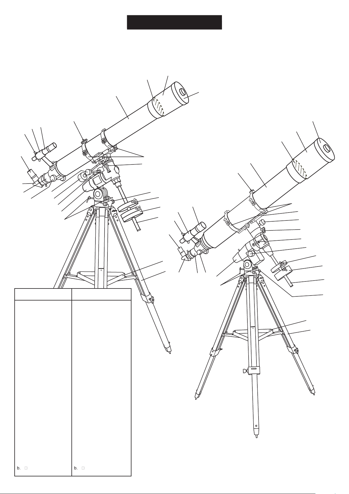
REFRACTOR
B
A
EQ5
A
B
H
G
NEQ3
C
D
E
F
C
I
11
10
D
E
J
K
1
L
2
3
4
5
9
8
7
G
6
H
I
F
12
(150mm/1200mm)
11
10
9
8
7
a
b
J
K
L
1
6
5
4
2
EQ3-2
EQ5
3
Dust Cap/Mask
A.
(Remove before Viewing)
Sun Shade
B.
Objective Lens
C.
Telescope Main Body
D.
Piggyback Bracket
E.
Finderscope
F.
Finderscope Bracket
G.
Alignment Screw
H.
Eyepiece
I.
Diagonal
J.
Focus Tube
K.
Focus Knob
L.
1.
R.A. Flexible Control
Cable
2.
Dec. Flexible Control
Cable
3.
R.A. Lock knob
4.
Polarscope Holder
(not shown)
5.
Altitude Adjustment T-bolts
6.
Counterweight Rod
7.
Counterweight
8.
Counterweight Thumb
Screw
9.
Azimuth Adjustment Knob
10.
Dec. Lock Knob
11.
Tube Rings
a.
Accessory Tray
Tripod Leg
Dust Cap/Mask
A.
(Remove before Viewing)
Sun Shade
B.
Objective Lens
C.
Telescope Main Body
D.
Piggyback Bracket
E.
Finderscope
F.
Finderscope Bracket
G.
Alignment Screw
H.
Eyepiece
I.
Diagonal
J.
Focus Tube
K.
Focus Knob
L.
Polarscope Holder
1.
(not shown)
Altitude Adjustment T-bolts
2.
Azimuth Adjustment Knob
3.
Counterweight Rod
4.
Counterweight
5.
Counerweight Thumb
6.
Screw
R.A. Control Knob
7.
R.A. Lock Knob
8.
Dec. Lock Knob
9.
Dec. Control Knob
10.
Mounting Plate
11.
(150mm/1200mm)
Tube RIngs
12.
a.
Accessory Tray
Tripod Leg
a
b
2
Page 3
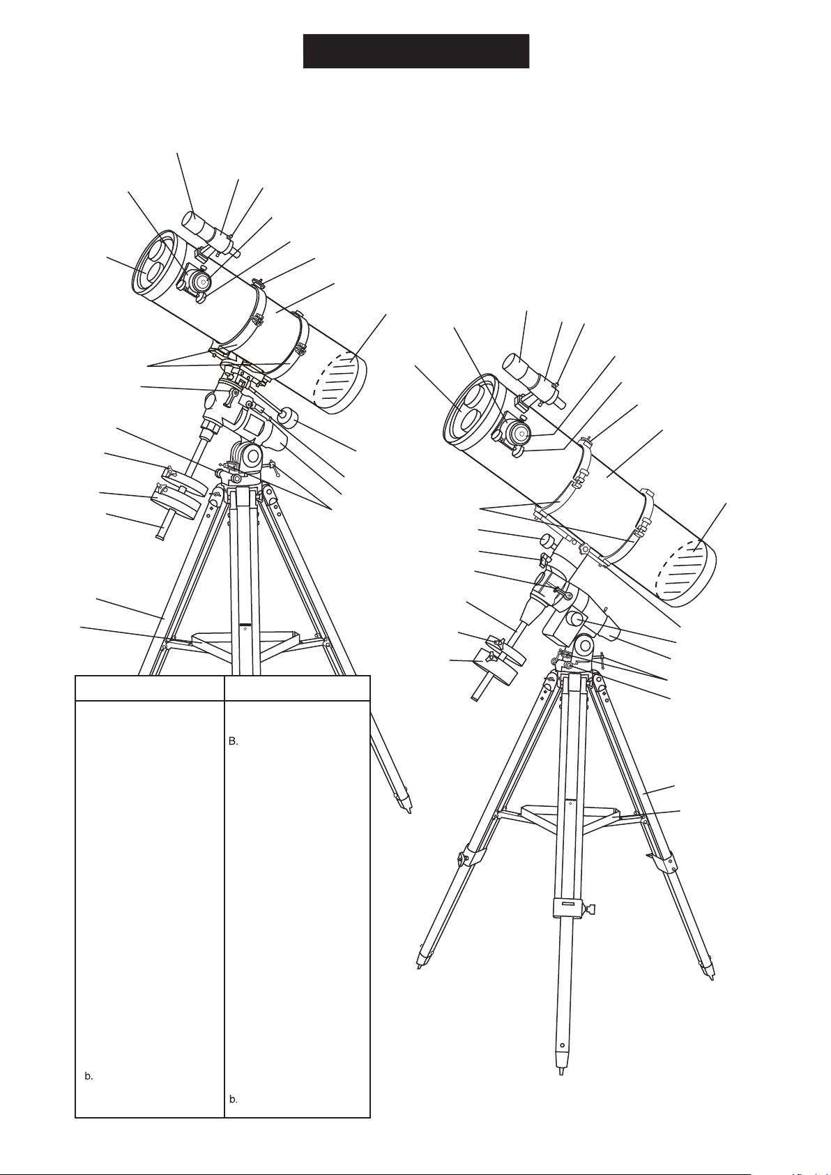
REFLECTOR
C
B
NEQ3
D
E
F
G
A
H
EQ5
I
J
B
10
A
9
8
7
1
C
D
E
F
G
H
I
2
6
5
3
4
12
11
10
9
J
a
b
Dust Cap/Mask
A.
(Remove before Viewing)
Focus Tube
B.
Finderscope
C.
Finderscope Bracket
D.
Finderscope Adjustment
E.
Screws
Eyepiece
F.
Focus Knob
G.
Piggyback Bracket
H.
Telescope Main Body
I.
Primary Mirror Position
J.
1.
Dec. Flexible Control
Cable
2.
R.A. Lock Knob
3.
Polarscope Holder
(not shown)
4.
Altitude Adjustment T-bolts
5.
Counterweight Rod
6.
Counterweight
7.
Counterweight Thumb
Screw
8.
Azimuth Adjustment Knob
9.
Dec. Lock Knob
10.
Tube Rings
a.
Tripod Leg
Accessory Tray
EQ5EQ3-2
Dust Cap/Mask
A.
(Remove before Viewing)
Focus Tube
Finderscope
C.
Finderscope Bracket
D.
Finderscope Adjustment
E.
Screws
Eyepiece
F.
Focus Knob
G.
Piggyback Bracket
H.
Telescope Main Body
I.
Primary Mirror Position
J.
Mounting Plate
1.
(200mm/1000mm)
R.A. Control Knob
2.
Polorscope Holder
3.
(not shown)
Altitude Adjustment T-bolts
4.
Azimuth Adjustment Knob
5.
Counterweight
6.
Counterweight Thumb
7.
Screw
Counterweight Rod
8.
R.A. Lock Knob
9.
Dec. Lock Knob
10.
Dec. Control Knob
11.
Tube Rings
12.
a.
Tripod Leg
Accessory Tray
8
(200mm/1000mm)
7
1
2
6
3
4
5
a
b
3
Page 4
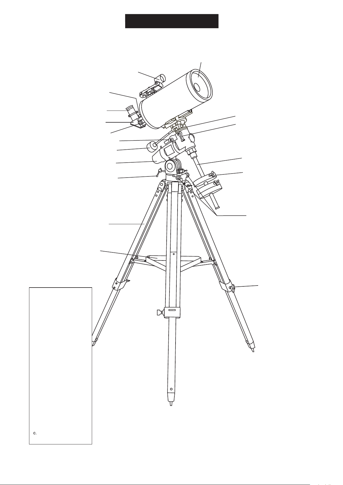
MAKSUTOV
NEQ3
A
B
C
D
E
9
8
F
1
2
7
3
6
4
5
a
Dust Cap (not shown,
A.
remove before Viewing)
Red Dot Finder
B.
Focus Locking Screw
C.
D.
Eyepiece
E.
Diagonal
F.
Focusing Knob
1.
R.A Lock Knob
2.
Dec Flexible Control
Cable
3.
Polarscope Holder/
Polarscope (not shown,
optional)
4.
Altitude Adjustment T-bolt
5.
Azimuth Adjustment
Knobs
6.
Counterweight Locking
Thumb Screw
7.
Counterweight Rod
8.
Dec Lock Knob
9.
Dec Setting Circle
b
c
a.
Tripod Leg
b.
Accessory Tray
Height Adjustment
Clamp
4
Page 5
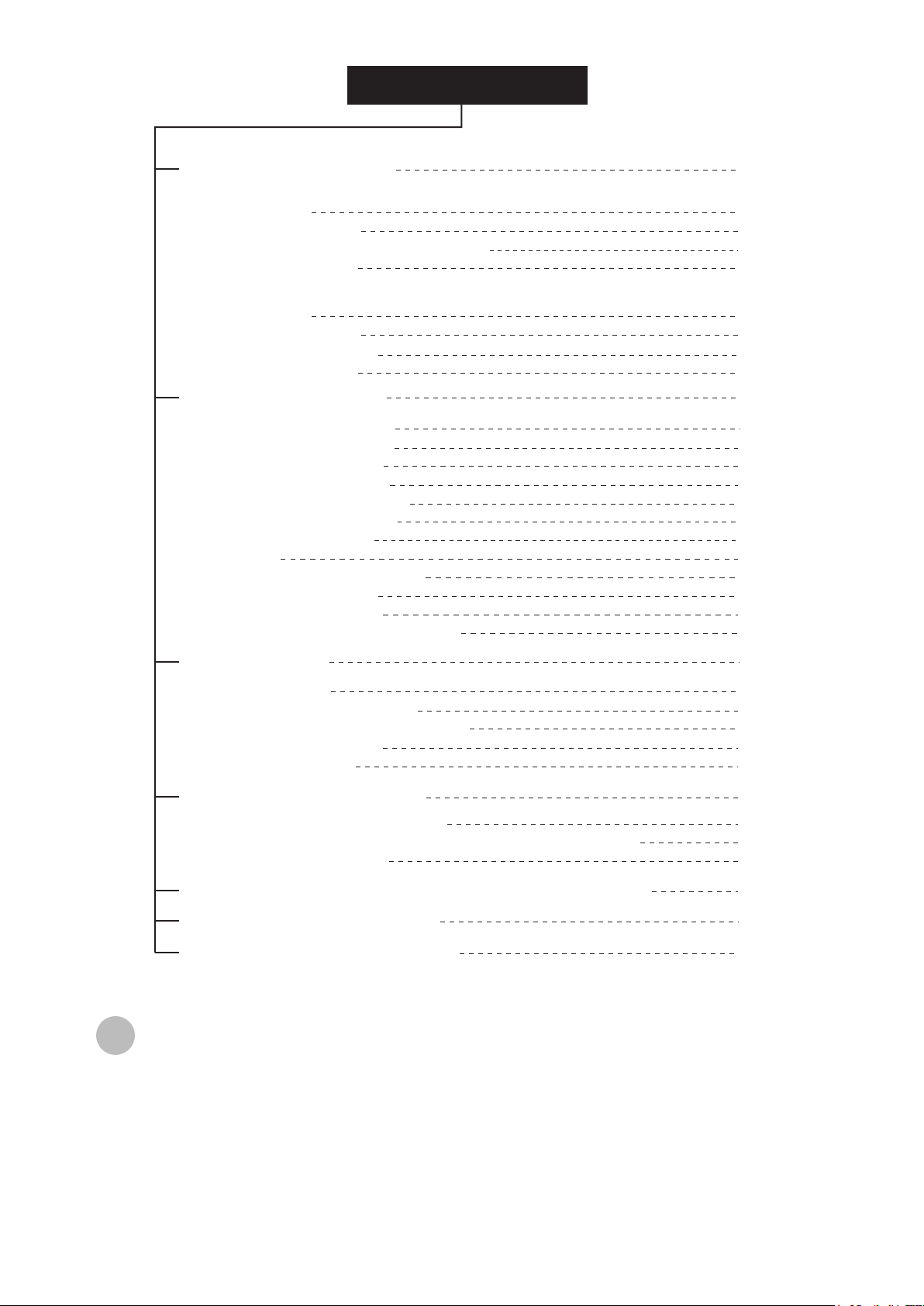
TABLE OF CONTENTS
Assembling Your Telescope
For NEQ3
Tripod Set up
Telescope Assembly
Finderscope/Red Dot Finder Assembly
Eyepiece Assembly
For EQ5
Tripod Set up
Telescope Assembly
Finderscope Assembly
Eyepiece Assembly
Operating Your Telescope
Aligning the Finderscope
Using the Red Dot Finder
Balancing the telescope
Using the leveling bubble
Operating the NEQ3 Mount
Operating the EQ5 Mount
Using the Barlow Lens
Focusing
Polar Alignment for visual use
Pointing your telescope
Using the setting circles
Choosing the appropriate eyepiece
6
6
6
7
7
8
8
9
9
10
10
10
11
11
12
12
13
13
13
14
16
18
Observing the Sky
Sky Conditions
Selecting an Observing Site
Choosing the Best Time to Observe
Chooling the Telescope
Adapting Your Eyes
Proper Care for Your Telescope
Collimating a Newtonian reector
Collimating a refractor (with the adjustable objective-lens cell)
Cleaning Your Telescope
Appendix A-Precise polar alignment for Northern Hemisphere
Appendix B-Optional Accessories
Appendix C-Recommended Reading
efore you begin
B
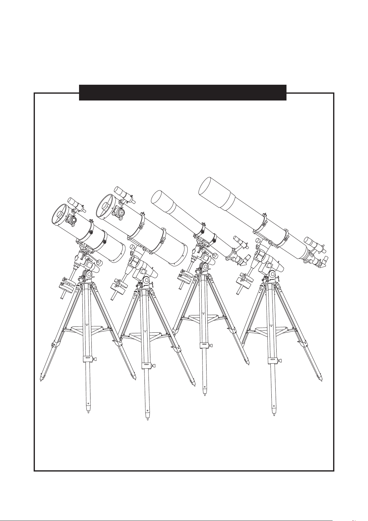
This instruction manual is applicable to all the models with the EQ3-2 or EQ5 mount. Take a moment
to find the model closest to your telescope on p.2 p.3, and p4. Follow the instructions for your specific
model in the manual. Read the entire instructions carefully before beginning. Your telescope should
be assembled during daylight hours. Choose a large, open area to work to allow room for all parts to
be unpacked.
19
19
19
19
19
19
20
20
22
22
I
III
IV
Page 6
FOR NEQ3 MOUNT
TRIPOD SET UP
Fig. 1
ADJUSTING THE TRIPOD LEGS (Fig.18)
1) Slowly loosen the height adjustment clamp and
gently pull out the lower section of each tripod leg.
Tighten the clamps to hold the legs in place.
2) Spread the legs apart to stand the tripod upright.
3) Adjust the height of each tripod leg until the
tripod head is properly leveled. Note that the
tripod legs may not be at same length when
the equatorial mount is level. Do not over tighten
the clamps.
ATTACHING THE ACCESSORY TRAY (Fig.2)
1) Place the accessory tray on top of the bracket, and
secure with the locking thumb screws from underneath.
ATTACHING THE MOUNT TO THE TRIPOD (Fig.3)
1) Align metal dowel on the tripod head with the gap
between the azimuthal adjustment knobs underneath
the mount. Tighten the knurled knob underneath the
tripod head to secure mount to tripod.
Note: Loosen the azimuthal adjustment knobs if mount does not
fit into tripod head completely. Retighten knobs to secure.
Fig. 2
Fig. 3
Fig. 7
TELESCOPE ASSEMBLY
Fig. 4
ATTACHINGTHE MOUNTING
PLATE (Fig.7)
1) Align the screws with the grooves
2) Secure by tightening the two
INSTALLING THE COUNTERWEIGHT(S) (Fig.4, 5)
1) Locate the counterweight rod.
2) Screw the counterweight rod into the threaded hole
on the end of the declination shaft. Tighten the locknut
on counterweight rod until it is locked against the mount.
3) Unscrew the threaded cap from the end of the
counterweight rod.
4) Locate the counterweight(s) and slide them
halfway along the counterweight rod.Tighten
the counterweight thumbscrews to secure.
5) Replace the cap on the end of the
counterweight rod.
INSTALLING THE CONTROL CABLES (Fig.6)
1) Slide the sleeve end of the cable over the
(short mounting plate)
on the side of the mounting bar.
Position the mounting plate
on the mounting bracket.
locking screws.
Fig. 5
nipple on the end of the worm gear. Secure
the cable by tightening the set screw against
the flat surface of the nipple.
(long mounting plate)
Fig. 8
ATTACHING THE
MOUNTING PLATE (Fig.8)
1) Position the mounting plate
on the mounting bracket.
2) Secure by tightening
the two locking screws.
6
Page 7
TELESCOPE ASSEMBLY
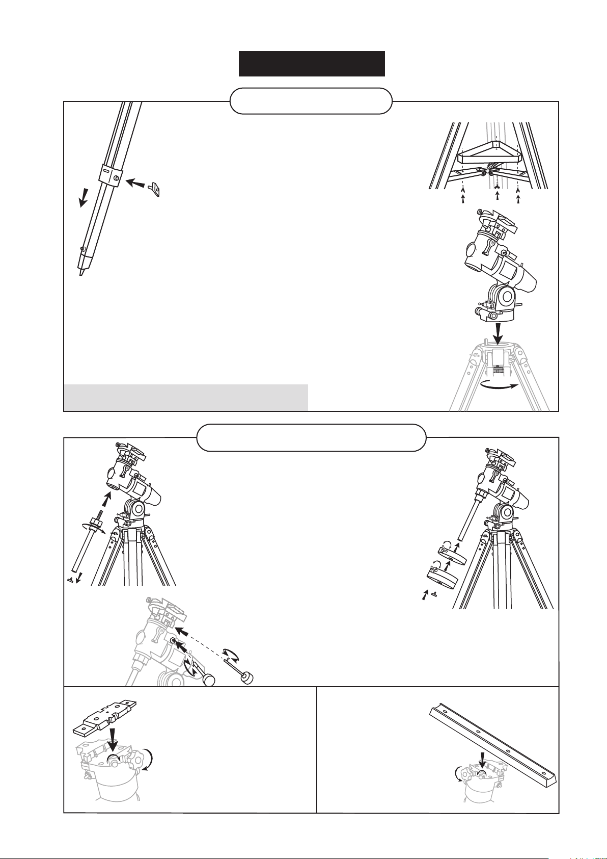
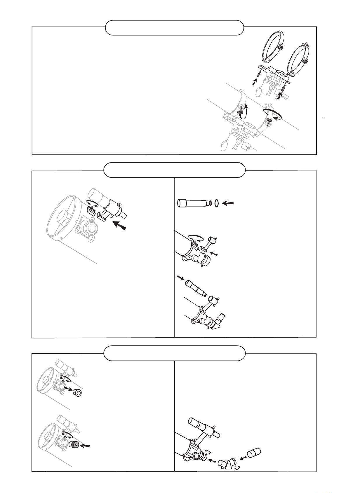
ATTACHING THE TUBE RINGS TO THE MOUNT (Fig.9)
1) Remove the telescope tube assembly from
its plastic packaging.
2) Remove the tube rings from the telescope by
releasing their thumb nuts and opening their hinges.
3) Using the bolts provided, fasten the tube rings to
the mount with the 10mm wrench provided.
ATTACHING THE TELESCOPE MAIN TUBE
TO THE TUBE RINGS (Fig.10)
1) Remove the telescope tube from the paper covering.
2) Find the center of balance of the telescope tube.
Place this in between the two tube rings. Close the
hinges around the telescope and fasten securely by
tightening the thumb nuts. Do not over tighten.
FINDERSCOPE/RED DOT FINDER ASSEMBLY
(reector and Maksutov)
Fig.11
ATTACHING THE FINDERSCOPE
BRACKET/RED DOT FINDER (Fig.11)
1) Locate the nderscope optical assembly
or Red Dot Finder.
2) Slide the nderscope bracket/Red Dot
Finder into the rectangular slot and tighten
the screw to hold the mount in place.
Fig.10
(refractor)
Fig.12
Fig.13
Fig.14
Fig.9
ATTACHING THE FINDERSCOPE (Fig.12, 13, 14)
1) Locate the nderscope bracket.
Carefully remove the rubber-o ring from the nderscope bracket.
2) Position the o-ring into the
groove located approximately
half-way along the nderscope
tube.
3) Locate the nderscope optical
assembly.
4) Slide the nderscope bracket
into the rectangular slot and
tighten the screw to hold the
mount in place.
5) Position the nderscope into
its mount by sliding it backwards
until the rubber o-ring seats
in the nderscope mount.
Fig.15
Fig.16
EYEPIECE ASSEMBLY
(reector)
INSERTING THE EYEPIECE
(Fig.15, 16)
1) Unscrew the thumbscrews
on the end of the focus tube
to remove the black plastic
end-cap.
2) Insert the desired eyepiece
and secure it by retightening
the thumbscrews.
(refractor and
Maksutov)
Fig.17
7
INSERTING THE EYEPIECE
(Fig.17)
1) Loosen the thumbscrew on the
end of the focus tube.
2) Insert the diagonal into the focus
tube and re-tighten the thumbscrew
to hold the diagonal in place.
3) Loosen the thumbscrews
on the diagonal.
4) Insert the desired eyepiece
into diagonal and secure by re tightening the thumbscrews.
Page 8
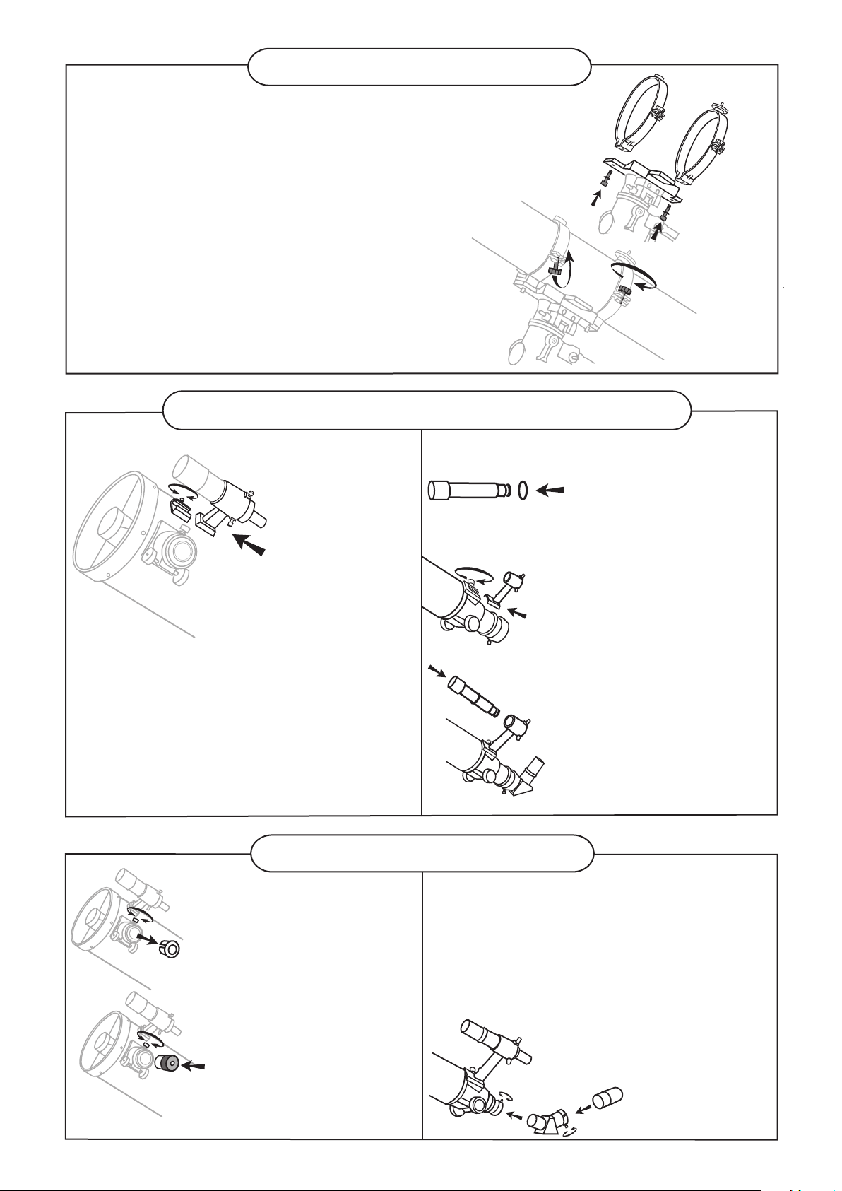
FOR EQ5 MOUNT
TRIPOD SET UP
Fig.18
1) Slowly loosen the height adjustment clamp and
gently pull out the lower section of each tripod leg.
Tighten the clamps to hold the legs in place.
2) Spread the legs apart to stand the tripod upright.
3) Adjust the height of each tripod leg until the
tripod head is properly leveled. Note that the
tripod legs may not be at same length when
the equatorial mount is level. Do not over tighten
the clamps.
ATTACHING THE ACCESSORY TRAY (Fig.19)
ADJUSTING THE TRIPOD LEGS (Fig.18)
1) Place th e accessory tray on top of the bracket, and
secure with the locking thumb screws from underneath.
ATTACHING MOUNT TO TRIPOD (Fig.20)
1) Align metal dowel on the tripod head with the gap
between the azimuthal adjustment knobs underneath
the mount. Tighten the knurled knob underneath the
tripod head to secure mount to tripod.
Note: Loosen the azimuthal adjustment knobs if mount does not
t into tripod head completely. Retighten knobs to secure.
Fig.19
Fig.20
Fig.23
TELESCOPE ASSEMBLY
INSTALLING COUNTERWEIGHT (Fig.21, 22)
Fig.21
ATTACHING THE MOUNTING
PLATE (Fig.23)
1) Position the mounting plate
on the mounting bracket.
2) Secure by tightening the two
locking screws.
Note: The screws should align with the
grooves in the side of the mounting bar.
1) Locate counterweight rod.
2) Screw counterweight rod into threaded hole on the
end of the declination shaft. Tighten locknut on the
counterweight rod until it is locked against the mount.
3) Unscrew the threaded cap from the end of the
counterweight rod.
4) Locate the counterweights and slide them halfway
along the counterweight rod. Tighten the counterweight
thumb screws to secure.
5) Replace the cap on the end of the counterweight rod.
(short mounting plate)
Fig.22
(long mounting plate)
Fig.24
ATTACHING THE
MOUNTING PLATE (Fig.24)
1) Position the mounting plate
on the mounting bracket.
2) Secure by tightening
the two locking screws.
8
Page 9
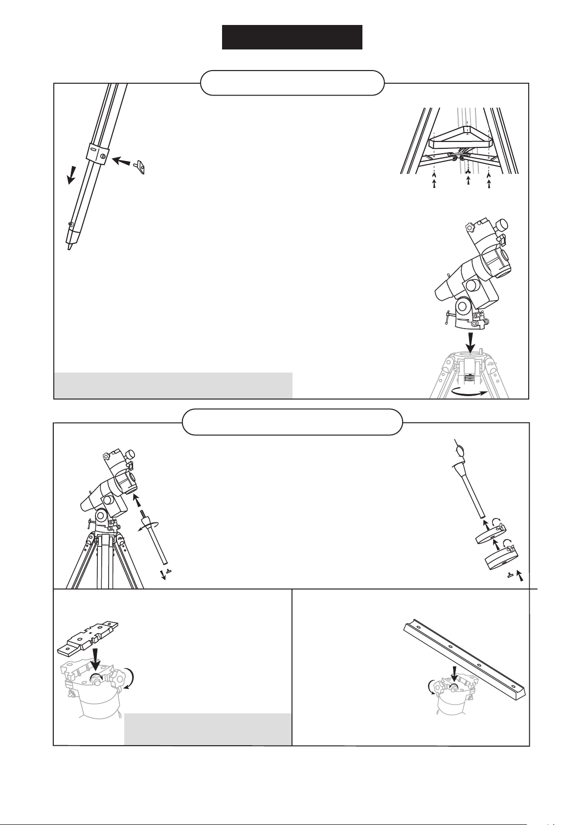
TELESCOPE ASSEMBLY
ATTACHING THE TUBE RINGS TO THE MOUNT(Fig.25)
1) Remove the telescope tube assembly
from its plastic packaging.
2) Remove the tube rings from the telescope by releasing
their thumb nuts and opening their hinges.
3) Using the bolts provided, fasten the tube rings to
the mount with the 10mm wrench provided.
ATTACHING THE TELESCOPE
MAIN TUBE TO THE TUBE RINGS (Fig.26)
1) Remove the telescope tube from the paper covering.
2) Find the center of balance of the telescope tube.
Place this in between the two tube rings. Close the
hinges around the telescope and fasten securely by
tightening the thumb nuts.
FINDERSCOPE ASSEMBLY
(reector)
Fig.27
ATTACHING THE FINDERSCOPE
BRACKET (Fig.27)
1) Locate the nderscope optical assembly.
2) Slide the nderscope bracket into
the rectangular slot and tighten the
screw to hold the mount in place.
Fig.26
(refractor)
Fig.28
Fig.29
Fig.30
Fig.25
ATTACHING THE FINDERSCOPE (Fig.28, 29, 30)
1) Locate the nderscope
bracket. Carefully remove
the rubber-o-ring from the
nderscope bracket.
2) Position the o-ring into the
groove located approximately
half-way along the nderscope
tube.
3) Locate the nderscope optical
assembly.
4) Slide the nderscope bracket
into the rectangular slot and
tighten the screw to hold the
mount in place.
5) Position the nderscope into its
mount by sliding it backwards
until the rubber o-ring seats
in the nderscope mount.
Fig.31
Fig.32
EYEPIECE ASSEMBLY
(reector)
INSERTING THE EYEPIECE
(Fig.31, 32)
1) Unscrew the thumbscrews
on the end of the focus
tube to remove the black
plastic end-cap.
2) Re-tighten thumb screws to
hold the eyepiece in place.
(refractor)
Fig.33
9
INSERTING THE EYEPIECE
(Fig.33)
1) Loosen the thumbscrew on the
end of the focus tube.
2) Insert the diagonal into the focus
tube and re-tighten thumbscrew
to hold the diagonal in place.
3) Loosen the thumbscrews
on the diagonal.
4) Insert the desired eyepiece
into diagonal and secure by
re-tightening the thumbscrews.
Page 10

ligning the nde
A
Fig.a
Fig.a1
OPERATING YOUR TELESCOPE
scope
r
The finderscope (optical or red dot) is a very useful accessory
that is included with your telescope. When the finderscope is
correctly aligned with the telescope, objects can be quickly
located and brought to the centre of the field. Alignment is best
done outdoors in day light when it's easier to locate objects. If
it is necessary to refocus your finderscope, sight on an object
that is at least 500 yards (metres) away. Loosen the locking
ring by unscrewing it back towards the bracket. The front lens
holder can now be turned in and out to focus. When focus is
reached, lock it in position with the locking ring (Fig.a).
1)
Choose a distant object that is at least 500 yards away and
point the main telescope at the object. Adjust the telescope
so that the object is in the centre of the view in your
eyepiece.
2)
Check the finderscope to see if the object centred in the
main telescope view is centred on the crosshairs.
3)
Adjust the two small screws to centre the finderscope
crosshairs on the object (Fig.a1).
scope
sing the Red Dot Finde
U
The Red Dot Finder is a zero magnification pointing
tool that uses a coated glass window to superimpose
the image of a small red dot onto the night sky. The
Red Dot Finder is equipped with a variable brightness
control, azimuth adjustment control, and altitude
adjustment control (Fig.b). The Red Dot Finder is
powered by a 3-volt lithium battery located underneath
at the front. To use the Finder, simply look through the
sight tube and move your telescope until the red dot
merges with the object. Make sure to keep both eyes
open when sighting.
Aligning the Red Dot Finder
Like all finderscopes, the Red Dot Finder must be
properly aligned with the main telescope before use.
This is a simple process using the azimuth and altitude
control knobs.
1)
Open the battery cover by pulling it down (you can
gently pry at the 2 small slots) and remove the
plastic shipping cover over the battery (Fig.b1).
2)
Turn on the Red Dot Finder by rotating the variable
brightness control clockwise until you hear a "click".
Continue rotating the control knob to increase the
brightness level.
3)
Insert a low power eyepiece into the telescope's
focuser. Locate a bright object and position the
telescope so that the object is in the centre of the
field of view.
4)
With both eyes open, look through the sight tube at
the object. If the red dot overlaps the object, your
Red Dot Finder is perfectly aligned. If not, turn its
azimuth and altitude adjustment controls until the
red dot is merged with the object.
r
Fig.b
Altitude
Adjustment
Control
Fig.b1
ON/OFF
Brightness
Control
Azimuth
adjustment
control
Sight Tube
Battery cover
Plastic
shipping
cover
10
Page 11

alancing the telescope
B
A Telescope should be balanced before each observing session. Balancing reduces stress on the telescope
mount and allows precise control of micro-adjustment. A balanced telescope is specially critical when using
the optional clock drive for astrophotography. The telescope should be balanced after all accessories
(eyepiece, camera, etc.) have been attached. Before balancing your telescope, make sure that your tripod is
balanced and on a stable surface. For photography, point the telescope in the direction you will be taking
photos before performing the balancing steps.
R.A. Balancing
1)
For best results, adjust the altitude of
the mount to between 15º and 30º if
possible, by using the altitude
adjustment T-bolt.
2)
Slowly unlock the R.A. and Dec. lock
knobs. Rotate the telescope until
both the optical tube and the
counterweight rod are horizontal to
the ground, and the telescope tube
is to the side of the mount (Fig.c).
3)
Tighten the Dec. lock knob.
4)
Move the counterweight(s) along the
counterweight rod until the
telescope is balanced and remains
stationary when released.
5)
Tighten the counterweight thumb
screws to hold counterweight(s) in
their new position.
Dec. Balancing
All accessories should be attached to the telescope before balancing around the declination axis. The R.A.
balancing should be done before proceeding with Dec. balancing.
1)
For best results, adjust the altitude of the mount to between 60º and 75º if possible.
2)
Release the R.A. lock knob and rotate around the R.A. axis so that the counterweight rod is in a horizontal
position. Tighten the R.A. lock knob.
3)
Unlock the Dec. lock knob and rotate the telescope tube until it is parallel to the ground.
4)
Slowly release the telescope and determine in which direction it rotates. Loosen the telescope tube rings and
slide the telescope tube forward or backward in the rings until it is balanced.
5)
Once the telescope no longer rotates from its parallel starting position, re-tighten the tube rings and the Dec.
lock knob. Reset the altitude axis to your local latitude.
Fig.c
N
sing the le
U
For best telescope performance, the equatorial mount
should be properly leveled. A level tripod allows easier
fine adjustment of controls and better weight distribution.
This equatorial mount includes a small leveling bubble
near its base (Fig.d). Adjust the height of each tripod leg
until the bubble appears in the center of the circle. Note
that the tripod legs may not be at same length when the
equatorial mount is level.
veling
b
11
le
b
ub
Fig.d
Leveling bubble
Page 12

perating the NEQ3 mount
O
The NEQ3 mount has controls for both conventional
altitude (up-down) and azimuth (left-right) directions of
motion. These two adjustments are suggested for large
direction changes and for terrestrial viewing. The two
azimuth adjustment knobs located near the tripod head
allow fine-adjustment of azimuth for polar alignment.
Use the altitude adjustment T-bolts for altitude
adjustments. These allow fine-adjustment for setting the
mount to your local latitude. (Fig.e).
In addition, this mount has Right Ascension (hour
angle) and Declination direction controls for
polar-aligned astronomical observing. Loosen the lock
knobs to make large direction changes. Use the control
cables for fine adjustment after the lock knobs have
both been locked (Fig.e1). An additional scale is
included for the altitude axis. This allows polar
alignment for your local latitude. (Fig.e2)
Fig.e
Azimuth
adjustment
Fig.e1
Dec.
adjustment
Altitude
adjustment
Dec. fine
adjustment
R.A. fine
adjustment
R.A. adjustment
Fig.e2
0
10
20
30
40
50
60
70
80
90
Latitude scale
perating the EQ5 mount
O
The EQ5 mount has controls for both conventional
altitude (up-down) and azimuth (left-right) directions of
motion. These two adjustments are suggested for
large direction changes and for terrestrial viewing. The
two azimuth adjustment knobs located near the tripod
head allow fine-adjustment of azimuth for polar
alignment. Use the altitude adjustment T-bolts for
altitude adjustments. These allow fine-adjustment for
setting the mount to your local latitude. (Fig.f).
In addition, this mount has Right Ascension (hour
angle) and declination direction controls for
polar-aligned astronomical observing. Loosen the lock
knobs to make large direction changes. Use the
control cables for fine adjustment after the lock knobs
have both been locked (Fig.f1). An additional scale is
included for the altitude axis. This allows polar
alignment for your local latitude. (Fig.e2)
Fig.f
Azimuth
adjustment
Fig.f1
Dec. fine
adjustment
Dec. adjustment
Altitude
adjustment
R.A. adjustment
R.A. fine
adjustment
12
Page 13

w lens (optional)
sing the Barl
U
o
A Barlow is a negative lens which increases the
magnifying power of an eyepiece, while reducing the
field of view. It expands the cone of the focussed light
before it reaches the focal point, so that the telescope's
focal length appears longer to the eyepiece.
The Barlow is inserted between the focuser and the
eyepiece in a reflector, and usually between the diagonal
and the eyepiece in a refractor or a maksutov (Fig.g).
With some telescopes, it can also be inserted between
the focuser and the diagonal, and in this position it gives
even greater magnification. For example, a 2X Barlow
when inserted after the diagonal can become 3X when
placed in front of the diagonal.
Fig.g
Barlow
Diagonal
(Refracting Telescopes
and Maksutovs)
Barlow
Eyepiece
Eyepiece
In addition to increasing magnification, the benefits of
using a Barlow lens include improved eye relief, and
reduced spherical aberration in the eyepiece. For this
reason, a Barlow plus a lens often outperforms a single
lens producing the same magnification. However, its
greatest value may be that a Barlow effectively doubles
the number of eyepieces in your collection.
ocusing
F
Slowly turn the focus knobs under the focuser, one way
or the other, until the image in the eyepiece is sharp
(Fig.h). The image usually has to be finely refocused
over time, due to small variations caused by temperature
changes, flexures, etc. This often happens with short
focal ratio telescopes, particularly when they haven't yet
reached outside temperature. Refocusing is almost
always necessary when you change an eyepiece or add
or remove a Barlow lens.
Visual Use
or
olar Alignment
P
f
Tracking of celestial objects can be simplified by
performing a procedure known as a polar alignment. For
visual use the procedure does not require high precision.
For satisfactory results all you need to do is point your
mount at Polaris, the North Star.
To point at Polaris, start by aiming the north leg of the
tripod north. Next, adjust the altitude angle of the mount so
that you can see Polaris through the polar axis view port.
Note that the proper altitude angle is equal to your local
latitude. If you know your local latitude simply adjust the
front and back latitude adjustment bolts until the indicator
points to your local latitude on the scale. Fig. j. To find your
local latitude you can consult a road map, call your airport,
or look it up on the Internet.
(Reflecting Telescopes)
Fig.h
Polaris
Fig.i
Polaris axis
view point
Dec. setting
circle
If you can see Polaris through your polar scope
view port, you are polar aligned sufficiently for
most visual applications.
Fig.j
Front Latitude
adjuster
Azimuth
adjusters
These are the main controls for adjusting the position of
your mount to aim it at Polaris. Here, the latitude is set to
approximately 40 degrees. East/west adjustments are made
with the Azimuth adjusters.Up/down adjustments are made
with the Latitude adjusters.
0
10
20
30
40
50
60
70
80
90
R.A Setting circle
Rear Latitude
adjuster
13
Page 14

Page 15

Fig.m
You aim your telescope by rotating it along the RA and
Dec axes of your mount. In the upper image the
telescope is in the HOME position, aimed due north.
The side images show the telescope pointing NE (right
side) and SW (left side). The bottom image shows the
telescope pointing due south.
After pointing at an object and tracking it for a while you may find the counterweight(s) rise above the point of
being parallel to the ground. If so, it is time to perform a meridian flip. This is necessary to prevent your
telescope from eventually colliding with the mount or tripod.
To do a meridian flip, rotate your telescope 180 degrees in Dec and lock the Dec axis. Now, rotate your mount
12H in RA and lock the RA axis. Using the setting circles to assist you will help you do this more accurately.
When finished you should be pointing at the same object you were pointing at before, but from the opposite side
of your mount. Don’t forget to adjust your RA setting circles back to the coordinates of your object. Lock the
setscrew when done.
15
Page 16

sing the Setting Cir
U
c
les
Now it is time to learn what those numbered dials are for!
The dials are called setting circles and they can be used
Fig.n
0
2
4
6
8
10
to help you find objects in the sky simply by dialing in a
set of coordinates.
All objects in the sky have assigned coordinates labeled
Right Ascension (RA for short) and Declination (Dec for
short). The RA axis follows east/west movement of the
1
2
3
21
4
20
8
23
22
10
9
23
0
22
1
11
21
2
20
3
4
12
sky and is the primary axis. By periodically rotating the RA
axis you are able to follow the apparent motion of the sky
and keep objects centered in your eyepiece. This is called
tracking.
The Dec axis is for north/south positions. It is primarily
used for finding objects, not for tracking them. It is normal,
however, to make occasional adjustments to the Dec axis
as well. The better your polar alignment, the fewer Dec
The RA setting circle is numbered from 1 to 24 in 10
minute increments. The example above shows the mount
is set to the RA coordinates of 8h 20m. The lower scale
marked 1 to 12 is the date scale. The upper scale is the
RA minute scale. Both of these can be ignored when
using the setting circle scale for finding objects.
adjustments you will need to make.
First you need to calibrate the RA axis (Fig.n). To do this align your telescope to an object with known
coordinates and then rotate the RA setting circle to show those coordinates. Leave the setscrew unlocked at this
point. Your Dec scale is factory set and does not need to be calibrated in this way. Once you are aimed at the
known object the Dec scale should have the correct coordinate reading.
Now as you rotate the scope in RA and Dec, the setting circle values change. So, to find a specific object, you
simply turn both the axes until the designated coordinates line up with the pointers on the respective scales.
After finding the object, centre it in your eyepiece, then lock the RA set screw securely. This will prevent the RA
setting from incrementing as the telescope tracks the object. You only want the RA setting circle to rotate with the
mount when you are locating objects, not when tracking them.
Let’s do an example. During summer nights the star Vega shines brightly overhead (Fig.0). Vega is easy to find
because it is so much brighter than any other stars in its general vicinity. It’s easiest to find Vega by spotting the
Summer Triangle. This is a trio of bright stars in the eastern sky consisting of Deneb (Cygnus), Altair (Aquila) and
Vega (Lyra). Vega is the westernmost of the three stars. It will be highest overhead of the three for northern
observers. Find Vega and centre it in your eyepiece.
Fig.o
Deneb
Vega
Vega is the brightest star in the
Summer Triangle, which consists of
Deneb (Cygnus), Altair(Aquila) and
Vega (Lyra). In this image Vega is at
the top. In the sky when facing east
it will be the highest of the three
stars with Deneb to its left (north)
and Altair to its lower right (south).
Altair
NE
E
SE
16
Page 17

Vega has the coordinates RA 18h 37m. With Vega centered in your eyepiece loosen the RA setting circle
setscrew and rotate the scale until it reads 18h 36m. (If you are in the Northern hemisphere use the top row of
numbers. If you are in the Southern hemisphere use the lower set of numbers.)
To do this turn the RA dial until 18 is lined up with the indicator. The small divisions are set at 10 minutes each,
so rotate another 3 divisions past 18h in the direction of 19h. This puts you at 18h 30m. Since you are aiming for
18:36, rotate about half of one more division. That will put you approximately at 18:35, and that is close enough
for visual purposes.
Now look at the Dec scale. It should be pointing at 39 degrees, which is the Declination of Vega. If it is not,
loosen the Allen screw on the Dec scale and rotate the scale until it reads 39 degrees. Retighten the Allen screw
when you are done. This will be the only time you will ever need to adjust the Dec scale.
Your mount is now calibrated on Vega and ready to point at other objects using the setting circles. Let’s try it out.
The interesting Ring Nebula (M57) is nearby at: RA 18h 52m and Dec 33 degrees. Unlock the RA scale set
screw, then unlock the RA axis and rotate the mount until the scale reads 18h 52m. Lock the RA axis but don’t
tighten the RA setscrew just yet. Now unlock the Dec axis and rotate the telescope until the Dec axis pointer is
at 33 on the scale. Lock your Dec axis.
When you look through a low power eyepiece you should be able to detect the Ring Nebula in the field of view.
Use your slow motion controls to centre it, then lock the RA setscrew by tightening it fully. When you are ready to
move on to the next object, unlock the RA set screw, then rotate the RA and Dec axes until you arrive at the
desired coordinates.
Meridian Flips
The meridian is an imaginary line that runs
directly overhead from north to south and
divides the sky into east and west (Fig.p).
You will find that any moves of the telescope
that cause you to cross the meridian will
invalidate your setting circles. If you switch
from pointing in the eastern sky to an object
in the western sky (or visa versa) you will
need to perform a meridian flip and manually
reset your RA setting circle.
The procedure for doing a meridian flip is
described in the section on pointing your
Fig.p
Right
Ascension
Equatorial Mount
(Northern Hemisphere)
Object you
are viewing
Declination
Zenith
Mount aligned on
North Celestial Pole
Polaris
telescope. If you do a meridian flip and end
up pointing at the same object you had
been viewing before, don’t forget to reset
the RA setting circle to that object’s
coordinates. If you do a meridian flip and
Meridian
Line
W
Latitude
N
point at a new object, be sure to put its
coordinates on the RA setting circle. As
always, lock down the RA set screw when
switching from finding
objects to tracking them.
S
E
It is a good idea to plan your observing so
that multiple objects in the west are viewed
in sequence before viewing objects in the
east. When viewing multiple objects on the
same side of the sky you do not need to
reset your RA setting circle as often. Why
start in the west? We recommend this
simply because objects in the western sky
will set earlier than objects in the eastern
sky. If you leave them to last, they may set
before you find them!
Plane of local horizon
17
Nadir
Apparent
movement
of stars
Plane of Celestial
Equator
Page 18

epiece
y
opriate
hoosing the app
C
Calculating the magnification (power)
The magnification produced by a telescope is determined by the focal length of the eyepiece that is used with
it. To determine a magnification for your telescope, divide its focal length by the focal length of the eyepieces
you are going to use. For example, a 10mm focal length eyepiece will give 80X magnification with an 800mm
focal length telescope.
r
e
Focal length of the telescope
magnification =
When you are looking at astronomical objects, you are looking through a column of air that reaches to the
edge of space and that column seldom stays still. Similarly, when viewing over land you are often looking
through heat waves radiating from the ground, house, buildings, etc. Your telescope may be able to give very
high magnification but what you end up magnifying is all the turbulence between the telescope and the
subject. A good rule of thumb is that the usable magnification of a telescope is about 2X per mm of aperture
under good conditions.
Calculating the field of view
The size of the view that you see through your telescope is called the true (or actual) field of view and it is
determined by the design of the eyepiece. Every eyepiece has a value, called the apparent field of view, which
is supplied by the manufacturer. Field of view is usually measured in degrees and/or arc-minutes (there are 60
arc-minutes in a degree). The true field of view produced by your telescope is calculated by dividing the
eyepiece's apparent field of view by the magnification that you previously calculated for the combination.
Using the figures in the previous magnification example, if your 10mm eyepiece has an apparent field of view
of 52 degrees, then the true field of view is 0.65 degrees or 39 arc-minutes.
True Field of View =
To put this in perspective, the moon is about 0.5° or 30 arc-minutes in diameter, so this combination would be
fine for viewing the whole moon with a little room to spare. Remember, too much magnification and too small
a field of view can make it very hard to find things. It is usually best to start at a lower magnification with its
wider field and then increase the magnification when you have found what you are looking for. First find the
moon then look at the shadows in the craters!
Focal length of the eyepiece
Apparent Field of View
=
Magnification
800mm
=
= 80X
0.65°
=
10mm
52°
80X
Calculating the exit pupil
The Exit Pupil is the diameter (in mm) of the narrowest point of the cone of light leaving your telescope.
Knowing this value for a telescope-eyepiece combination tells you whether your eye is receiving all of the light
that your primary lens or mirror is providing. The average person has a fully dilated pupil diameter of about
7mm. This value, varies a bit from person to person, is less until your eyes become fully dark adapted and
decreases as you get older. To determine an exit pupil, you divide the diameter of the primary of your
telescope (in mm) by the magnification.
Diameter of Primary mirror in mm
Exit Pupil =
For example, a 200mm f/5 telescope with a 40mm eyepiece produces a magnification of 25x and an exit pupil
of 8mm. This combination can probably be used by a young person but would not be of much value to a
senior. The same telescope used with a 32mm eyepiece gives a magnification of about 31x and an exit pupil
of 6.4mm which should be fine for most dark adapted eyes. In contrast, a 200mm f/10 telescope with the
40mm eyepiece gives a magnification of 50x and an exit pupil of 4mm, which is fine for everyone.
Magnification
18
Page 19

OBSERVING THE SKY
ky conditions
S
Sky conditions are usually defined by two atmospheric characteristics, seeing, or the steadiness of the air,
and transparency, light scattering due to the amount of water vapour and particulate material in the air. When
you observe the Moon and the planets, and they appear as though water is running over them, you probably
have bad "seeing" because you are observing through turbulent air. In conditions of good "seeing", the stars
appear steady, without twinkling, when you look at them with unassisted eyes (without a telescope). Ideal
"transparency" is when the sky is inky black and the air is unpolluted.
electing an obse
S
Travel to the best site that is reasonably accessible. It should be away from city lights, and upwind from any
source of air pollution. Always choose as high an elevation as possible; this will get you above some of the
lights and pollution and will ensure that you aren't in any ground fog. Sometimes low fog banks help to block
light pollution if you get above them. Try to have a dark, unobstructed view of the horizon, especially the
southern horizon if you are in the Northern Hemisphere and vice versa. However, remember that the darkest
sky is usually at the "Zenith", directly above your head. It is the shortest path through the atmosphere. Do not
try to observe any object when the light path passes near any protrusion on the ground. Even extremely light
winds can cause major air turbulence as they flow over the top of a building or wall.
Observing through a window is not recommended because the window glass will distort images considerably.
And an open window can be even worse, because warmer indoor air will escape out the window, causing
turbulence which also affects images. Astronomy is an outdoor activity.
hoosing the best time to obse
C
The best conditions will have still air, and obviously, a clear view of the sky. It is not necessary that the sky be
cloud-free. Often broken cloud conditions provide excellent seeing. Do not view immediately after sunset. After
the sun goes down, the Earth is still cooling, causing air turbulence. As the night goes on, not only will seeing
improve, but air pollution and ground lights will often diminish. Some of the best observing time is often in the
early morning hours. Objects are best observed as they cross the meridian, which is an imaginary line that runs
through the Zenith, due North-South. This is the point at which objects reach their highest points in the sky.
Observing at this time reduces bad atmospheric effects. When observing near the horizon, you look through
lots of atmosphere, complete with turbulence, dust particles and increased light pollution.
rving site
rve
ooling the telescope
C
Telescopes require time to cool down to outside air temperature. This may take longer if there is a big
difference between the temperature of the telescope and the outside air. This minimizes heat wave distortion
inside telescope tube (tube currents). A rule of thumb is to allow 5 minutes per inch of aperture. For example,
a 4 inch refractor would require at least 20 minutes, but an 8" reflector would require at least 40 minutes to
cool off to outside conditions. Tip: use this time for polar alignment.
yes
e
our
dapting
A
Do not expose your eyes to anything except red light for 30 minutes prior to observing. This allows your
pupils to expand to their maximum diameter and build up the levels of optical pigments, which are rapidly lost
if exposed to bright light. It is important to observe with both eyes open. This avoids fatigue at the eyepiece. If
you find this too distracting, cover the non-used eye with your hand or an eye patch. Use averted vision on
faint objects: The center of your eye is the least sensitive to low light levels. When viewing a faint object, don't
look directly at it. Instead, look slightly to the side, and the object will appear brighter.
y
19
Page 20

PROPER CARE FOR YOUR TELESCOPE
ollimating a Newtonian reflector
C
Collimation is the process of aligning the mirrors of your
telescope so that they work in concert with each other to
deliver properly focused light to your eyepiece. By
observing out-of-focus star images, you can test
whether your telescope's optics are aligned. Place a star
in the centre of the field of view and move the focuser so
that the image is slightly out of focus. If the seeing
conditions are good, you will see a central circle of light
(the Airy disc) surrounded by a number of diffraction
rings. If the rings are symmetrical about the Airy disc, the
telescope's optics are correctly collimated (Fig.q).
If you do not have a collimating tool, we suggest
that you make a "collimating cap" out of a plastic
35mm film canister (black with gray lid). Drill or
punch a small pinhole in the exact center of the lid
and cut off the bottom of the canister. This device
will keep your eye centered of the focuser tube.
Insert the collimating cap into the focuser in place
of a regular eyepiece.
Fig.q
Fig.q-1
Fig.q-2
Correctly aligned Needs collimation
Focuser
Support for
secondary mirror
Primary mirror
Secondary mirror
Primary
mirror
Collimation is a painless process and works like this:
Pull off the lens cap which covers the front of the
telescope and look down the optical tube. At the bottom
you will see the primary mirror held in place by three
clips 120º apart, and at the top the small oval
secondary mirror held in a support and tilted 45º toward
the focuser outside the tube wall (Fig.q-1).
The secondary mirror is aligned by adjusting the three
smaller screws surrounding the central bolt. The
primary mirror is adjusted by the three adjusting screws
at the back of your scope. The three locking screws
beside them serve to hold the mirror in place after
collimation. (Fig.q-2)
Aligning the Secondary Mirror
Point the telescope at a lit wall and insert the
collimating cap into the focuser in place of a regular
eyepiece. Look into the focuser through your collimating
cap. You may have to twist the focus knob a few turns
until the reflected image of the focuser is out of your
view. Note: keep your eye against the back of the focus
tube if collimating without a collimating cap. Ignore the
reflected image of the collimating cap or your eye for
now, instead look for the three clips holding the primary
mirror in place. If you can't see them (Fig.q-3), it means
that you will have to adjust the three bolts on the top of
the secondary mirror holder, with possibly an Allen
wrench or Phillip's screwdriver. You will have to
Locking screw
Fig.q-3
Primary mirror clip
Fig.q-4
Primary mirror clip
Mirror cell
Adjusting screw
Ignore the reflected
image for now
Primary mirror clip
Primary mirror clip
20
Page 21

alternately loosen one and then compensate for the slack by tightening the other two. Stop when you see
all three mirror clips (Fig.q-4). Make sure that all three small alignment screws are tightened to secure the
secondary mirror in place.
Aligning the Primary Mirror
Find the three locking screws at the back of your telescope and loosen them by a few turns.
Locking
screw
If you see 3 flat
headed screws and 3
thumbscrews, the flat
Adjusting
screw
headed screws are
the adjusting screws
and the thumbscrews
are the locking
screws.
hex bolt
(Locking screw)
Adjusting screw
If you see 3 hex bolts and 3 Phillip's head screws, the
hex bolts are the locking screws and the Phillip's-head
screws are the adjusting screws. You will need an Allen
wrench to adjust the locking screws.
Now run your hand around the front of your
telescope keeping your eye to the focuser,
you will see the reflected image of your hand.
The idea here is to see which way the primary
mirror is defected; you do this by stopping at
the point where the reflected image of the
secondary mirror is closest to the primary
mirrors' edge (Fig.q-5).
Adjusting screw
Fig.q-5
Secondary
mirror
Locking screw
If you see 3 large nuts
protruding from the back of your
telescope and 3 small
Phillip's-head screws besides
them, the Phillip's-head screws
are the locking screws and the
large nuts are the adjusting
screws.
When you get to that point, stop and keep
your hand there while looking at the back end
of your telescope, is there an adjusting screw
there? If there is you will want to loosen it
(turn the screw to the left) to bring the mirror
away from that point. If there isn't an adjusting
screw there, then go across to the other side
and tighten the adjusting screw on the other
side. This will gradually bring the mirror into
line until it looks like Fig.q-6. (It helps to have
a friend to help for primary mirror collimation.
Have your partner adjust the adjusting screws
according to your directions while you look in
the focuser.)
After dark go out and point your telescope at
Polaris, the North Star. With an eyepiece in
the focuser, take the image out of focus. You
will see the same image only now, it will be
illuminated by starlight. If necessary, repeat
the collimating process only keep the star
centered while tweaking the mirror.
Primary mirror
Fig.q-6
Both mirrors aligned
with collimating cap in
stop and keep your
hand here
Both mirrors aligned with
eye looking in focuser
21
Page 22

ollimating a refractor with the adjustable objective-lens cell
C
Collimation is the process of aligning the lenses of your
telescope so that the light they collect will focus at the right spot
at the back of your telescope for your eyepieces to work.
Collimation is a simple process and works like this:
Pull off the dew cap at the front of your telescope and look into
the scope. The pair of lenses are held in a cell by a threaded
ring. This cell is held in place by three pairs of screws spaced
120 degrees apart. The larger Phillip's head screws actually
hold the cell on, while the smaller, buried Allen screws push
against a ledge at the front of the tube and allow the cell to tilt
slightly, by tension against the Phillips screws (Fig.r). The idea
is to alternately loosen and tighten each against the other until
you have a round star image.
There are a number of devices available for collimation. One of
the best is your eyepiece and Polaris. For this purpose it is best
that your telescope not be polar aligned, in fact point the mount
head due east or west.
Use your lowest power (largest number) eyepiece to acquire
Polaris, place it in the center of the eypepiece view. Now switch
to your next higher power eyepiece, while keeping the image
centered. The in-focus star image will have a bright innermost
point, a slightly fainter inner ring and a fainter still outer ring that
is hard to see (Fig.r-1). If it doesn't look like this, or you can't
reach focus then start with: take out your star diagonal and look
at the image slightly out of focus, this will allow you to gauge
the deflection. A typical off-collimation image will have a bright
spot off to one side when you bring the focus out (Fig.r-2).
The actual process is to slightly loosen the pair on the side the
deflection is, slacken the Allen head screws then tighten the
Phillip's head screws against them again. Check the star image
again after moving it into the centre of the eyepiece. If you find
your image getting worse, then go the other way, or slacken the
other two Allen screws a little. Once you have a round star
image you are set.
Fig.r
Fig.r-1
Correctly aligned
Fig.r-2
It helps to have a friend to help with the collimation.
Needs collimation
Have your partner adjust the screws according to your
directions while you look in the eyepiece.
leaning your telescope
C
Replace the dust cap over the end of the telescope whenever it is not in use. This prevents dust from
settling on the mirror or lens surfaces. Do not clean the mirror or lens unless you are familiar with optical
surfaces. Clean the finderscope and eyepieces with special lens paper only. Eyepieces should be
handled with care, avoid touching optical surfaces.
22
Page 23

APPENDIX A - PRECISE POLAR ALIGNMENT
FOR NORTHERN HEMISPHERE
When your equatorial mount is polar-aligned it is able track the sky easily and hold targets in the eyepiece with
just occasional adjustments to the RA control cable. If your mount is motorized it can hold objects in the
eyepiece almost indefinitely. An accurate polar alignment also greatly reduces the number of guiding
corrections that are needed during long exposure astrophotography.
However, for all but the most critical photographic applications, your polar alignment does not need to be
perfect. Your mount will provide excellent performance even if there is some error in the polar alignment.
SkyWatcher has developed user-friendly equipment and procedures to minimize such errors, and this
makes an adequate polar alignment easy to accomplish.
PREPARING THE MOUNT
Aligning the polar scope reticule
The polar scope needs to be aligned with the polar axis of your mount. The steps below tell you how to perform
this alignment. Note, you can do this procedure at night while pointing at Polaris. However, it is probably easier
to do it in the daytime using a distant point as your target (e.g, a street light a couple of hundred yards away). If
doing the procedure during the day, you might find it convenient to set your altitude to near parallel with the
ground to put the eyepiece of the polar scope into a comfortable position. Just be sure to leave room to make
vertical adjustments in both directions. Also, do this procedure without a telescope or counterweights attached. It
will make turning the mount a lot simpler.
1.
Locate a distant object and place it under the cross at the
centre of the polarscope reticule.
Fig.s-1
If target drifted to here
2
Rotate the mount in RA 180 degrees (i.e., 12 hours on the RA
setting circle).
3.
Note the displacement of your target from the centre of the
crosshairs (Fig.s-1). If it is not displaced at all, it means your
polar scope reticule is already properly aligned and you don't
need to do any more. If it is displaced, continue with the next
step of the alignment procedure.
4.
Use the three adjustment screws on the polar scope to move
the reticule so that exactly one-half of the displacement is
corrected for. For example, if the displacement were about
half an inch in the direction of 1 o'clock, then you would adjust
the cross at the centre of the reticule to go half the distance in
that direction (Figure s-2).
5.
Now continue to move the cross using the altitude and
azimuth adjusters on the mount. When the target is back
under the cross, go back to step 2, but this time rotate the
mount 180 degrees in the opposite direction. If you still get
displacement of the target, repeat steps 3-5.
Setting your latitude
One bolt should always be loose when doing adjustments.
Gently tighten both bolts when your adjustment is complete.
adjust reticule to
place it here (half
the distance)
Fig.s-2
Remove the caps from the upper and lower ends of the RA axis so you can look into the polar scope. Adjust the
north and south T-bolts on the mount so the latitude indicator points to your local latitude (Fig.2). Look through
the polar scope and adjust the azimuth and altitude controls as needed so that Polaris appears in the view of the
polar scope. Once you see it you can use one of the simplified procedures below to place Polaris at the correct
position for an accurate polar alignment.
I
Page 24

SIMPLIFIED POLAR ALIGNMENT PROCEDURES
The NEQ3 and EQ5 mounts have specially designed reticule patterns and simplified procedures to make polar
aligning your mount very simple. In fact, if you purchased a SynScan equipped mount you can perform an
extremely accurate polar alignment in less than two minutes! See the SynScan User manual for details.
If you do not have a SynScan mount you can still get a very good alignment without much bother. The two
simple procedures detailed below work equally well. Use whichever one you like best.
Pattern-based method
Northern Hemisphere - Identify the Big Dipper pattern in the constellation Ursa Major, or find the constellation
Cassiopeia in the night sky. In spring and summer, the Big Dipper will be higher in the sky and easier to find. In
fall and winter, Cassiopeia may be easier to use.
The patterns for both are etched on your polar scope reticule
(Fig.S-3). Simply rotate your mount in RA until one of the
patterns matches its actual orientation in the sky. Lock the RA
axis. Now the small circle on the perimeter of the larger circle
is in the correct position for locating Polaris.
Next, use your azimuth and altitude adjustment controls to
place Polaris inside the small circle. Tighten your azimuth and
altitude knobs, then tighten your locking shaft bolt to secure
the mount to the tripod and you are done.
Pattern-based method
Kochab is the brightest star in the bucket portion of the Little
Dipper (Fig.S-4). It also happens to form a line with Polaris and
the North Celestial Pole (NCP) - the point in space at which you
want to aim your polar axis to achieve an accurate polar
alignment. Kochab rotates around the NCP the way the hour
hand rotates around a clock face, but it takes Kochab nearly 24
hours to make one revolution. We can use this behavior to help
us achieve an accurate polar alignment quickly and simply.
First, identify the bright star Kochab in the bucket of the Little
Dipper. Now look at Polaris and imagine it is the center of a
clock face. Take note of what “time” Kochab appears. For
example, if Kochab were directly to the right of Polaris, it
would be at 3 o’clock. In the figure above, it is at about 8:00.
Fig.s-3
B
i
g
D
i
p
p
e
r
Fig.s-4
10
Polaris
11
Octans
NCP
12
a
i
e
p
o
i
s
s
a
C
1
2
Now look into your polar scope. Rotate your mount in RA to
place the Polaris indicator circle at the time indicated by
Kochab clock method. Then, use your altitude and azimuth
adjustment controls to put Polaris inside the circle. Tighten
your controls and your locking shaft bolt and you are done.
Southern Hemisphere
There is a 4-star pattern in the polar scope, which resembles
the bucket of the Big Dipper. In the Southern Hemisphere,
there is an Asterism in Octans, which has this shape. By
rotating the R.A. axis and by adjusting the altitude and
azimuth of the mount, the four stars in the Asterism can be
placed in the circles in the Pole Finder. This procedure can be
somewhat difficult in the city because all four of these stars
are fainter than Magnitude 5.
II
Polaris
9
Kochab
8
7
6
Kochab is the brightest star in the bucket of
the Little Dipper. Other stars in the region
are quite dim and are not drawn here.
3
4
5
Page 25

APPENDIX B - OPTIONAL ACCESSORIES
NEQ3 & EQ5 SYNSCAN
Sky-Watcher offers simple solutions for users who would like
to attach their smaller telescope to a convenient computerized system but do not wish to deal with the weight of the
HEQ5 or EQ6 mount. The NEQ3 and EQ5 SynScan mounts
use the same Go-To system found in the HEQ5 and EQ6 Pro
mounts. It allows you to point the telescope at a specific
object or even tour the skies at the touch of a button.
DUAL AXIS MOTOR DRIVES
The EQ3 dual axis motor drives precisely control the
telescopes’ tracking speed to compensate for the earth's
rotation. Available in 2x, 4x, and 8x speeds through the Hand
Controller. These DC motor drives run on 4 "D" cell batteries
(not included). Motors for both axes, clutches, cables, hand
controller, and battery case are included.
SINGLE AXIS MOTOR DRIVE
These single axis (R.A.) DC motor drives are powered by 4
"D" cell batteries (not included). A set of batteries will allow
several nights of observing. 2x and 8x tracking speeds (2x
and 4x for EQ1 model) are available through the hand controller. Motor, hand controller, and battery case are included.
COLLIMATING EYEPIECE
The Sky-Watcher Collimation Eyepiece is ideal for precise
collimation of Newtonians and refractors with an adjustable
lenscells. This special eyepiece fits into 1¼" focusers or
diagonals. Alignment is easy using the small opening on one
end and thin crosshairs at the other end.
WIDE-ANGLE EYEPIECES
These Sky-Watcher Wide Angle Eyepieces offer a generous
66° apparent field of view, allowing more sky to be viewed at
one time. They provide sharp image right across the field.
The rubber eyecups are included for viewing comfort and to
keep out extraneous light.
Focal Lengths: 20mm, 15mm, 9mm, 6mm
Eyepiece Barrels: 1.25"
Eye-relief: 14.8mm (W6), 15mm (W9), 13mm (W15), 18mm
(W20)
DUAL FLASHLIGHT
These multipurpose flashlights provide instant switch between
the night vision protecting red light and regular white light. A
convenient control wheel is available for brightness adjustment.
III
Page 26

mateur
A
APPENDIX C - RECOMMENDED READING
Astronomy
stro-photography
A
Beginner's Guide to Amateur Astronomy: An
Owner's Manual for the Night Sky by David J.
Eicher and, Michael Emmerich (Kalmbach
Publishing Co., Books Division, Waukesha,
WI, 1993).
NightWatch: A Practical Guide to Viewing the
Universe by Terence Dickinson, (Firefly Books,
Willowdale, ON, Canada, 3rd edition, 1999).
Star Testing Astronomical Telescopes by
Harold Richard Suiter, (Willmann-Bell, Inc.,
Richmond, VA, 1994).
Star Ware: The Amateur Astronomer's Ultimate
Guide to Choosing, Buying, and Using
Telescopes and Accessories by Philip S.
Harrington (John Wiley & Sons, New York,
1998).
The Backyard Astronomer's Guide by Terence
Dickinson and Alan Dyer (Firefly Books Ltd.,
Willowdale, ON, Canada, revised edition,
1994).
The Great Atlas of the Stars by Serge Brunier,
Constellation photography by Akira Fujii (Firefly
Books; Willowdale, ON, Canada 2001).
A Manual Of Advanced Celestial Photography
by Brad D. Wallis and Robert W. Provin
(Cambridge University Press; New York; 1984).
Astrophotography An Introduction by H.J.P.
Arnold (Sky Publishing Corp., Cambridge,
MA,Sky & Telescope Observer's Guides Series,
ed. Leif J. Robinson, 1995).
Astrophotography for the Amateur by Michael
Covington (Cambridge University Press,
Cambridge, UK, 2nd edition,1999).
Splendors of the Universe: A Practical Guide to
Photographing the Night Sky by Terence
Dickinson and Jack Newton (Firefly Books,
Willowdale, ON, Canada, 1997).
Wide-Field Astrophotography by Robert Reeves
(Willmann-Bell, Inc., Richmond, VA, 2000).
The Beginner's Observing Guide: An
Introduction to the Night Sky for the Novice
Stargazer by Leo Enright, (The Royal
Astronomical Society of Canada, Toronto, ON,
Canada, 1999).
The Deep Sky: An Introduction by Philip S.
Harrington (Sky Publishing Corporation,
Cambridge, MA, Sky & Telescope Observer's
Guides Series, ed. Leif J. Robinson, 1997).
The Universe from Your Backyard: A Guide to
Deep Sky Objects by David J. Eicher
(Kalmbach Publishing Co., Books Division,
Waukesha, WI, 1988).
Turn Left at Orion: A Hundred Night Sky
Objects to See in a Small Telescope--and how
to Find Them by Guy J. Consolmagno and
Dan M. Davis, (Cambridge University Press,
New York, 3rd edition, 2000)
bservational References
O
A Field Guide to the Stars and Planets by Jay
M. Pasachoff, (Houghton Mifflin Company,
1999).
Atlas of the Moon by Antonín Rükl (Kalmbach
Publishing Co., Books Division, Waukesha,
WI, 1993).
Burnham's Celestial Handbook: An Observer's
Guide to the Universe Beyond the Solar
System by Robert Burnham (Dover
Publications, New York; 3- volume set, 1978).
Observer's Handbook by The Royal
Astronomical Society of Canada, (University of
Toronto Press, Toronto, ON, Canada,
published annually).
Sky Atlas 2000.0 by Wil Tirion and Roger W.
Sinnott (Sky Publishing Corp., Cambridge, MA,
2nd edition, 1998).
IV
Page 27

 Loading...